
You also want an ePaper? Increase the reach of your titles
YUMPU automatically turns print PDFs into web optimized ePapers that Google loves.
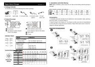
Step 3: UPS output connection<br />
• For socket-type outputs, there two kinds of outputs: programmable outlets and general<br />
outlets. Please connect non-critical devices to the programmable outlets and critical<br />
devices to the general outlets. During power failure, you may extend the backup time to<br />
critical devices by setting shorter backup time for non-critical devices.<br />
• For terminal-type input or outputs, please follow below steps for the wiring configuration:<br />
a) Remove the small cover of the terminal block<br />
b) Suggest using AWG14 or 2.1mm 2 power cords. Suggest using AWG12-10 or<br />
3.3mm 2 -5.3mm 2 power cords for NEMA type.<br />
c) Upon completion of the wiring configuration, please check whether the wires are<br />
securely affixed.<br />
d) Put the small cover back to the rear panel.<br />
Step 4: Communication connection<br />
Communication port:<br />
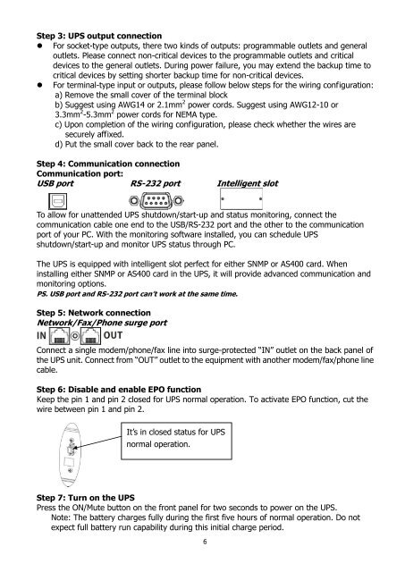
USB port RS-232 port Intelligent slot<br />
To allow for unattended UPS shutdown/start-up and status monitoring, connect the<br />
communication cable one end to the USB/RS-232 port and the other to the communication<br />
port of your PC. With the monitoring software installed, you can schedule UPS<br />
shutdown/start-up and monitor UPS status through PC.<br />
The UPS is equipped with intelligent slot perfect for either SNMP or AS400 card. When<br />
installing either SNMP or AS400 card in the UPS, it will provide advanced communication and<br />
monitoring options.<br />
PS. USB port and RS-232 port can’t work at the same time.<br />
Step 5: Network connection<br />
Network/Fax/Phone surge port<br />
Connect a single modem/phone/fax line into surge-protected “IN” outlet on the back panel of<br />
the UPS unit. Connect from “OUT” outlet to the equipment with another modem/fax/phone line<br />
cable.<br />
Step 6: Disable and enable EPO function<br />
Keep the pin 1 and pin 2 closed for UPS normal operation. To activate EPO function, cut the<br />
wire between pin 1 and pin 2.<br />
It’s in closed status for UPS<br />
normal operation.<br />
Step 7: Turn on the UPS<br />
Press the ON/Mute button on the front panel for two seconds to power on the UPS.<br />
Note: The battery charges fully during the first five hours of normal operation. Do not<br />
expect full battery run capability during this initial charge period.<br />
6