Olympus EHT & FHT Research Microscopes instruction manual
Olympus EHT & FHT Research Microscopes instruction manual
Olympus EHT & FHT Research Microscopes instruction manual

Create successful ePaper yourself
Turn your PDF publications into a flip-book with our unique Google optimized e-Paper software.
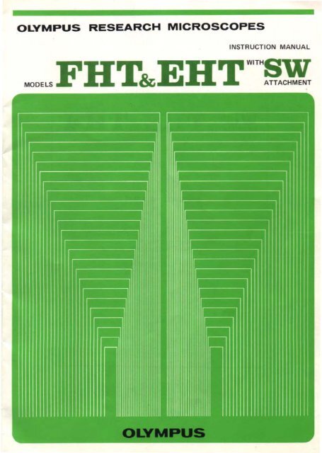
OLYMPUS RESEARCH MICROSCOPES<br />
INSTRUCTION MANUAL<br />
MODELS<strong>FHT</strong>&<strong>EHT</strong>WITH§W:
INSTRUCTION MANUAL<br />
OLYMPUS RESEARCH MICROSCOPES<br />
MODELS<br />
<strong>FHT</strong>&<strong>EHT</strong>:~~:~~<br />
TABLE OF CONTENTS<br />
I. STANDARD EQUIPMENT " 2<br />
II. SPECiFiCATiONS 4<br />
Ill. IDENTIFICATION OF VARIOUS COMPONENTS 5<br />
IV. DESCRIPTION OF EACH COMPONENT 6<br />
V. OPERATING THE MICROSCOPE 14<br />
VI. OPTICAL CHARACTERiSTICS ...............•...... ·19
I<br />
STANDARD EQUIPMENT<br />
Before assembly, please check your standard outfit, which consists of<br />
the following items:<br />
1. Model <strong>FHT</strong><br />
, ) Binocular Tube Versions<br />
Model No. Eyepieces Objectives Stage<br />
<strong>FHT</strong>-521<br />
Bi P7x, Bi WF lOx,<br />
Bi P15x, paired<br />
Ach 4x,Ach lOx,<br />
Ach 40x.<br />
Ach l00x (oill<br />
Condenser<br />
Total<br />
magnification<br />
N.A. 28x-<br />
1.25 1500x<br />
<strong>FHT</strong>-522<br />
Bi P7x, Bi High-Eye- Ach 4x.Ach lOx, FrS<br />
N.A. 28xpointWF<br />
10x,Bi P15x, FI 40x, FI 100x ISquare<br />
1.40 2000x<br />
Bi K20x. paired loill mechani·<br />
<strong>FHT</strong>-523<br />
cal stage<br />
Bi P7x, Bi High-Eye- Plan 4x. Plan lOx,<br />
with left N.A. 28xpointWF<br />
lOx. BiP15x. Plan 40x,<br />
& right 1.40 2000x<br />
Bi K20x, paired Plan loox loill<br />
hand<br />
coaxial N.A.<br />
Plan4x, Plan lOx.<br />
controls) 0.85<br />
<strong>FHT</strong>-523-<br />
Bi SW10x, paired Plan 20x, Plan40x<br />
with 40x-<br />
SW SW Plan looxloill aux. con l000x<br />
denser<br />
lens<br />
2} Trinocular Tube Versions<br />
Model No. Eyepieces Objectives Stage<br />
Bi P7x, BiWF10x,<br />
Bi P15x. paired Ach 4x, Ach lOx,<br />
<strong>FHT</strong>-531 Photo eyepieces: Ach 40x,<br />
FK2.5x, FK3.3x Ach 100x (oill<br />
FK5x,FK6.7x, leach<br />
<strong>FHT</strong>-532<br />
Bi P7x, Bi High-Eyepoint<br />
WF10x, Bi P15x,<br />
Bi K20x, paired<br />
Photo eyepieces:<br />
FK2.5x, FK3.3x.<br />
FK5x,FK6.7x,l each<br />
Ach4x,Ach lOx,<br />
FI40x,Fll00x<br />
loill<br />
Bi P7x, Bi High-Eye-<br />
point WF lOx, Bi P15x,<br />
Plan4x, Plan lOx.<br />
Bi K20x. paired<br />
<strong>FHT</strong>-533<br />
Plan 40x,<br />
Photo eyepieces:<br />
Plan l00x loill<br />
FK2.5x, FK3.3x,<br />
FK5x,FK6.7x,l each<br />
<strong>FHT</strong>-533-<br />
SW<br />
SW10x paired<br />
Photo eyepieces:<br />
FK2.5x, FK3.3x,<br />
FK5x,FK6.7x,l each<br />
Plan4x,Planl0x,<br />
Plan 20x.Plan40x,<br />
SWPlan looxloill<br />
Condenser<br />
Total<br />
magnification<br />
N.A. 28x-<br />
1.25 1500x<br />
FrS<br />
(Square<br />
mechani- N.A. 28xcal<br />
stage 1.40 2000x<br />
with left<br />
& right<br />
hand<br />
coaxial<br />
controls)<br />
N.A. 28x-<br />
1.40 2000x<br />
N.A.<br />
0.85<br />
with 40xaux.<br />
con· looox<br />
denser<br />
lens.<br />
Other items supplied with each version:<br />
Spare Bulbs,6V.5A, TB-' _. _. .. 2pcs.<br />
F ilter(blue) . . . . . . . . . . . . . . . . . . . . . . . .. , pc.<br />
Filter Mount (provided only with achromatic/aplanatic condenser) 1pc.<br />
Wooden Carrying Case. .<br />
1pc.<br />
Certificate . . . . . 1pc.<br />
2
2. Model <strong>EHT</strong><br />
, ) Binocular Tube Version<br />
Model No. Eyepieces Objectives Stage<br />
Can·<br />
denser<br />
Total<br />
magnification<br />
Ach4x, Ach lOx.<br />
Bi P7x, Bi WF10x.<br />
N.A. 28x-<br />
<strong>EHT</strong>-421 Ach 40x.<br />
8i P15x, paired<br />
1.25 1500x<br />
Ach loox (oill<br />
CrS·VH<br />
Bi P7x, BI High·Eye· Ach4x. Ach lOx ISquare<br />
N.A. 28x-<br />
<strong>EHT</strong>-422 pointWFl Ox. Bi Pl 5x. FI 40x. FI loox mechani-<br />
1.40 2000x<br />
Bi K20x. paired loill cal stage<br />
with coaxial<br />
low N.A. 28x-<br />
Bi P7x, Bi High·Eye- Plan 4x. Plan lOx.<br />
<strong>EHT</strong>-423 pointWF 1Ox.Bi Pl 5x. Plan 40x.<br />
drive 1.40 2000x<br />
Bi K20x. paired Plan loox loill<br />
controls)<br />
N.A.<br />
0.85<br />
Plan 4x. Plan lOx.<br />
<strong>EHT</strong>-423· with 40x-<br />
Bi SW10x. paired Plan20x. Plan40x,<br />
SW<br />
aux. con· looox<br />
SWPlan looxloill<br />
denser<br />
lens<br />
2) Trinocular Tube Version<br />
Model No. Eyepieces Objectives Stage<br />
Bi P7x. Bi WF lOx,<br />
Bi P15x. paired. Ach 4x. Ach lOx,<br />
<strong>EHT</strong>-431 Photo eyepieces : Ach40x,Achloox<br />
FK2.5x, FK3.3x, (oill<br />
FK5x,FK6.7x,1 each<br />
<strong>EHT</strong>-432<br />
Bi P7x. Bi High·EyepointWF10x,<br />
Bi P15x,<br />
Bi K20x, paired.<br />
Photo eyepieces:<br />
FK2.5x, FK3.3x,<br />
FK5x, FK6.7x, 1each<br />
Ach4x,Ach lOx,<br />
FI 40x. FI loox<br />
(oill<br />
Bi P7x, Bi High·Eye-<br />
pointWF10x, Bi Pl 5x,<br />
Plan 4x, Plan lOx,<br />
<strong>EHT</strong>-433 Bi K20x, paired. Plan 40x,<br />
Photo eyepieces :<br />
Plan loox (oil)<br />
FK2.5x, FK3.3x,<br />
FK5x, FK6.7x,l each<br />
<strong>EHT</strong>·433·<br />
SW<br />
Bi SW lOx, paired.<br />
Photo eyepieces:<br />
FK2.5x, FK3.3x<br />
FK5x, FK6.7x,l each<br />
Plan4x, Plan lOx,<br />
Plan 20x,Plan40x,<br />
SWPlan lOOx(oill<br />
Condenser<br />
Total<br />
magni·<br />
fication<br />
N.A. 28x-<br />
1.25 1500x<br />
CrS·VH<br />
(Square N.A. 28xmechani-<br />
1.40 2000x<br />
cal stage<br />
with low<br />
drive<br />
controls)<br />
N.A. 28x-<br />
1.40 2000-<br />
N.A.<br />
0.85<br />
with 40xaux.<br />
con- 1000x<br />
denser<br />
lens<br />
Other items supplied with each version:<br />
Spare Bulbs,6V,5A.TB·'<br />
2pcs.<br />
Filler(blue) . . . . . . . . . . . . . . . . . . . . . . . . . . . . . . . . . . . . .. , pc.<br />
Filter Mount(provided only wilh achromatic/aplanalic condenser) 1pc.<br />
Wooden Carrying Case.<br />
1pc.<br />
Certificate . . . . . . . . 1pc.<br />
3
II<br />
SPECIFICATIONS<br />
~<br />
--------<br />
Focusing<br />
<strong>FHT</strong><br />
<strong>EHT</strong><br />
Vertical stage movement. Vertical stage movement.<br />
coax ial coarse and fine ad· separate coarse and fine<br />
justments, with automatic adjustments. with autopre·focusing<br />
lever.<br />
matic pre-focusing lever.<br />
Coarse Devetait slideways, rack and pinion type:<br />
adjustment adjustment range 32.5 mm<br />
Fine<br />
adjustment<br />
Adjustment ragne 1.2mm. Adjustment range 1.2mm,<br />
graduated in increments of graduated in increments of<br />
1 micron. 2 microns.<br />
Micrascope<br />
Tungsten lamp, 6V. 5A, with centering device and built·in<br />
Stand Light transformer.<br />
source Auxiliary lenses for low, medium and high power<br />
objectives.<br />
Revolving Quintuple, on ball bearings. Engravings. coded A to E.<br />
nosepiece to facilitate objective insertion.<br />
Condenser With condenser centering device and rack·and-pinion<br />
mount height adjustment. Height displacement 23.5mm.<br />
Tube inclination 45-, rotatable 360-, both eyepiece tubes<br />
provided with diopter and tube length adjustments,<br />
Binocular<br />
except Bi-SW observation tube inclined 30-, and diopter<br />
Obsertube<br />
difference can be adjusted by the SW eyepiece tube.<br />
vation<br />
I nterpupillary distance adjustment from 56mm to 74mm.<br />
Tubes<br />
Tube inclination 45·, rotatable 360·, both eyepiece tubes<br />
provided with diopter and tube length adjustments, except<br />
Trinocular Tr-SWobservation tube inclined 30·, and diopter difference<br />
tube can be adjusted by the SW eyepiece tube. Interpupillary<br />
distance adjustment from 56mm to 74mm, with photo<br />
tube. Light path selector lever.<br />
FrS<br />
CrS·VH<br />
Rotatable graduated mech· Rotatable graduated mech·<br />
anical stage with horizontal anical stage with low drive<br />
Stages<br />
drive controls, movement controls, movement range<br />
range 44mm x 76mm. Ver· 52mm x 76mm. Vernier<br />
nier scales reading to O. 1mm scales reading to 0.1mm.<br />
Achromatic! NA 1.40, with decenterable aperture iris diaphragm and<br />
aplanatic graduated scale.<br />
condenser<br />
Can·<br />
Abbe N.A. 1.25, with aperture iris diaphragm and swing-out<br />
densers condenser filter mount.<br />
CO-4<br />
condenser<br />
N.A. 0.85, for super widefield of view, with variable<br />
aperture iris diaphragm, filter holder and auxiliary<br />
condenser lens.<br />
Photo Eyepieces F K<br />
The new photo eyepieces F K are specially designed for photomicrography<br />
with the <strong>Olympus</strong> Photomicrographic System Camera Model<br />
PM-10 (optional). The eyepiece powers available are 2.5x, 3.3x, 5x<br />
and 6.7x. Each magnification is computed to focus an image at a projection<br />
length of 125mm - the same plane as the 35mm film plane, thus<br />
compensating spherical aberration. The respective magnifications<br />
are engraved on the FK eyepieces: Total magnification of a picture<br />
when the F K eyepiece is used. is formulated as follows:<br />
Total magnification with 35mm film = Objective power x FK eyepiece<br />
power.<br />
The formula below, however. will be applied in case the camp.ra<br />
adapter with relay lens, model PM-D L, is used for larger format<br />
camera backs:<br />
Total magnification of.large format picture = Objective power x FK<br />
eyepiece power x3.<br />
4
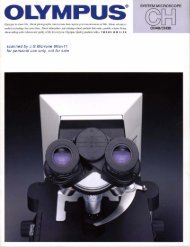
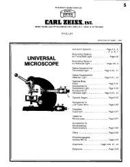
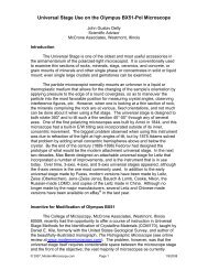
III<br />
IDENTIFICATION<br />
OF VARIOUS COMPONENTS<br />
Eyepiece<br />
Trinocular Observation Tube<br />
Revolving<br />
Nosepiece<br />
Limb<br />
Objective<br />
5'"",<br />
Conden~r<br />
Voltmeter<br />
Voltage<br />
Adjustment<br />
Knob<br />
<strong>FHT</strong>·533<br />
5
IV<br />
DESCRIPTION<br />
OF EACH COMPONENT<br />
A. Mic:roMlOpe Sund<br />
1. Limb 8nd Focusi"9 Mech..,ism<br />
The limb is securely attached to the sturdy base and supports the observation<br />
tube, stage, condenser, revolving nosepiece and focusing mechanism.<br />
The focusing mechanism includes the coarse and fine adjustments and an<br />
automatic pre-focusing lever. This lever is provided to prevent possible<br />
contact between specimen and objective as well as to simplify coarse<br />
focusing. The lever is locked after coarse focus has been accomplished.<br />
This prevents further upward travel of the stage and automatically provides<br />
a limiting stop if the stage is lowered then raised again. The<br />
automatic pre-focusing lever does not restrict fine focusing.<br />
The filter mount is plaoed on the light exit of the illuminator base.<br />
Stage Clamping Lever<br />
Co_<br />
Adjustment Knob<br />
Fine<br />
Adjustment Knob<br />
Automatic<br />
Pre-focusing Lever<br />
AuxiI iory Lens<br />
Shifting Lever<br />
Fillllr Mount<br />
Light Exit<br />
<strong>FHT</strong><br />
Coane<br />
Adjustment Knob<br />
Fine<br />
Adjustment Knob<br />
2. Condenser<br />
The condenser may be mounted on the condenser mount by first<br />
inserting the condenser into the condenser mount from below, aligning<br />
the positioning dots on the condenser and condenser mount, and then<br />
clamping with the clamping screw. Condenser centration can be<br />
accomplished by means of two centering knobs. Vertical movement of<br />
the condenser can be adjusted by the condenser height adjustment knob.<br />
The condenser has an excellent resolving power, dry or oil immersion,<br />
from 4x to 100x magnification objectives. When using the 100x<br />
objective, the distance between condenser and specimen should be<br />
filled with immersion oil.<br />
Note: For use with the achromaticlaplanatic condenser N.A. 1.40, the<br />
filter mount is placed on the light exit of the illuminator base, while<br />
either the Abbe N.A. 1.25 or N.A. 0.85 condenser incorporates its<br />
own filter mount. When the N.A. 0.85 condenser is used for super<br />
widefield observation, keep the auxiliary condenser lens slipped on the<br />
light exit on the base.<br />
The slide clamping screw permits simultaneous locking of slide and<br />
6
otation of condenser and the slide lever allows decentering and rotating<br />
the aperture iris diaphragm for obligue illumination.<br />
• Abbe Conden5el", N.A. 1.25<br />
Abbe COI"denser--------<br />
Condenser Mount<br />
Condenser Clamping<br />
Screw<br />
Centering Knob<br />
Filter Moun't-~--'<br />
Aperture Iris<br />
l..::>..._---- Diaphragm<br />
Control lever<br />
,,~~- Alignment Dots<br />
• Achromatic/aplanatic Condenser, N.A. 1.4<br />
Achromaticl<br />
aplanatic<br />
Condenser------<br />
Condenser<br />
Clamping<br />
Screw ----~-.<br />
Centering Knob<br />
Aperture Iris<br />
Diaphragm<br />
Cuntrol Aing-~-r-'<br />
/ Condenser Mount<br />
Slide Clamping<br />
Screw<br />
~...... Alignment Dots<br />
----Slide Lever<br />
• CD-4 Condenser, N.A. 0.85<br />
Condenser<br />
Condenser MOllnt<br />
Condenser Clamping<br />
Screw<br />
Centering Knob<br />
Filter Mount<br />
Alignment Dots<br />
Aperture Iris<br />
Diaphragm Control<br />
Leve<<br />
7
3. Microscope Base and· Light Source<br />
1) Microscope Base<br />
The lamp house is built onto the base. The lamp socket is clamped to<br />
the lamp house with a damping screw. The tight path is selected with<br />
the auxiliary lens shifting lever for high, medium and low magnification<br />
of objective in use.<br />
...__..<br />
Objective<br />
4x<br />
lOx<br />
20x-l00x<br />
For<br />
Observation<br />
Observ.<br />
Lever Position<br />
Fo,<br />
Photomicrography<br />
L<br />
H<br />
It is generally recommended to set the lever to the position marked with<br />
"Observ." (equivalent to position L) for brightfield observation with<br />
all the objectives from 4x through 100x. In phase contrast or darkfield<br />
observation, where in tenser light is required, however, it is recommended<br />
to set it to position M or H according to objective magnification as in<br />
case with photomicrography.<br />
Voltage<br />
Adjustment Knob<br />
Grounding terminal<br />
..::::::;::;",::::~--Line Voltage<br />
Adjustment Screw<br />
o Voltage Adjustment<br />
The minimum voltage required for the light source can be varied qv<br />
means of the line voltage adjustment screw provided at the back of the<br />
microscope base in accordance with the line voltage and frequency,<br />
since a silicon controlled rectifier (SeRl is .adopted in the dimmer<br />
circuitry.<br />
At the bottom of the base is a voltage selector switch, which can be<br />
turned with a coin, to correspond with the voltage of main supply<br />
(11 OV, 120V, 220V or 240Vl. The transformer is built in the base and<br />
switched on and off with the voltage adjustment knob, which also<br />
controls the bulb voltage from 0 to lOV.<br />
8
•<br />
2 ) Light Source<br />
The light source consists of lamp house CD and lamp socket ® .<br />
The lamp socket is provided with two coaxial lamp centering knobs<br />
@ _ The Jamp socket can be moved back and forth along the optical<br />
axis to eliminate uneven illumination in the field of view.<br />
a. Electric Connection<br />
1) Insert the jacks of the lamp cord into the low voltage outlet at<br />
the back of microscope base.<br />
2) Insert the plugs of the line cord into the tine cord socket and the<br />
AC po......er outlet respectively.<br />
b. Adjustment of Line Voltage<br />
1) Turn the voltage adjustment knob clockwise to position ON.<br />
2) If the bulb is dimmly lit. the line voltage is proper, and you have<br />
only to manipulate the voltage adjustment knob in order to obtain<br />
optimum light intensity. with no need to further proceed to the<br />
following procedure 3).<br />
3) Even after the voltage adjustment knob is turned on, if the bulb<br />
does not light or lights up bright immediately after switching on,<br />
rotate gradually the line voltage adjustment screw (at the back of<br />
the base) with a coin, until the lamp dims.<br />
o According to the fluctuations of line voltage and frequency<br />
(SO/60Hz), minimum voltage required for lighting the bulb<br />
varies; if the bulb does not light at all or lights up immediately<br />
after switching on, re-adjustment of the line voltage screw is<br />
necessary to dim the bulb.<br />
Note: For light intensity adjustment after dimming the bulb,<br />
use the voltage adjustment knob on the side of the base.<br />
c. Attach the tamp socket.<br />
1) Loosen the clamping screw
4. Low Voltage Indication<br />
~' ~ 1<br />
5 ;; 1 8 9 10<br />
Meter indicates 3V. Meter indicates 6V,<br />
As the voltage adjus~ment knob is turned clockwise, the red zone<br />
advances as shown above. Use·the upper scale of the meter to read from<br />
oto 5V, and the lower scale to read from 5V to lOV. Avoid prolonged<br />
use at voltages above 6V.<br />
Lamp Replacement<br />
l 1) Loosen the socket clamping screw and slide out the socket.<br />
l2l Remove the bulb by slightly depressing it against the seat and<br />
then rotating it in a counterclockwise direction.<br />
(3l Insert a replacement bulb in reversed order.<br />
Before use, wipe off thoroughly any fingerprints or stains on<br />
the bulb.<br />
5. Revolving Nosepiece<br />
The Quintuple revolving nosepiece rotates on ball bearings.<br />
A knurled ring is provided for slip-free and smooth rotation.<br />
Each objective clicks Into position accurately, maintaining proper<br />
optical alignment. Also each objective hole is coded with the letters<br />
A, 8, C, D and E in order to indicate where the objectives should be<br />
mounted, as "A" is for 4x, "B" for lOx, "C" for 20x, "0" for 40x<br />
and "E" for 100x In addition, the observer can easily tell what<br />
power objective is being used by the color band engraved un each<br />
objective during observation.<br />
Magnification 4x 10, 20, HlQ,<br />
Color band Red Orange Yellow Brilliant green Light blue<br />
* The stage must be mounted on the microscope prior to the mount<br />
ing of objectives on the revolving nosepiece.<br />
'0
B. Observation Tubes<br />
The observation tubes are inclined 45" (except Bi·SW and Tr-SW both<br />
inclined 30°) and rotatable 360°. The tubes can be clamped in any<br />
direction with the clamping screw provided.<br />
For adjustment of interpupillary distance. hold the right and left<br />
eyepiece tubes with both hands and push the tubes together or<br />
pull them apart laterally, whichever is required, while looking at an<br />
image through the eyepieces with both eyes, until perfect binocular<br />
vision is obtained. It is good practice to memorize the individual<br />
interpupillary distance. setting. A scale for this purpose is located<br />
between the eyepiece tubes. (The mechanical tube length of the SW<br />
observation tubes is 160mm when this scale is set at 62.l The eyepiece<br />
tubes are provided with diopter and tube length adjustment rings.<br />
A light path selector lever to direct the light to observation tube or<br />
photo tube, is provided with the trinocular observation tube.<br />
Photo Tube<br />
Light Path Selector lever<br />
;:::===--- Diopter Adjustment Rings<br />
Clamping Screw---tllIO'lt__<br />
~Knurled Ring<br />
Eyepiece Tube<br />
-r- Eyepiece Positioning Groove<br />
Interpupillary<br />
Distance<br />
Scale<br />
Knurled Ring,--"'-\<br />
Clamping Screw<br />
11
Photo Tube<br />
Clamping Screw -~~~~~~-.!J!!~~~-<br />
Ujht Path<br />
Se ector Lever<br />
C. Stages<br />
1. Square Mechanical Stage FrS<br />
This is a square coaxial drive control mechanical stage with interchangeable<br />
mount. The specimen is moved by means of horizontal drive controls<br />
on both sides of the stage. The larger control knob is for north-south (Y)<br />
movement of the specimen, and the smaller control knob is for east-west<br />
(X) movement.<br />
The working range of the specimen holder is:<br />
North-south excursion ... 44mm<br />
East-west excursion. . .. . 76mm<br />
Each control is provided with a scale (0-50 for Y excursion, 50-120 for<br />
X excursion) and a vernier, reading to 0.1 mm. Stage rotation can be<br />
clamped by a clamping screw. The stage may be used as a plain stage by<br />
removing the specimen holder assembly.<br />
Graduated Scale for<br />
North-South Movement<br />
-------<br />
Graduated Scale for<br />
East-West Movement<br />
Specimen Holder<br />
Clampinq Screws for<br />
SpeCimen Holder<br />
Stage Rotation<br />
Clamping Screw<br />
North-South Movement<br />
Control Knob<br />
East-West Movement<br />
Control Knob<br />
Movement<br />
Control Kno<br />
* The stage may be mounted on the microscope in reversed position, as<br />
shown in the picture above, right, to obtain increased rotation.<br />
'2
2. Square Mechanical Stage with Low Drive Controls CrS-VH<br />
The specimen is moved by means of coaxial low drive control knobs<br />
which are provided on'the stage vertically.<br />
The working range of the specimen holder is:<br />
North-south excursion , 52mm<br />
East-west excursion 76mm<br />
Each control is provided with a scale 10-60 for Y excursion, 6O~13)<br />
for X excursion) and a vernier, reading to 0.1 mm.<br />
Stage rotation: After bring the specimen slide in position, move the center<br />
of the specimen slide into the optical axis. then rotate the stage horizontally.<br />
The stage rotation can be clamped by means of a clamping screw.<br />
The stage may be used as a plain stage by removing the specimen holder.<br />
Graduated Scale<br />
for East-West<br />
Movement __....'"<br />
North.south<br />
Movement<br />
Control Knob<br />
East-West<br />
Movement<br />
Control Knob<br />
'--<br />
Specimen Holdel"<br />
Clamping Screw for<br />
Stage Rotation<br />
~ ~=~l",:;;e;';f,or Rotation<br />
r uat Scale for<br />
~"'onh-SolJthMovemeoJ<br />
Stage Clamping lever<br />
3, Square Mechanical Stage with Low Drive Controls Cs-VH<br />
This mechanical stage is operated by coaxial low drive controls on<br />
rack-and-pinion for north-south and east-west movements. The working<br />
range of the specimen holder IS the same as that of the CrS-VH.<br />
4, Square Coaxial Mechanical Stage CS<br />
Thp- mechanical stage CS is operated by coaxial horizontal control<br />
knobs with rack-an"d-pinion for north-south movement and a lead screw<br />
for east-west movement.<br />
5. Mount the Mechanical Stage<br />
1) Lower the condenser mount as far as possible with the condenser height<br />
adjustment knob.<br />
2) Lower the stage dovetail slide all<br />
the way with the coarse adjustment<br />
knobs.<br />
3) Insert the dovetail mount of the<br />
stage slowly into the stage dovetail<br />
slide all the way down. and lock<br />
the stage with the locking lever<br />
provided on the dovetail mount<br />
of the stage.<br />
13
y<br />
OPERATING<br />
THE MICROSCOPE<br />
A. Interpupillary Distance and Diopter Adjustments<br />
In order to obtain perfect binocular vision through the eyepieces, it is<br />
necessary to adjust interpupillary distance and diopter difference in eye<br />
acuity; otherwise, long time observation would put considerable strain on<br />
the obser'.;er's eyes.<br />
1. Interpupiltary 0 istance Adjustment<br />
(1) Hold the (igh t and lef t eyepiece tubes with both hands and push the<br />
tubes together, or pull them apart laterallY,whichever is required,<br />
while looking through the eyepieces with both eyes, until perfect<br />
binocular vision is obtained.<br />
(2) Memorize your interpupillary distance setting. Scale CD is provided<br />
for this purpose, located between the eyepiece tubes.<br />
* This interpupillary distance adjustment is necessary each time<br />
observers are changed.<br />
Re-focusing is also necessary whenever the<br />
interpupillary distance is changed.<br />
2. Diopter Adjustment<br />
a. For F HT and <strong>EHT</strong><br />
(1) Rotate the diopter ring ® on the right eyepiece tube to match the<br />
scale on the ring to your interpupillary distance setting which you<br />
obtained from scale CD as described in the preceding paragraph<br />
1-121<br />
(2) Look at the image through the<br />
right eyepiece with your right<br />
eye and focus on the specimen<br />
with the fine adjustment knobs.<br />
(3) Next, look at the image through<br />
the left eyepiece with your left<br />
eye and rotate the diopter ring@<br />
to focus on the specimen without<br />
using the coarse and fine<br />
adjustment knobs.<br />
b. For <strong>FHT</strong>-SW and <strong>EHT</strong>-SW<br />
Each SW eyepiece is provided with<br />
diopter ring for adjustment of your<br />
diopter difference.<br />
(1) Rotate the diopter ring on the<br />
right eyepiece tube to obtain<br />
a clear image of the field of<br />
view in the eyepiece.<br />
(2) Look at the image through the<br />
right eyepiece with your right<br />
eye and focus on the specimen<br />
with the fine adjustment knobs.<br />
(3) Next,look at the image through<br />
the left eyepiece with your left<br />
eye and rotate the diopter ring<br />
to focus on the specimen without<br />
using the coarse and fine<br />
adjustment knobs.<br />
14
B. Center the Condenser and the Light Bulb<br />
After all necessary components are attached to the microscope stand<br />
properly and securely, it is essential to center the condenser and the<br />
light bulb before the microscope is put in operation.<br />
1. First, make sure that all electrical conne~tions are done property,<br />
then turn the switch in the microscope base to the ON position.<br />
The lamp will light up. By raising the voltage progressively, you can<br />
ascertain that the bulb is on.<br />
Adjust light intensity to suit your requirements.<br />
2. Swing the auxiliary lens shifting lever on the illuminator base to position<br />
Observ.<br />
3. Place a specimen on the stage and use the objective lOx to bring the<br />
specimen in focus.<br />
o<br />
o<br />
Out of center.<br />
Centered.<br />
Opened fu lIy.<br />
4. Stop down the field iris diaphragm with the field iris diaphragm<br />
control provided on the microscope base. A slightly blurred image<br />
of the field iris diaphragm can now be seen in the field of view.<br />
5. Move the condenser up and down with the condenser height<br />
adjustment knob to focus on the image of the field iris diaphragm.<br />
;(;rvvv,<br />
\"IJU
C. Use of Iris Diapnragms<br />
A field iris diaphragm as well as an aperture<br />
iris diaphragm is provided on the microscope.<br />
The field iris diaphragm is built into the<br />
base and the aperture iris diaphragm is part<br />
of the condenser.<br />
1. Field Iris Diaphragm<br />
The field iris diaphragm controls the diameter<br />
of the ray bundle impinging on the<br />
specimen surface and thus increases image<br />
definition. Stop down the field iris diaphragm<br />
while looking through the eyepiece.<br />
An image of the iris diaphragm will appear<br />
within the field. Now open the field diaphragm<br />
until its diameter is just slightly<br />
larger than the diameter of the field of view.<br />
• When particularly clearer definition of<br />
an image is required in the center of the<br />
field of view stop down the iris diaphragm as<br />
narrow as shown in the picture at bottom.<br />
• The image of the field iris diaphragm is conjugated on the specimen's<br />
surface, so that the diameter of the field iris diaphragm changes<br />
according to the change of the objective power. By the same token<br />
with every change of the eyepiece the field number will be varied,<br />
which necessitates re-adjustment of the diameter at the field diaphragm.<br />
•<br />
2. Aperture Iris Diaphragm<br />
An aperture iris diaphragm opened too<br />
wide impairs image con·trast due to internal<br />
reflections and related factors. On the<br />
other hand, if the diaphragm is stopped<br />
down exce"->5ivcly, rC50lution is unduly<br />
reduced. It is therefore suggested to match<br />
the opening of the aperture iris diaphragm<br />
to the numerical aperture of the objective<br />
in use, in order to achieve maximum<br />
60-10"<br />
,,.,,<br />
objective performance. For that purpose<br />
simply set the numerical aperture scale on<br />
the condenser to the numerical apeflure of<br />
the objective in use.<br />
However, since microscopic specimens generally are low in contrast,<br />
their image lacks contrast if the objective is usecl with its full numerical<br />
aperture. Therefore. il is occasionally preferable to stop down the aperture<br />
iris diaphragm slightly more than indicated by the objective N.A. This<br />
will result in increased image contrast, larger depth of focus and a flatter<br />
field. On the other hand, stopping down too much impairs resolution.<br />
An aperture setting of O.6-0.7x the N.A. of the objective is recommended.<br />
If the N.A. of the objective is 1, for instance, you can set the scale to<br />
0.6-0.7.<br />
•<br />
16
D. Tension Adjustment of Coarse Adjustment Knobs<br />
While the coarse adjustment motion is normally sliff and heavy, it is<br />
freely adjustable for either heavy or light movemenl depending on the<br />
observer's preference. To adjust the tension hold lhe two coarse adiustment<br />
knobs with your both hands and rolate them in the opposite direction<br />
at the same time.<br />
E. ParfocalObjectives<br />
Since alt objectives are par/oeal. only a minimum of fine adJuslment control<br />
is required when you change the objectives.<br />
Focusing Procedure:<br />
1) Operate the fine adjustment knob to bring the line adjustment indicator<br />
line to the center of the fine adjustment range.<br />
2) Place thp. lOx objective in position<br />
3) Bring the specimen as closely as possible to the objective with the<br />
coarse adjustment knobs.<br />
4) While looking through the eyepiece, lower the stage slowly and focus<br />
on the specimen.<br />
5) Turn the revolving nosepiece to bring the objective to be used into<br />
the light path.<br />
F. Use of Immersion Optical Components<br />
1. Immersion Objectives:<br />
1) Focus on the specimen with a low-power objective.<br />
21 Put a drop of immersion oil on both the specimen and the objective<br />
front lens.<br />
3) Turn the revolving nosepiece to bring the immersion objective into<br />
the light path, and focus with the fine adjustment knob.<br />
2. Immersion Condensers:<br />
1) Remove the specimen from the mechanicul stnge and place a drop of<br />
immersion oil on the front lens of the condenser.<br />
2) Place the specimen on the mechanical stage and slowly raise the·condenser<br />
until firm contact with the underside of the specimen slide is<br />
made. Care should be taken to prevent oil bubbles from forming in<br />
the oil film between condenser and specimen slide.<br />
3. After Use<br />
Carefully wipe off the immersion oil deposited on the lens surfaces wi th<br />
gauze moistened with xylene.<br />
Never leave oil on the lens surfaces after use as oil remnants will<br />
seriously impair the performance of the lens systems.<br />
17
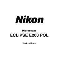
G. Oblique Illumination<br />
The achromatic!aplanatic condenser N.A. 1.40 has<br />
extremely high resolving power and will give the<br />
operator satisfactory results even when used dry.<br />
When using objectives lOOx, the condenser should<br />
be immersed. The condenser can be used with all<br />
objectives from 4x and up. Oblique illumination<br />
will further improve resolving power.<br />
1. With oblique illumination, the resolving power<br />
can be doubled. As against the normal (central)<br />
illumination where the light beams are parallel<br />
to the optical axis of the microscope, oblique<br />
illumination provides light bundles at an angle<br />
to the optical ax is.<br />
The illuminating light proceeds from below with<br />
an inclination to the specimen, which will cause<br />
not only the normal transmitted beam but also<br />
more of the refracted light to enter the objective.<br />
This will double the resolving power as compared<br />
with central illumination. The drawing on the<br />
right hand side illustrates the oblique illumination<br />
system.<br />
The cross-hatched area represents the cone of<br />
light.<br />
C: Optical axis Ob: Objective~<br />
Cd: Condenser r: Iris diaphragm<br />
c<br />
2. Procedure<br />
1) Stop down the aperture iris diaphragm.<br />
2) Loosen the clamping screw and pull out the<br />
aperture diaphragm with the slide lever.<br />
The direction of diaphragm displacement<br />
should be at right angles to the specimen<br />
detail to be observed.<br />
For example, jf it is desired to identify two<br />
parallel details very close to each other as two<br />
separate Jines, the aperture diaphragm is<br />
moved at right angles to the details. If iden·<br />
tification of two points is desired, the<br />
diaphragm is moved parallel to the straight<br />
line. connecting the two points.<br />
3) Adjustment of the diaphragm slide and<br />
diaphragm diameter while looking through<br />
the eyepiece resolves the two lines or points<br />
and permits very detailed observation of tfie<br />
structure.<br />
3. Observation of Overall Area Possible<br />
.-----<br />
---.<br />
•<br />
~s<br />
CD Resolving power<br />
increases in this<br />
direction.<br />
® Resol'Ving power<br />
decreases in this<br />
direction.<br />
a Article to be identified<br />
Obl ique illumination is effective only when the S~ Sliding direction of iris<br />
illuminating light is directed at right angles to<br />
the specimen<br />
In order to identify individual specimen details, therefore, it is necessary<br />
to adapt the direction of diaphragm displacement perpendicl:llar to<br />
the direction of the specimen detail to be observed.<br />
Diaphragm rotation through 150 0 is possible with the achromatic!<br />
aplanatic condenser. Stage rotation provides further possibility of<br />
directional adaptation.<br />
18
H. eare for Storing<br />
Moisture and dust are the most deadly factors to microscopes. Since both<br />
moisture and dust are found in most laboratories,microscopes should<br />
be kept in containers immediately after use. If this is not possible. they<br />
should be covered with the vinyl dust cover provided.<br />
As for objectives and eyepieces, it is best to keep them in desiccators.<br />
Failing this, they should be kept in cases containing such desiccants as<br />
silica gel. After.the eyepieces are removed from the microscope. the vacant<br />
eyepiece sleeves should be covered with protective caps. By no means<br />
should a microscope be disassembled for repairs. This should be left to<br />
the <strong>Olympus</strong> repair service.<br />
<strong>Microscopes</strong> must always be kept clean. Fioe dust on parts that cannot<br />
be reached by hand should be blown or wiped off by means of an air<br />
blower or a clean feather.<br />
VI<br />
OPTICAL<br />
CHARACTERISTICS<br />
A. Eyepieces (P, WF, K) x Objectives (Ach, FI, Plan)<br />
S,_ N~ Acnromlli( Fluorite Plan AchromatIC<br />
IMgnil'catiOfl 0, '0, 00,<br />
""', '0, '00, 0,<br />
,."<br />
Numerical Aoe.tu.
MEMO<br />
20
'----------------------------------'Prmte In<br />
Japan 7