KT-PC4216 - GTO Security Technologies
KT-PC4216 - GTO Security Technologies
KT-PC4216 - GTO Security Technologies

You also want an ePaper? Increase the reach of your titles
YUMPU automatically turns print PDFs into web optimized ePapers that Google loves.
<strong>KT</strong>-<strong>PC4216</strong><br />
Output Module<br />
/<br />
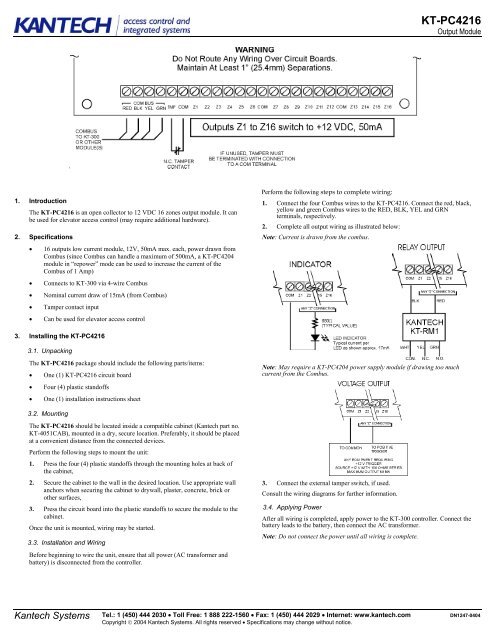
1. Introduction<br />
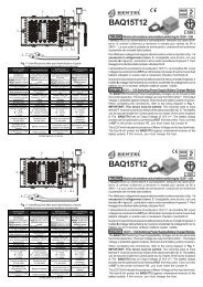
The <strong>KT</strong>-<strong>PC4216</strong> is an open collector to 12 VDC 16 zones output module. It can<br />
be used for elevator access control (may require additional hardware).<br />
2. Specifications<br />
• 16 outputs low current module, 12V, 50mA max. each, power drawn from<br />
Combus (since Combus can handle a maximum of 500mA, a <strong>KT</strong>-PC4204<br />
module in “repower” mode can be used to increase the current of the<br />
Combus of 1 Amp)<br />
• Connects to <strong>KT</strong>-300 via 4-wire Combus<br />
• Nominal current draw of 15mA (from Combus)<br />
• Tamper contact input<br />
• Can be used for elevator access control<br />
Perform the following steps to complete wiring:<br />
1. Connect the four Combus wires to the <strong>KT</strong>-<strong>PC4216</strong>. Connect the red, black,<br />
yellow and green Combus wires to the RED, BLK, YEL and GRN<br />
terminals, respectively.<br />
2. Complete all output wiring as illustrated below:<br />
Note: Current is drawn from the combus.<br />
3. Installing the <strong>KT</strong>-<strong>PC4216</strong><br />
3.1. Unpacking<br />
The <strong>KT</strong>-<strong>PC4216</strong> package should include the following parts/items:<br />
• One (1) <strong>KT</strong>-<strong>PC4216</strong> circuit board<br />
• Four (4) plastic standoffs<br />
• One (1) installation instructions sheet<br />
Note: May require a <strong>KT</strong>-PC4204 power supply module if drawing too much<br />
current from the Combus.<br />
3.2. Mounting<br />
The <strong>KT</strong>-<strong>PC4216</strong> should be located inside a compatible cabinet (Kantech part no.<br />
<strong>KT</strong>-4051CAB), mounted in a dry, secure location. Preferably, it should be placed<br />
at a convenient distance from the connected devices.<br />
Perform the following steps to mount the unit:<br />
1. Press the four (4) plastic standoffs through the mounting holes at back of<br />
the cabinet,<br />
2. Secure the cabinet to the wall in the desired location. Use appropriate wall<br />
anchors when securing the cabinet to drywall, plaster, concrete, brick or<br />
other surfaces,<br />
3. Press the circuit board into the plastic standoffs to secure the module to the<br />
cabinet.<br />
Once the unit is mounted, wiring may be started.<br />
3.3. Installation and Wiring<br />
Before beginning to wire the unit, ensure that all power (AC transformer and<br />
battery) is disconnected from the controller.<br />
3. Connect the external tamper switch, if used.<br />
Consult the wiring diagrams for further information.<br />
3.4. Applying Power<br />
After all wiring is completed, apply power to the <strong>KT</strong>-300 controller. Connect the<br />
battery leads to the battery, then connect the AC transformer.<br />
Note: Do not connect the power until all wiring is complete.<br />
Kantech Systems<br />
Tel.: 1 (450) 444 2030 • Toll Free: 1 888 222-1560 • Fax: 1 (450) 444 2029 • Internet: www.kantech.com<br />
Copyright © 2004 Kantech Systems. All rights reserved • Specifications may change without notice.<br />
DN1247-0404
<strong>KT</strong>-<strong>PC4216</strong><br />
Output Module<br />
4. Assigning the module<br />
Follow the instructions below for assigning and programming your <strong>KT</strong>-<strong>PC4216</strong><br />
module.<br />
Follow these steps to assign the module(s):<br />
1. Establish communication between the PC and the controller,<br />
2. Remove the tamper switch wire (or only the wire if tamper switch is not<br />
used),<br />
3. A serial number should be displayed on the screen, in the same window<br />
where is the serial number is located, you should see the type of module and<br />
on which controller it is connected,<br />
4. From the software, select the functionality of the module and enter the serial<br />
number in the appropriate field (see your software reference manual under<br />
controller definition -- Assigning modules for more details).<br />
Note: Don’t forget to reconnect the tamper switch (or the wire, if there is<br />
no tamper switch).<br />
Terminal Connections<br />
Module no.: ______________________________________________________________________________________<br />
Date of installation: _______________________________________________________________________________<br />
<strong>KT</strong>-300 Name: ____________________________________________________________________________________<br />
<strong>KT</strong>-300 SITE NAME: _______________________________________________________________________________<br />
<strong>KT</strong>-300 Serial Number: _____________________________________________________________________________<br />
COMBUS (FROM):_________________________________________________________________________________<br />
COMBUS (TO): ___________________________________________________________________________________<br />
Z1: _____________________________________________________________________________________________<br />
Z2: _____________________________________________________________________________________________<br />
Z3: _____________________________________________________________________________________________<br />
Z4: _____________________________________________________________________________________________<br />
Z5: _____________________________________________________________________________________________<br />
Z6: _____________________________________________________________________________________________<br />
Z7: _____________________________________________________________________________________________<br />
Z8: _____________________________________________________________________________________________<br />
Z9: _____________________________________________________________________________________________<br />
Z10: ____________________________________________________________________________________________<br />
Z11: ____________________________________________________________________________________________<br />
Z12: ____________________________________________________________________________________________<br />
Z13: ____________________________________________________________________________________________<br />
Z14: ____________________________________________________________________________________________<br />
Z15: ____________________________________________________________________________________________<br />
Z16 _____________________________________________________________________________________________<br />
FCC & IC COMPLIANCE STATEMENT<br />
CAUTION: Changes or modifications not expressly approved by Kantech Systems Inc. could void your authority to use this equipment.<br />
This equipment generates and uses radio frequency energy and if not installed and used properly, in strict accordance with the manufacturer’s instructions, may cause<br />
interference to radio and television reception. It has been type tested and found to comply with the limits for Class B device in accordance with the specifications in Subpart<br />
“B” of Part 15 of FCC Rules, which are designed to provide reasonable protection against such interference in any residential installation. However, there is no guarantee<br />
that interference will not occur in a particular installation. If this equipment does cause interference to television or radio reception, which can be determined by turning the<br />
equipment off and on, the user is encouraged to try to correct the interference by one or more of the following measures:<br />
• Re-orient the receiving antenna<br />
• Relocate the alarm control with respect to the receiver<br />
• Move the alarm control away from the receiver<br />
• Connect the alarm control into a different outlet so that alarm control and receiver are on different circuits.<br />
If necessary, the user should consult the dealer or an experienced radio/television technician for additional suggestions. The user may find the following booklet prepared<br />
by the FCC helpful: “How to Identify and Resolve Radio/Television Interference Problems”. This booklet is available from the U.S. Government Printing Office,<br />
Washington, D.C. 20402, Stock # 004-000-00345-4. This device complies with Part 15 of the FCC rules. Operation is subject to the following two conditions: (1) this<br />
device may not cause harmful interference, and (2) this device must accept any interference received including interference that may cause undesired operation. This class<br />
B digital apparatus meets all requirements of the Canadian Interference Causing Equipment Regulations. The <strong>KT</strong>-300 is also compliant with EN55022: 1994, amendment 1:<br />
1995, Class B.<br />
Kantech Systems<br />
Tel.: 1 (450) 444 2030 • Toll Free: 1 888 222-1560 • Fax: 1 (450) 444 2029 • Internet: www.kantech.com<br />
Copyright © 2004 Kantech Systems. All rights reserved • Specifications may change without notice.<br />
DN1247-0404