High Precision Ball Bearings - Kraftmek
High Precision Ball Bearings - Kraftmek
High Precision Ball Bearings - Kraftmek

You also want an ePaper? Increase the reach of your titles
YUMPU automatically turns print PDFs into web optimized ePapers that Google loves.
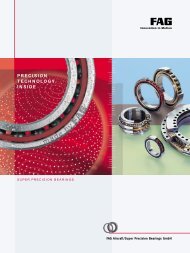
<strong>High</strong> <strong>Precision</strong><br />
<strong>Ball</strong> <strong>Bearings</strong><br />
Spindle <strong>Bearings</strong><br />
Deep Groove <strong>Ball</strong> <strong>Bearings</strong><br />
<strong>High</strong> <strong>Precision</strong> <strong>Ball</strong> <strong>Bearings</strong><br />
Hybrid <strong>Bearings</strong><br />
Special <strong>Bearings</strong>,<br />
<strong>Bearings</strong> Units<br />
Vacuum Technology,<br />
Dry Lubrication<br />
<strong>High</strong> <strong>Precision</strong><br />
<strong>Ball</strong> <strong>Bearings</strong><br />
Paul Müller Industrie<br />
GmbH & Co. KG<br />
Äußere Bayreuther Straße 230<br />
D - 90411 Nürnberg<br />
Phone: +49 (0) 9 11 - 56 91 - 2 29 / 2 25 / 2 17<br />
Fax: +49 (0) 9 11 - 56 91 - 5 87<br />
Email: vertrieb.kula@gmn.de<br />
Internet: www.gmn.de<br />
40000805
QUALITY<br />
MANAGEMENT<br />
The quality policy of Paul Müller Industrie GmbH & Co. KG, is<br />
based on the principle to offer the best possible solutions to all<br />
demands of our customers and to get and keep the confidence and<br />
satisfaction of our customers.<br />
The target of delivering perfect products to our customers includes a<br />
careful handling of all related treatments and services.<br />
The company satisfies the requirements to be state of the art referring<br />
products, treatments and services.<br />
In Nürnberg, GMN Paul Müller<br />
Industrie GmbH & Co. KG<br />
produces with an experience of<br />
more than 95 years high<br />
precision ball bearings,<br />
machining spindles, free-wheel<br />
clutches, non-contact seals and<br />
air bearings for a wide scope.<br />
Most of the products are made<br />
for special applications<br />
on customer requests.<br />
A world wide net of service<br />
stations support all demands<br />
of our customers.<br />
The appraisal of Paul Müller Industrie GmbH & Co. KG by the DQS<br />
in the ball bearing, motion-technology (free-wheel clutches and<br />
non-contact seals) and spindle technology divisions was completed<br />
successfully in November 2004.<br />
Therefore the company got certificated following the<br />
DIN EN ISO 9001:2000.<br />
is the trademark<br />
of Paul Müller Industrie<br />
GmbH & Co. KG.<br />
This catalog reflects the latest<br />
design features at the time of<br />
printing. The company reserves<br />
the right to change designs and<br />
specifications at any time.<br />
Reprint, photomechanical<br />
reproductions as well as<br />
reproduction from clippings<br />
only with license of<br />
Paul Müller Industrie<br />
GmbH & Co. KG.
Paul Müller Industrie GmbH & Co. KG<br />
Catalogue<br />
<strong>High</strong> <strong>Precision</strong> <strong>Ball</strong> <strong>Bearings</strong><br />
Catalogue No. 40000805<br />
3
Contents<br />
Technical information<br />
... about the product<br />
• Spindle ball bearings · Deep groove ball bearings · Boundary dimensions 6-15<br />
• Bearing series spindle ball bearings 7-10<br />
• Cages 11-15<br />
• Seals, materials 12-15<br />
• Hybrid bearings with ceramic balls 13-15<br />
• <strong>Precision</strong> classes and tolerance tables 16-20<br />
... for design of the bearing application<br />
• Preload, rigidity, lift-off force 21-23<br />
• Bearing arrangements 24-29<br />
• Lubrication 30-31<br />
• Accuracy of associated components 32-33<br />
... for bearing calculation<br />
• Method of calculation 34-15<br />
• Nominal and modified lifetime 35-15<br />
• Static load rating 36-15<br />
• Service life of the grease 37-15<br />
• Limiting speed 38-39<br />
... for assembly<br />
• Basic rules for storage and assembly 40-15<br />
• Failure analysis 40-15<br />
Bearing tables<br />
Spindle bearings<br />
• Designation code 41-15<br />
• Interchangeability chart 42-15<br />
• Explanation of notations 43-15<br />
• Bearing characteristicse 44-61<br />
Deep groove bearings<br />
• Designation code 62-15<br />
• Explanation of notations 63-15<br />
• Bearing characteristics 64-65<br />
Special solutions<br />
General<br />
• Special bearings/units 66-15<br />
• Technology 66-15<br />
• Engineering / Service 66-15<br />
Example applications<br />
• Vacuum technology 67-15<br />
• Touchdown bearings 67-15<br />
• Measurement technology 67-15<br />
• Machine tools 67-15<br />
Appendix<br />
• Dictionary English – German 68-70<br />
4
Should this catalogue leave any questions unanswered …<br />
… then our product engineering<br />
expertise is here to help you.<br />
Whether you have questions regarding application,<br />
availability, load, speed or correction factors<br />
– we will be pleased to assist you in obtaining<br />
the optimum from our bearings.<br />
Please call us: +49 (0) 9 11 - 56 91- 2 29/2 25/2 17<br />
Telefax: +49 (0) 9 11 - 56 91- 5 87<br />
E-Mail: vertrieb.kula@gmn.de<br />
5
Spindle bearings<br />
Spindle bearings are angular contact bearings.<br />
Characteristics<br />
• Support of axial load in one direction only<br />
• Adjustment against a second bearing is necessary<br />
• <strong>High</strong>er ball complement than with deep groove<br />
bearings<br />
• <strong>High</strong> rigidity and loading capacity<br />
• Suitable for high speeds<br />
The forces are transmitted from one raceway to the<br />
other under a specific contact angle.<br />
Outer ring<br />
1 land<br />
Inner ring<br />
2 lands<br />
Outer ring<br />
open side<br />
One-piece<br />
cage guided<br />
on the<br />
outer ring<br />
Deep groove bearings<br />
Deep groove bearings are radial deep groove ball bearings<br />
Characteristics:<br />
• Support of axial and radial loads in both directions<br />
• Suitable for high speeds<br />
Boundary dimensions<br />
The boundary dimensions of ball bearings conform to<br />
the boundary dimensions laid down in DIN, ISO and<br />
ABMA Standards.<br />
Depending on the series each bore size comes in several<br />
outside diameters and widths.<br />
Series offered by GMN:<br />
• Spindle bearing: 618..,619..,60..,62..<br />
• Deep groove bearing: 60.., 62..<br />
62 60 619 618<br />
6
Bearing series S…<br />
• GMN standard spindle bearing<br />
• Non-separable type<br />
Bearing series SM …<br />
• Geometry of inner ring modified for extremely high<br />
speeds<br />
• Smaller load rating and static rigidity compared<br />
to bearing series S ...<br />
• Equal or higher service life as with bearing series<br />
S ... due to lower friction<br />
• Non-separable type<br />
Bearing Series KH …<br />
• Optimised spindle bearing for extremely high speeds<br />
and increased service life<br />
• Smaller load rating and static rigidity compared<br />
to bearing series SM<br />
• Sealed, with for-life lubrication or open for oil lubrication<br />
• Non-separable type<br />
…about the product<br />
7
Bearing series SH …<br />
A special design of series SM ..<br />
• Optimised oil feeding, one land in inner ring<br />
• Speed coefficient n x dm = 2.4 · 10 6 mm/min reliably<br />
possible with cooling lubrication<br />
• Non-separable type<br />
• Available only on request<br />
Oil inlet<br />
Inner ring<br />
Open side<br />
Oil outlet<br />
Oil outlet<br />
Inner ring<br />
1 land<br />
<strong>Bearings</strong> of this series are only<br />
available to precision classes<br />
HG, UP, P2 and ABEC 9<br />
Bearing series SMA …<br />
Special design of series SM<br />
• Oil feed via outer ring<br />
• Optimised for oil-minimized lubrication and extremely<br />
high speeds<br />
• <strong>High</strong> degree of reliability in operation is ensured by<br />
force-feed lubrication<br />
• Non-separable type<br />
• Only available on request<br />
Oil supply<br />
Bearing series SMI …<br />
A special design of series SM<br />
• Oil feed via inner ring<br />
• Optimised for oil-minimized lubrication and extremely<br />
high speeds.<br />
• <strong>High</strong> degree of reliability in operation is ensured by<br />
force-feed lubrication<br />
• Non-separable type<br />
• Available only on request<br />
Oil supply<br />
8
Separable type<br />
• Simple mounting due to separate installation of inner<br />
and outer ring (when necessary).<br />
• Balancing of rotating components with installed inner<br />
ring.<br />
• A defined axial clearance of the bearing system is<br />
possible.<br />
Outer ring<br />
2 lands<br />
Inner ring<br />
1 land<br />
Outer ring<br />
2 lands<br />
<strong>Bearings</strong> of this series are only<br />
available to precision classes<br />
HG, UP, P2 and ABEC 9<br />
One-piece cage<br />
(ball retaining)<br />
guided on the<br />
outer ring<br />
Inner ring<br />
removable<br />
Open side<br />
Bearing series BHT …<br />
• The cage retains the balls in the outer ring, which<br />
means the balls do not fall out when the one-land<br />
inner ring is removed.<br />
• The one-piece cage is guided on both lands of the<br />
outer ring.<br />
• The contact conditions are the same as with bearing<br />
series SM …<br />
• Due to the ball retaining design of the cage, the ball<br />
complement is less than for bearing series SM.<br />
Bearing series BNT …<br />
• Corresponds essentially to bearing series BHT …<br />
• However the contact conditions are the same as<br />
for bearing series S …<br />
• Due to the ball retaining design of the cage, the ball<br />
complement is less than for bearing series S …<br />
…about the product<br />
9
Special bearing design<br />
Available only on request<br />
Bearing series …X and BHT …X<br />
• Non-separable type<br />
• <strong>High</strong>-precision ball bearings of extra wide design with<br />
shields on both sides for high speed and grease<br />
lubrication are used in drilling, milling or grinding<br />
spindles for special operating conditions.<br />
• The non-contact shields form a labyrinth seal together<br />
with the recess in the inner ring.<br />
• The bearing friction is scarcely influenced by this. Due<br />
to the labyrinth seal, the lubricant is retained in the<br />
bearing so that the bearing can achieve long running<br />
times, corresponding to operating speeds, with only<br />
one grease fill (for-life lubrication).<br />
… X<br />
BHT… X<br />
Bearing series S …TB, SN …TA<br />
With grease lubricated spindle bearings and cage guided<br />
on one land, cage vibration can be generated at critical<br />
speed ranges.<br />
There are two other alternatives in addition to the TXM<br />
cage that is proven against cage vibrations:<br />
• 1. Use of TB- cage with bearing series S…<br />
The cage is guided on the inner ring by two lands.<br />
Smaller load rating and static rigidity than bearings with<br />
TA or TXM cages.<br />
S…TB<br />
• 2. Use of TA-cage with bearing series SN …<br />
The cage is guided on the outer ring by two lands.<br />
The contact conditions are the same as with bearing<br />
series SM…<br />
Please contact GMN for selection of these bearing<br />
designs.<br />
SN…TA<br />
10
Cages for spindle bearings<br />
Cage TA TXM TAM TB<br />
Material Textile reinforced Polyetheretherketone Textile reinforced Textile reinforced<br />
phenolic resin (PEEK), phenolic resin phenolic resin<br />
thermoplast, carbon<br />
fibre reinforced<br />
Permissible 120 °C 250 °C 120 °C 120 °C<br />
operating<br />
temperature<br />
Cage On outer ring On outer ring On outer ring On inner ring<br />
guidance ball retaining ball retaining<br />
Manufacture Machined Moulded Machined Machined<br />
Notes Standard cage Developed for grease Smaller load rating than<br />
lubrication<br />
bearing with TA cage<br />
Grease remains in the<br />
ball/cage area;<br />
<strong>High</strong> service life,<br />
high resistance to wear;<br />
good alternative for<br />
cage vibrations<br />
Mounting For bearing series For bearing series For bearing series On request<br />
S, SM, KH, SH, SMI S and SM BHT and BNT<br />
and SMA<br />
Cages made of special material with special treatment like Torlon, aluminium bronze as well as special designs are available on request.<br />
Cages for deep groove bearings<br />
Cage T9H TBH J TA, TB<br />
…about the product<br />
Material Glass-fibre reinforced Textile reinforced Strip steel Textile reinforced<br />
polyamide phenolic resin phenolic resin<br />
Permissible 140 °C 120 °C 220 °C 120 °C<br />
operating<br />
temperatur<br />
Design One piece, One piece, Two piece, Two piece,<br />
crown type crown type clamped or riveted riveted<br />
Cages made of special material like aluminium bronze, Canevasit, Torlon, PEEK and others are available on request.<br />
11
Seals<br />
For long maintenance-free operation, deep groove<br />
bearings and spindle bearings are charged with lubricant<br />
ready for operation (for-life lubrication) and shielded/<br />
sealed.<br />
Spindle bearings are fitted with non contact "RZ” seals<br />
and deep groove bearings are fitted with "Z” metal shields<br />
(fixed in the outer ring by means of snap rings).<br />
Advantages<br />
• Simple design possible<br />
• Protection against foreign particles<br />
• Protection against the escape of lubricant<br />
Materials<br />
<strong>Ball</strong> bearing - Rings<br />
• Standard:<br />
Vacuum degassed chrome steel 100 Cr 6<br />
(is equivalent to material no. 1.305, SAE 52100, SUJ2)<br />
Heat treated for operating temperatures up to 150 °C<br />
• HNS-Steel (<strong>High</strong> Nitrogen Steel):<br />
For applications which demand<br />
– higher speeds<br />
– higher resistance to wear<br />
– higher loading capacity<br />
– higher resistance to heat<br />
– higher corrosion resistance<br />
(on request)<br />
• For higher temperatures up to 500 °C:<br />
<strong>High</strong> temperature steel (on request)<br />
<strong>Ball</strong>s<br />
• Standard:<br />
Vacuum degassed chrome steel 100 Cr 6<br />
(is equivalent to material no. 1.305, SAE 52100, SUJ2)<br />
• Ceramic material silicon nitride Si 3 N 4<br />
• For higher temperatures up to 500 °C:<br />
<strong>High</strong> temperature steel (on request)<br />
12
Hybrid bearings with ceramic balls<br />
Hybrid ball bearings with steel rings and ceramic<br />
balls have today become indispensable for many<br />
advanced applications. The advantages have been<br />
clearly demonstrated in numerous trials and successful<br />
use in the field.<br />
Properties of ceramic<br />
The ceramic material silicon nitride Si 3 N 4 is excellent<br />
for use in precision ball bearings. A comparison between<br />
silicon nitride and conventional bearing steel 100 Cr 6<br />
is shown in diagram 1.<br />
Further advantages of ceramic are:<br />
• Low chemical affinity to 100 Cr 6<br />
• Low friction coefficient<br />
• Little heat transfer<br />
• Corrosion resistant<br />
• Non-magnetic<br />
• Electrically isolating<br />
Advantages for the user<br />
Longer service life<br />
Experience shows that double the service life in comparison<br />
to conventional bearings can be reached by<br />
using hybrid bearings. Depending on the operating<br />
conditions life times rates still higher can be achieved.<br />
100%<br />
75%<br />
50%<br />
25%<br />
Ceramic<br />
Steel<br />
Properties Unit Ceramic <strong>Ball</strong> bearing steel<br />
(at ambient temperature) Si 3 N 4 100 Cr 6<br />
Density g/cm 3 3.2 7.8<br />
Coefficient of expansion 10 -6 /K 3.2 11.5<br />
Young’s modulus GPa 315 210<br />
Poisson’s ratio – 0.26 0.3<br />
Hardness (Vickers) HV10 – 1600 700<br />
Tensile strength MPa 700 2500<br />
Fracture toughness MPa m 0,5 7 20<br />
Thermal conductivity W/mK 30-35 40-45<br />
Spec. electric resistance mm 2 /m 10 17 - 10 18 0,1 - 1<br />
Properties of silicon nitride and ball bearing steel<br />
The reasons for this are:<br />
• Low surface adhesive wear<br />
The lower affinity to steel reduces the adhesive wear,<br />
which is caused by the cold welding effect on<br />
irregularities in the raceway and ball surface.<br />
• Low abrasive wear out<br />
With steel balls, contaminants and particles from the<br />
process of running in are embedded into the surface.<br />
With every revolution of the ball, these foreign particles<br />
damage the raceway. These particles make little impact<br />
on the extremely hard ceramic ball.<br />
• Insensitivity to poor lubrication<br />
Low adhesion and friction allow the hybrid bearing<br />
to perform well even under poor lubrication.<br />
• Longer grease service life<br />
Lower operating temperature and favourable tribolic<br />
features, extend the service life of the grease.<br />
…about the product<br />
0%<br />
Density<br />
Young’s<br />
modulus<br />
Coefficient<br />
of expansion<br />
Hardness<br />
HV10<br />
Temperature<br />
range<br />
Diagram 1<br />
13
<strong>High</strong>er speeds<br />
The attainable speeds depend above all on the thermal<br />
conditions in the bearing. Because of lower friction, the<br />
hybrid bearing generates less power loss. Therefore the<br />
speed limit is increased dramatically. Depending on the<br />
application, speed rises of up to 30 % are possible<br />
compared to bearings with steel balls.<br />
• Low rolling friction<br />
The rolling friction is reduced, as the centrifugal force<br />
of the lighter ceramic ball is less. The contact ellipse<br />
is less because of the higher Young's modulus.<br />
• Low sliding friction between ball and raceway<br />
At high speeds, sliding friction is responsible for most<br />
of the total friction.<br />
One of the criteria for the sliding friction is a low<br />
spin/roll ratio.<br />
The service life is negative affected by values<br />
above 0.25.<br />
Diagram 2 shows the advantages of ceramic balls.<br />
• Avoid ball skidding<br />
The balls skid on the raceway if the preload between<br />
the rings is to small. This negative process usually<br />
occurs in case of an insufficient preload of the bearing<br />
or an excessive acceleration. With hybrid bearings<br />
the minimum preload can be reduced as they have a<br />
smaller inertia and generate a smaller spinning moment.<br />
Low cost lubrication<br />
• Grease lubrication can be used in higher speed<br />
ranges.<br />
• The limiting speed for minimum oil lubrication<br />
increases significantly. In many cases, it can replace<br />
the expensive oil jet lubrication.<br />
<strong>High</strong>er rigidity<br />
• The radial rigidity of hybrid bearings is approximately<br />
15% higher at low speeds because of the higher<br />
Young's modulus.<br />
• With higher speeds, the centrifugal force affects the<br />
internal load distribution and the dynamic rigidity is<br />
reduced. Diagram 3 shows reduced loss of rigidity for<br />
hybrid bearings.<br />
• A high rigidity improves the accuracy and shifts the<br />
critical fundamental frequency of the bearing<br />
arrangement.<br />
Improved machining accuracy<br />
The following factors lead to an improvement of the<br />
surface quality and accuracy of machined parts.<br />
• <strong>High</strong>er rigidity of bearing arrangement<br />
• Small thermal expansion<br />
• Low vibration impulse by ceramic balls<br />
Spin/roll ratio<br />
0.4<br />
0.3<br />
0.2<br />
0.1<br />
Steel 100 Cr 6<br />
Radial rigidity [Nmicrons]<br />
120<br />
100<br />
Ceramic Si 3 N 4<br />
80<br />
60<br />
Ceramic Si 3 N 4 Steel 100 Cr 6<br />
40<br />
20<br />
0.0<br />
0 0.5 1 1.5 2 2.5<br />
n · d m – factor [10 6 mm/min]<br />
Diagram 2<br />
0<br />
0<br />
Diagram 3<br />
0.5 1 1.5 2 2.5<br />
n · d m – factor [10 6 mm/min]<br />
14
Load ratings<br />
DIN/ISO standards do not specify any calculation<br />
methods for the determination of load ratings of hybrid<br />
bearings. If the classical fatigue theory is used, the load<br />
ratings and the service life will be lower than those for<br />
steel balls. However, experience shows that the actual<br />
service life is significantly longer. Due to this, GMN uses<br />
the same load ratings as for conventional bearings.<br />
Examples of application<br />
• Spindles for machine tools:<br />
State of the art machining processes like high speed<br />
milling require a new concept of bearing arrangement<br />
for spindles. The application of hybrid bearings has<br />
resulted in a remarkable improvement of performance.<br />
For some years we at GMN have successfully used<br />
many spindles with hybrid bearings for our own<br />
production processes.<br />
• Special bearing arrangements:<br />
With vacuum pumps, reliability of the bearings is of<br />
utmost importance, as breakdown can result in high<br />
costs.<br />
More applications are:<br />
• Medical equipment like X-ray tube bearings<br />
• Touchdown bearings for magnetic bearings<br />
• <strong>Bearings</strong> for aeronautic and aerospace<br />
Summary<br />
When conventional bearings fail, the technological and<br />
economical solution is often to use hybrid bearings.<br />
It is important always to take the whole system into<br />
consideration and to carry out a “weak point” analysis.<br />
GMN is pleased to share its knowledge on this subject<br />
with you.<br />
…about the product<br />
15
<strong>Precision</strong> classes and tolerance tables<br />
The tolerances for dimensional, form and running<br />
accuracy of GMN high precision ball bearings are specified<br />
in international (ISO 492) and national standards<br />
(DIN 620). GMN high precision bearings are manufactured<br />
to precision class 4 and class 2 (P4 and P2) as well<br />
as ABEC 7 and ABEC 9.<br />
For special applications, e.g. vacuum pumps, gyroscopes<br />
as well as measuring engineering and optical systems,<br />
GMN manufacture bearings to the internal tolerance<br />
classes HG (high precision) and UP (ultra precision).<br />
Apart from the requirements mentioned, the tolerance<br />
classes contain additional selection criteria.<br />
Innen ring limits in micron<br />
d over 2,5 10 18 30 50<br />
bore diameter, nominal [mm] to 10 18 30 50 80<br />
dmp P4 0-4.0 0-4.0 0-5.0 0-6.0 0-7.0<br />
deviation of a single mean bore diameter HG 0-3.0 0-3.0 0-3.0 0-5.0 0-5.0<br />
UP 0-3.0 0-3.0 0-3.0 0-3.0 0-4.0<br />
P2 0-2.5 0-2.5 0-2.5 0-2.5 0-4.0<br />
ds bearing series 60, 62 P4 0-4.0 0-4.0 0-5.0 0-6.0 0-7.0<br />
variation of a single bore diameter HG 0-3.0 0-3.0 0-3.0 0-5.0 0-5.0<br />
UP 0-3.0 0-3.0 0-3.0 0-3.0 0-4.0<br />
P2 0-2.5 0-2.5 0-2.5 0-2.5 0-4.0<br />
V dp max . bearing series 618, 619 P4 4.0 4.0 5.0 6.0 7.0<br />
variation of bore diameter in a single radial plane – HG 3.0 3.0 3.0 5.0 5.0<br />
out of roundness UP 3.0 3.0 3.0 3.0 4.0<br />
P2 2.5 2.5 2.5 2.5 2.5<br />
V dp max . bearing series 60 P4 3.0 3.0 4.0 5.0 5.0<br />
variation of bore diameter in a single radial plane – HG 3.0 3.0 3.0 5.0 5.0<br />
out of roundness UP 3.0 3.0 3.0 3.0 4.0<br />
P2 2.5 2.5 2.5 2.5 4.0<br />
V dp max . bearing series 62 P4 3.0 3.0 4.0 5.0 5.0<br />
variation of bore diameter in a single radial plane – HG 3.0 3.0 3.0 5.0 5.0<br />
out of roundness UP 3.0 3.0 3.0 3.0 4.0<br />
P2 2.5 2.5 2.5 2.5 4.0<br />
V dmp max. P4 2.0 2.0 2.5 3.0 3.5<br />
variation of mean bore diameter in several planes – HG 2.0 2.0 2.0 3.0 3.0<br />
taper UP 2.0 2.0 2.0 2.0 2.5<br />
P2 1.5 1.5 1.5 1.5 2.0<br />
K ia max . P4 2.5 2.5 3.0 4.0 4.0<br />
radial runout of assembled bearing inner ring HG 2.0 2.0 2.0 2.0 3.0<br />
UP 1.5 1.5 1.5 2.0 2.0<br />
P2 1.5 1.5 2.5 2.5 2.5<br />
S d max. P4 3.0 3.0 4.0 4.0 5.0<br />
inner ring reference face runout with bore – HG 3.0 3.0 3.0 4.0 4.0<br />
side runout UP 2.0 2.0 2.0 2.0 2.0<br />
P2 1.5 1.5 1.5 1.5 1.5<br />
S ia max. P4 3.0 3.0 4.0 4.0 4.0<br />
assembled bearing inner ring face runout with raceway – HG 3.0 3.0 4.0 4.0 4.0<br />
axial runout UP 2.0 2.0 2.5 2.5 2.5<br />
P2 1.5 1.5 2.5 2.5 2.5<br />
BS single bearing P4 0-040 0- 80 0-120 0-120 0-150<br />
deviation of a single width of the inner ring – HG 0-040 0- 80 0-120 0-120 0-150<br />
width tolerance UP 0-025 0- 80 0-120 0-120 0-150<br />
P2 0-040 0- 80 0-120 0-120 0-150<br />
BS matched bearing P4 0-250 0-250 0-250 0-250 0-250<br />
deviation of a single width of the inner ring – HG 0-250 0-250 0-250 0-250 0-250<br />
width tolerance UP 0-250 0-250 0-250 0-250 0-250<br />
P2 0-250 0-250 0-250 0-250 0-250<br />
V BS max , P4 2.5 2.5 2.5 3.0 4.0<br />
inner ring width variation HG 2.0 2.0 2.0 2.0 2.0<br />
UP 2.0 2.0 2.0 2.0 2.0<br />
P2 1.5 1.5 1.5 1.5 1.5<br />
16
All GMN high precision ball bearings are also available<br />
in compliance with the American ABMA standards.<br />
The relationship between the various STANDARDS<br />
is explained below.<br />
ISO DIN ABMA<br />
class 4 P4 ABEC7<br />
class 2 P2 ABEC9<br />
The following tolerance symbols are laid down in<br />
DIN ISO 1132-1.<br />
Outer ring limits in micron<br />
D over 6 18 30 50 80<br />
outside diameter, nominal (mm) to 18 30 50 80 120<br />
Dmp P4 0-4.0 0-5.0 0-6.0 0-7.0 0-8.0<br />
deviation of a single plane mean outside diameter HG 0-3.0 0-3.0 0-3.0 0-4.0 0-4.0<br />
UP 0-3.0 0-3.0 0-3.0 0-4.0 0-4.0<br />
P2 0-2.5 0-4.0 0-4.0 0-4.0 0-5.0<br />
Ds bearing series 60, 62 P4 0-4.0 0-5.0 0-6.0 0-7.0 0-8.0<br />
variation of a single outside diameter HG 0-3.0 0-3.0 0-3.0 0-4.0 0-4.0<br />
UP 0-3.0 0-3.0 0-3.0 0-4.0 0-4.0<br />
P2 0-2.5 0-4.0 0-4.0 0-4.0 0-5.0<br />
V Dp max . bearing series 618, 619 P4 4.0 5.0 6.0 7.0 8.0<br />
variation of outside diameter in a single radial plane – HG 2.0 2.0 2.0 4.0 4.0<br />
out of roundness UP 2.0 2.0 2.0 4.0 4.0<br />
P2 2.5 4.0 4.0 4.0 5.0<br />
V Dp max . bearing series 60* P4 3.0 4.0 5.0 5.0 6.0<br />
variation of outside diameter in a single radial plane – HG 2.0 2.0 2.0 4.0 4.0<br />
out of roundness UP 2.0 2.0 2.0 4.0 4.0<br />
P2 2.5 4.0 4.0 4.0 5.0<br />
V Dp max . bearing series 62* P4 3.0 4.0 5.0 5.0 6.0<br />
variation of outside diameter in a single radial plane – HG 2.0 2.0 2.0 4.0 4.0<br />
out of roundness UP 2.0 2.0 2.0 4.0 4.0<br />
P2 2.5 4.0 4.0 4.0 5.0<br />
V Dmp max. P4 2.0 2.5 3.0 3.5 4.0<br />
variation of mean outside diameter in several planes – HG 1.0 1.0 1.0 2.0 2.0<br />
taper UP 1.0 1.0 1.0 2.0 2.0<br />
P2 1.5 2.0 2.0 2.0 2.5<br />
K ea max . P4 3.0 4.0 5.0 5.0 6.0<br />
radial runout of assembled bearing outer ring HG 2.0 2.0 2.0 3.0 3.0<br />
UP 2.0 2.0 2.0 3.0 3.0<br />
P2 1.5 2.5 2.5 4.0 5.0<br />
S D max. P4 4.0 4.0 4.0 4.0 5.0<br />
variation of outside surface generatrix inclination with HG 4.0 4.0 4.0 4.0 5.0<br />
outer ring reference face – side runout UP 2.0 2.0 2.0 2.0 2.5<br />
P2 1.5 1.5 1.5 1.5 2.5<br />
S ea max. P4 5.0 5.0 5.0 5.0 6.0<br />
assembled bearing outer ring face runout with raceway – HG 5.0 5.0 5.0 5.0 5.0<br />
axial runout UP 2.0 2.0 2.0 2.0 2.5<br />
P2 1.5 2.5 2.5 4.0 5.0<br />
CS<br />
P4<br />
deviation of single width of the outer ring –<br />
width tolerance<br />
Identical to BS for the inner ring of the same bearing<br />
V CS max . P4 2.5 2.5 2.5 3.0 4.0<br />
outer ring width variation – HG 2.0 2.0 2.0 2.0 2.0<br />
width variation UP 2.0 2.0 2.0 2.0 2.0<br />
P2 1.5 1.5 1.5 1.5 1.5<br />
HG<br />
UP<br />
P2<br />
…about the product<br />
* For bearings with shields (Z, 2Z) V Dp max is not restricted<br />
17
Contact angle <br />
The contact angle is formed by a straight line drawn<br />
between the points of contact of the balls with the<br />
raceways and a plane perpendicular to the bearing axis.<br />
Externally applied loads are transmitted from one ring<br />
to the other along this line.<br />
The contact angle depends on the radial clearance and<br />
the raceway curvature. A uniform load distribution within<br />
two or more bearings is given only when all bearings<br />
have identical contact angles. GMN provide such selected<br />
bearing pairs plus documentation on request.<br />
When using such bearings provision must be taken to<br />
ensure that both bearings have the same contact angle<br />
after mounting and adjustment to operating conditions.<br />
The contact angle is designed into the bearing and<br />
changes during operation with speed, the external forces<br />
and the difference in temperature between the inner and<br />
outer ring.<br />
0<br />
= Nominal contact angle<br />
0<br />
With increasing contact angle<br />
• Limiting speed decreases<br />
• Radial rigidity decreases<br />
• Axial rigidity increases<br />
GMN manufacture spindle bearings with 15° and 25°<br />
contact angles.<br />
Other contact angles available on request.<br />
Internal Clearance<br />
The internal clearance defines the amount by which one<br />
bearing ring can be displaced relative to the other without<br />
gauging load.<br />
• Radial clearance: Displacement in radial direction<br />
• Axial clearance: Displacement in axial direction<br />
The internal clearance of a bearing is not a quality feature.<br />
18
Form and running accuracy<br />
Low vibration level and high running accuracy are ensured<br />
by random sample production control on the rings and<br />
the balls. Form accuracy and surface finish are checked<br />
by using advanced precision measuring instruments,<br />
the runouts of assembled bearings are checked 100%.<br />
Apart from highly advanced manufacturing machines<br />
constant production control ensures the uniform quality<br />
of GMN high precision ball bearings.<br />
Sophisticated measuring systems and quality assurance<br />
methods ensure a high degree of accuracy, low friction,<br />
a high degree of quiet running, highest speeds and a<br />
long service life.<br />
Vibration<br />
The vibration level depends, among other things, on:<br />
• Form accuracy and surface finish of raceways and<br />
balls<br />
• Cage design<br />
• Cleanliness and method of lubrication<br />
<strong>Ball</strong> pass frequency f AR on the outer ring<br />
Z<br />
f AR = · f i ·<br />
2<br />
<strong>Ball</strong> pass frequency f iR on the inner ring<br />
Z<br />
f iR = · f i ·<br />
2<br />
D<br />
1 – W<br />
cos <br />
T 0 [1/sec]<br />
D<br />
1 + W<br />
cos <br />
T 0 [1/sec]<br />
A 100% vibration test is carried out with all GMN high<br />
precision ball bearings. The spectral analysis carried out<br />
regularly by taking random samples gives information<br />
on the inner and outer ring as well as ball form accuracy.<br />
The vibration spectrum of a ball bearing is essentially<br />
discreet, the dominating frequencies are design related.<br />
The specific frequencies of a bearing can be calculated<br />
with the aid of the formulae shown opposite.<br />
<strong>Ball</strong> spin frequency f w<br />
f<br />
f w = i T D<br />
· – W<br />
cos 2 <br />
2 T<br />
0 [1/sec]<br />
D W<br />
Cage rotation frequency f K<br />
f<br />
f K = i D<br />
· 1 – W<br />
cos <br />
2 T 0 [1/sec]<br />
f i<br />
= Shaft frequency 1/sec<br />
D w<br />
= <strong>Ball</strong> diameter in mm<br />
T = Pitch diameter in mm<br />
Z = Number of balls<br />
0<br />
= Contact angle<br />
…about the product<br />
19
Radial runout<br />
Meeting the radial runout of the inner and outer ring,<br />
specified in the various standards, is 100% controlled.<br />
On request the highest point (max wall thickness) is<br />
marked by a point on the face. This is an additional help<br />
for the user to minimise wobble.<br />
Matching accuracy<br />
The matching accuracy of ± 2 microns for a single<br />
bearing ensures a uniform load distribution and a uniform<br />
operating temperature within the series. GMN offer<br />
bearing pairs with increased matching accuracy<br />
(± 1 micron) on request. When specifying the type of<br />
matching, like DB, DF or DT for pairs or groups matching<br />
takes place to an optimum for precision class HG and<br />
up.<br />
Grading<br />
When two or more matched bearings carry a load<br />
together the bore and outside diameter should be<br />
identical. Due to the selective pairing of bore and outside<br />
diameter the fitting on the shaft and in the housing are<br />
facilitated. On special request GMN grades the tolerances<br />
of bore and outside diameter. The suffix here to is "X".<br />
Tolerances smaller than 3 microns are not graded. The<br />
grading groups can, for practical reasons, only be<br />
selected, but not manufactured separately.<br />
The groups are marked on the box as follows:<br />
Grade Bore Outer diameter<br />
X11 O O<br />
X12 O U<br />
X21 U O<br />
X22 U U<br />
X10 O –<br />
X20 U –<br />
O = Upper tolerance half<br />
– = No grading<br />
U = Lower tolerance half<br />
O<br />
U<br />
O<br />
U<br />
20
Preload<br />
The preload is defined as a permanent axial load applied<br />
to a bearing.<br />
The advantages of a preload:<br />
• <strong>High</strong> running accuracy and low vibration level of the<br />
bearing arrangement, as the internal clearance is<br />
eliminated.<br />
• Reduction of deflection (diagram 1)<br />
• Increase of rigidity of the bearing (diagram 2)<br />
• Reduction of the sliding friction share at high speeds,<br />
as the change of the contact angle between inner and<br />
outer ring is reduced. A measure of the sliding friction<br />
share is the spin/roll ratio (diagram 3)<br />
• Prevents ball skid during high acceleration<br />
• Increases the load-carrying capacity of the bearing<br />
arrangement.<br />
Axial deflection inmicron<br />
Diagram 1<br />
Rigidity (N/micron)<br />
60<br />
54<br />
48<br />
42<br />
36<br />
30<br />
24<br />
18<br />
12<br />
6<br />
200<br />
180<br />
160<br />
140<br />
120<br />
100<br />
80<br />
60<br />
40<br />
20<br />
0<br />
0 6 12 18 24 30 36 42 48 x10 2<br />
radial<br />
axial<br />
Axial load [N]<br />
No preload<br />
Preload<br />
120 N<br />
400 N<br />
800 N<br />
0 =15°<br />
0 =25°<br />
0 =25°<br />
0 =15°<br />
... for design of the bearing application<br />
0<br />
0 40 80 120 160 200 240 280 320<br />
Axial load [N]<br />
Diagram 2<br />
21
Rigidity<br />
The rigidity is defined as the external load of a bearing,<br />
which causes a deflection of 1 micron of the bearing<br />
rings to each other.<br />
The values for axial rigidity are shown in the bearing<br />
tables.<br />
0.40<br />
0.36<br />
0.32<br />
0.28<br />
n = 100 000<br />
Lift off force<br />
The lift off force is the limit for the external axial load.<br />
Exceeding this value leads to removal of the preload.<br />
Condition is a mutual preloaded bearing set.<br />
Consequences when external load exceeds lift off force:<br />
• The balls and the raceways of the relieved bearing are<br />
no longer in permanent contact<br />
• Wear rises as sliding friction increases<br />
The values of the lift off force are shown in the bearing<br />
tables.<br />
Spin/roll ratio<br />
0.24<br />
0.20<br />
0.16<br />
0.12<br />
0.08<br />
0.04<br />
0.00<br />
Diagram 3<br />
0 70 140 210 280 350 420 490 560<br />
Axial load [N]<br />
n = 80 000<br />
n = 60 000<br />
n = 40 000<br />
n = 20 000<br />
n = 10 000<br />
n = 1<br />
1/min<br />
Minimum preload at high speeds<br />
A minimum preload at high speeds is indispensable to<br />
limit the sliding friction share.<br />
Effect of insufficient minimum preload:<br />
• The balls and raceways are no longer in permanent<br />
contact<br />
• Wear rises as sliding friction increases<br />
• Reduction of service life<br />
The values for minimum preload are shown in the bearing<br />
tables.<br />
22
Types of preload<br />
Spring preload<br />
Characteristics:<br />
• Insensitive to different thermal expansion of shaft and<br />
housing<br />
• Suitable for very high speeds<br />
The drawing shows a spindle where bearing 1 has a<br />
fixed location, whereas the outer ring of bearing 2 is free<br />
to move axially. The spring force acts on the outer ring<br />
of bearing 2 and results in a permanent preload of both<br />
bearings almost independent of speed and temperature<br />
factors. Care must be taken to ensure easy movement<br />
of the adjusted outer ring. <strong>Bearings</strong> preloaded in this<br />
way can be used up to the limiting speed of single<br />
bearings if oil lubrication is used. The spring has to be<br />
arranged to be effective in the same direction as the<br />
external axial load.<br />
Rigid preload<br />
Characteristics:<br />
• <strong>High</strong>er rigidity at radial loads<br />
• Lower limiting speed compared to spring preload<br />
• The magnitude of preload changes due to length<br />
variations as a result of temperature differences<br />
between shaft and housing<br />
• Distinct higher axial rigidity than with spring preload<br />
With the spindle shown in the drawing both bearings<br />
are paired and mounted stationary in an axial direction.<br />
<strong>Bearings</strong> arranged like this have a defined axial preload.<br />
The sleeves shown in the diagram must be ground to<br />
the identical length in one setting. GMN deliver the<br />
required bearing pairs with the necessary preload. The<br />
change of the preload under operating conditions has<br />
to be considered.<br />
Bearing 1 Bearing 2<br />
Bearing 1 Bearing 2<br />
... for design of the bearing application<br />
23
Bearing arrangements<br />
With the bearing arrangements listed below a large<br />
number of applications can be realised.<br />
DB arrangement<br />
The contact lines diverge towards the bearing center<br />
line:<br />
• Large spread H and thus a high rigidity to resist tilting<br />
moments<br />
• Takes up axial loads in both directions<br />
H<br />
DF arrangement<br />
The contact lines converge towards the bearing center<br />
line:<br />
• The spread H and the rigidity to resist tilting moments<br />
are smaller<br />
• This arrangement is less sensitive to angular<br />
misalignment<br />
As far as sustaining of loads and bearing deflection are<br />
concerned, the DF arrangement behaves like the DB<br />
arrangement.<br />
H<br />
DT arrangement<br />
Two matched bearings are arranged in parallel in the<br />
direction of the load:<br />
• Can be subjected to larger axial loads in one direction<br />
than a single bearing<br />
• Both bearings must have the same contact angle and<br />
be adjusted against a third bearing<br />
The preload is generally obtained by the use of springs.<br />
Note: Symbol in the diagram = face of the outer ring<br />
and indicates the bearing arrangement<br />
24
Multiple bearing arrangements<br />
If a spindle is subjected to large loads or if a high degree<br />
of rigidity is required three or more bearings are used<br />
assembled in sets in DF, DB or DT arrangement. The<br />
drawings below show a few examples of multiple<br />
arrangements.<br />
Bearing sets with 2 bearings<br />
DB arrangement DF arrangement DT arrangement<br />
Bearing sets with 3 bearings<br />
TBT<br />
TFT<br />
TDT<br />
Bearing sets with 4 bearings<br />
... for design of the bearing application<br />
QBC<br />
QFC<br />
QTC<br />
25
Spacers<br />
By fitting spacers with matched bearings the following<br />
is achieved:<br />
• The spread H (with DF and DB arrangement) is<br />
increased<br />
• Frictional heat is dissipated more effectively<br />
• Lubrication of the bearing (oil lubrication) is improved<br />
as a result of better oil flow<br />
The spacer width should correspond to at least the width<br />
of a single bearing.<br />
Care must be taken to ensure good plane parallelism of<br />
spacers (see "accuracy of associated components").<br />
Both spacers must be face ground in one setting.<br />
A change of preload is possible with matched pairs of<br />
bearings by means of spacers.<br />
If the spacer on the shaft is smaller than the spacer in<br />
the housing, then…<br />
• Preload will be decreased with DF arrangement<br />
• Preload will be increased with DB arrangement<br />
The necessary dimensions for the spacers can be<br />
obtained on request.<br />
B<br />
B<br />
Universal matching<br />
Matched bearings are universally ground as standard.<br />
All bearings of identical size and match can be mounted<br />
in pairs or sets in DF, DB or DT arrangements.<br />
Gauge matching<br />
<strong>Bearings</strong> matched in this way come in pairs or sets and<br />
may not be mixed with bearings from a different box.<br />
The bearings within a set are numbered consecutively.<br />
26
Matched deep groove bearings<br />
In many cases, bearing applications demand higher axial<br />
or radial capacity and smaller bearing dimensions or<br />
higher rigidity or a certain range of axial play. Such<br />
requirements can be met by matched bearings.<br />
Only bearings from the same series and same dimension<br />
can be matched.<br />
1. Universal matching<br />
By universal matching single bearings can be assembled<br />
to DF, DB or DT configuration. <strong>Bearings</strong> with the same<br />
kind of matching (e.g. universal matching with same<br />
axial play, without axial play or with same preload) can<br />
be interchanged within their respective group.<br />
DF arrangement<br />
When mounting universal matched bearings in the DT<br />
arrangement, with or without axial play or with preload<br />
the axial load is equally distributed.<br />
Universal matched bearings from the same type of<br />
matching can be combined to form larger groups in the<br />
DF/DT arrangement or DB/DT arrangement with more<br />
than two bearings if required.<br />
Universal matching takes place with a measured<br />
load or a preload as shown in chart 2.1.<br />
When mounting universal matched bearings the etching<br />
on the rings (type designation) must be noted according<br />
to the following illustrations.<br />
DT arrangement<br />
... for design of the bearing application<br />
DB arrangement<br />
Note: Symbol in the diagram = face of the outer ring<br />
and indicates the bearing arrangement<br />
27
1.1. Universal matching with axial play<br />
Symbol DUA<br />
The bearings are prepared in such a way that with inner<br />
and outer rings locked together in the DF or DB arrangement,<br />
a certain axial play is included. As the magnitude<br />
of the axial play depends on the operating conditions,<br />
the axial play must be specified for each individual<br />
application. For example with axial play 40 to 60 microns,<br />
the symbol reads DUA 40.60.<br />
1.2. Universal matching without axial play<br />
Symbol DUO<br />
The bearings are prepared in such a way that with inner<br />
and outer rings locked together in DF or DB arrangement,<br />
there is no axial play in the bearing set.<br />
1.3. Universal matching with preload<br />
Symbol DUV<br />
When a rigid bearing arrangement, free from play, is<br />
required, a matching of bearings with preload is used.<br />
<strong>Bearings</strong> matched with preload have the advantage that<br />
under the effect of an external load only a small elastic<br />
deformation takes place, compared to unmatched<br />
bearing pairs or single bearings. The bearings are<br />
prepared in a way that with inner and outer rings locked<br />
together they are under the effect of a preload. The<br />
preload has to be considered as an additional axial load<br />
in the life time calculation.<br />
The preload of DUV matched bearings is 2% of the<br />
dynamic load rating, however the max is 300N. A preload<br />
can be specified to suit your requirements.<br />
28
2. Measuring loads and tolerances<br />
2.1. Measuring loads and preloads<br />
B 1<br />
Type of matching<br />
Measuring load<br />
DF DB DT d<br />
DUA DUO 3 - 7 mm 12 N<br />
8 - 15 mm 22 N<br />
15 - 30 mm 32 N<br />
over 30 mm 50 N<br />
DUV<br />
Preload meeting the<br />
individual application<br />
2% of dynamic load<br />
rating however<br />
max 300N<br />
2.2. Width tolerance of matched deep groove<br />
bearings<br />
Type of matching<br />
Width tolerance<br />
[µm]<br />
DF DB<br />
0<br />
B<br />
DT - 250<br />
DUA DUO 0<br />
B<br />
DUV 1 - 500<br />
B<br />
... for design of the bearing application<br />
29
Lubrication<br />
The correct choice of lubricant and method of lubrication<br />
is as important for the proper operation of the bearing<br />
as the selection of the bearing and the design of the<br />
associated components.<br />
Grease lubrication<br />
Grease should be used if …<br />
• Maintenance-free operation over long periods of time<br />
is desired<br />
• The maximum speed of the bearing does not exceed<br />
the speed factor nxdm of the grease<br />
• The heat generated is almost uniformly dissipated by<br />
the environment<br />
• Low friction losses are required with bearings working<br />
under small loads and at high speeds<br />
Running-in period with grease lubrication<br />
In order to obtain an optimum lubrication effect and<br />
grease life it is advisable to provide for a running-in period<br />
for bearings for high-speed applications. A better grease<br />
distribution and, at the same time, a low bearing<br />
temperature are thus achieved.<br />
When choosing the lubrication, GMN Application Support<br />
gladly supplies information about the lubricant, the<br />
quantity of grease and run-in procedures to apply it.<br />
Grease manufacturers offer a multitude of greases suitable<br />
for high speeds. The n · dm factor is a criterion for the<br />
selection of the grease taking into consideration bearing<br />
size and operating speed.<br />
n · dm brg =<br />
n · (D + d)<br />
2<br />
mm<br />
min<br />
D: Bearing outside diameter [mm]<br />
d: Bearing bore diameter [mm]<br />
n: Bearing operating speed [1/min]<br />
The following table shows a selection of greases which<br />
can be used for high speeds (speed coefficient nxdm<br />
1 · 10 6 mm/min). Depending on the specific application,<br />
it is possible to attain speeds up to 1.5 · 10 6 mm/min<br />
and higher with synthetic high speed greases.<br />
GMN Thickener Base oil Kinem. Consis- Temperature n · dm Comments on application<br />
Code viscosity tency range Factor<br />
for base oil<br />
to<br />
to DIN 515<br />
approx. mm 2 /s DIN 51817<br />
40 °C 100 °C [NLGI] [°C] [mm/min]<br />
274 Special- PAO/Ester 25 6.0 2/3 - 40 … +140 2.2 · 10 6 <strong>High</strong> speed grease. Very good wear protection.<br />
lithium<br />
Very suitable for hybrid bearings with<br />
ceramic balls.<br />
Affords good corrosion protection.<br />
249 Special- Ester + 23 4.7 2 - 40 … +130 1.3 · 10 6 Very good wear protection. Very low<br />
calcium Mineral frictional moment. <strong>High</strong>ly suitable for hybrid<br />
bearings with ceramic balls. Affords good<br />
corrosion protection. Good resistance to water<br />
<strong>High</strong>ly resistant to ageing.<br />
007 Lithium- Ester + 15 4.5 2 - 50 … +120 1.0 · 10 6 Low load. Very low frictional moments<br />
soap Mineral<br />
122 Lithium- Synthetic 19 4.2 0 - 60 … +130 1.0 · 10 6 Special wear protection. Suitable for<br />
soap hydro- relatively high loads, low frictional moment.<br />
carbon<br />
005 Barium- Ester + 23 4.7 2 - 30 … +130 1.0 · 10 6 Very good wear protection. Very low<br />
complex Mineral frictional moment. <strong>High</strong>ly suitable for hybrid<br />
bearings with ceramic balls. Affords good<br />
corrosion protection. Good resistance to water.<br />
<strong>High</strong>ly resistant to ageing.<br />
126 Barium- Synthetic 30 5.5 2 - 50 … +150 1.0 · 10 6 Suitable for relatively high loads. Offers good<br />
complex hydro- corrosion protection. Very good resistance to<br />
carbon<br />
water. <strong>High</strong>ly resistant to ageing.<br />
30
Oil lubrication<br />
Oil lubrication should be provided if …<br />
• <strong>High</strong> speeds do not permit the use of greases<br />
• The lubricant must simultaneously serve to cool the<br />
bearing<br />
The most widely used lubricating methods are:<br />
• Oil-air lubrication (minimized lubrication)<br />
The oil is conveyed to the bearing in droplets by<br />
compressed air. The droplet size and the intervals<br />
between two droplets are controlled.<br />
• Oil-jet lubrication (cooling lubrication)<br />
Considerable amounts of oil are carried through the<br />
bearing by injection, the frictional heat generated in<br />
the bearing is dissipated. The cooling of the oil is<br />
achieved e.g. with an oil-to-air heat exchanger.<br />
• Oil mist lubrication<br />
The oil mist is produced in an atomiser and conveyed<br />
to the bearings by an air current. The air current also<br />
serves to cool the bearings and the slightly higher<br />
pressure prevents contamination from penetration.<br />
Frequently used oils are listed in the following table:<br />
Oil grade Setting- Flash- Kinematic viscosity Temperature Specification Remarks/Application<br />
point point for base oil range<br />
[mm 2 /s]<br />
approx. approx. approx.<br />
[°C] [°C] 40°C 100°C [°C]<br />
Mineral -33 +120 32.0 5.4 -25 … +80 Good corrosion and ageing<br />
resistance, oil-air lubrication<br />
Mineral -36 +98 3.1 2.1 – Stable against oxidation,<br />
at at non-corrosive, oil injection lubrication<br />
20 °C 40 °C<br />
Ester -70 +205 12 3.2 approx. Low-temperature and long-life oil,<br />
-65 … +100 subjectionable to high pressure,<br />
oxidation stable with flat V/T diagram<br />
measuring technology, turbines,<br />
tape recorders<br />
Alkoxy- -30 non- 190 22 -25 …+220 Vacuum up to 1.33 x 10 -10 bar,<br />
fluor flam- radioactive radiation up to 5 x 10 6 J/kg<br />
able<br />
resistance to aggressive chemicals and<br />
organic solvents<br />
Synthetic -60 +220 12.2 3.2 to +130 MIL-L-6085A Low degree of evaporation, particularly<br />
AIR 3511A suitable for low temp., resistant to<br />
oxidation and corrosion/aircraft bearings,<br />
instr. bearings, wick-feed lubrication<br />
Ester -68 +220 14.3 3.7 -50 … +120 MIL-L-6085A Good resistance to ageing and<br />
corrosion, low degree of vaporization<br />
aircraft bearings, instrument bearings<br />
Mineral -51 +150 10 7.4 -20 … +80 Favourable viscosity/temperature<br />
at<br />
relationship, high resistance to ageing<br />
50 °C grinding spindles, spindles in textile<br />
machines, oil-mist lubrication<br />
Mineral -50 >150 10 8.5 -40 … +80 Favourable viscosity/temperature<br />
at<br />
relationship, high resistance to ageing<br />
50 °C grinding spindles, spindles in textile<br />
machines, oil-mist lubrication<br />
Silikon -65 +280 60 20 -55 … +200 <strong>High</strong>- and low-temperature oil<br />
space industry, aircraft industry,<br />
tape recorders etc.<br />
only when C/P > 40 and speed<br />
characteristic (n · d m ) > 200 000<br />
... for design of the bearing application<br />
31
Accuracy of associated components<br />
The machining quality and the correct selection of fits<br />
with regard to bearing seats are of great importance for<br />
the proper operation of a precise bearing application.<br />
Standard values for shaft and housing fits for precision<br />
classes P4, HG, UP, P2 are listed in the following tables.<br />
Shaft (rotating)<br />
Nominal diameter (mm) Over 3 6 10 18 30 50<br />
Incl. 6 10 18 30 50 80<br />
Shaft P4 Upper -0 -0 -0 -0 -0 -0<br />
limits (micron) Lower -5 -5 -6 -7 -8 -9<br />
P2 Upper -0 -0 -0 -0 -0 -0<br />
HG Lower -4 -4 -5 -6 -7 -8<br />
UP<br />
Housing<br />
Nominal diameter (mm) Over 10 18 30 50 80<br />
Incl. 18 30 50 80 120<br />
Housing P4 Locating Upper + 8 + 9 + 10 + 11 + 12<br />
limits (micron) bearing Lower + 0 + 0 + 0 + 0 + 0<br />
P4 Floating Upper + 10 + 11 + 13 + 14 + 15<br />
bearing Lower + 2 + 2 + 3 + 4 + 4<br />
P2 Locating Upper + 5 + 6 + 7 + 8 + 9<br />
HG bearing Lower + 0 + 0 + 0 + 0 + 0<br />
UP<br />
P2 Floating Upper + 7 + 8 + 9 + 10 + 11<br />
HG bearing Lower + 2 + 2 + 2 + 2 + 2<br />
UP<br />
32
The running accuracy and low operating temperature of<br />
the bearing application depend on the machining quality<br />
with regard to abutment surfaces and bearing seats.<br />
Standard values for form and position tolerances<br />
are listed in the following tables.<br />
t 3<br />
AB<br />
t 3<br />
AB<br />
A<br />
B<br />
d A<br />
d B<br />
t 1<br />
t<br />
t 2<br />
t 3<br />
t 1<br />
t<br />
t 2<br />
AB<br />
AB<br />
AB<br />
A<br />
D A<br />
Property Symbol for Tolerance Permissible deviation of form for bearings of<br />
tolerance value tolerance classes<br />
P4 (HG)<br />
P2 (UP)<br />
Roundness t 1 IT1 IT0<br />
Conicity (Taper) t 1 IT1 IT0<br />
Angularity t 2 IT1 IT0<br />
Axial runout t 3 IT1 IT0<br />
Concentricity (Misalignment) t 4 IT3 IT3<br />
t 1<br />
t<br />
t 2<br />
AB<br />
B<br />
D B<br />
t 4 A<br />
t 3<br />
t 1<br />
t<br />
t 2<br />
AB<br />
AB<br />
t 4 A<br />
... for design of the bearing application<br />
Nominal diameter in (mm)<br />
Tolerance quality in micron<br />
IT0 IT1 IT2 IT3<br />
> 6 - 10 0.6 1 1.5 2.5<br />
> 10 - 18 0.8 1.2 2 3<br />
> 18 - 30 1 1.5 2.5 4<br />
> 30 - 50 1 1.5 2.5 4<br />
> 50 - 80 1.2 2 3 5<br />
> 80 - 120 1.5 2.5 4 6<br />
33
Bearing calculation<br />
The method of calculation described as follows is an extract from DIN/ISO 76 (static load rating) and DIN/ISO 281<br />
(dynamic load rating, life rating).<br />
1. Definition of dynamic load rating C<br />
for two or more spindle bearings in DF, DB or DT arrangement:<br />
C = i 0,7 · C single bearing [N]<br />
i<br />
: Number of bearings in bearing set<br />
C single bearing : Load rating of single bearing [N]<br />
2. Definition of equivalent dynamic load P<br />
P = X · F r + Y · F a [N]<br />
X,Y : Radial factor, axial factor<br />
F r ,F a : Radial load, axial laod [N]<br />
The preload of the bearing must be taken into consideration:<br />
1. If K a 3 · F v then use F a = F v + 0.67 · K a [N]<br />
2. If K a > 3 · F v then use F a = K a [N]<br />
K a : external axial load [N]<br />
F v : Preload of a bearing set [N]<br />
3. Definition of X and Y factors<br />
Relative Single bearing Bearing pair<br />
in axial load DT arrangement 2) DF or DB arrangement<br />
i · F a / C 0 1)<br />
e F a / F r e F a / F r > e F a / F r e F a / F r > e<br />
X Y X Y X Y X Y<br />
Spindle bearing 0.015 0.38 1.47 1.65 2.39<br />
0.029 0.40 1.40 1.57 2.28<br />
Contact angle 15 ° 0.058 0.43 1.30 1.46 2.11<br />
0.087 0.46 1.23 1.38 2.00<br />
0.120 0.47 1 0 0.44 1.19 1 1.34 0.72 1.93<br />
0.170 0.50 1.12 1.26 1.82<br />
0.290 0.55 1.02 1.14 1.66<br />
0.440 0.56 1.00 1.12 1.63<br />
0.580 0.56 1.00 1.12 1.63<br />
Spindle bearing<br />
Contact angle 25 °<br />
0.68 1 0 0.41 0.87 1 0.92 0.67 1.41<br />
Deep groove bearing 0.014 0.23 2.30 2.78 3.74<br />
Standard radial play 0.028 0.26 1.99 2.40 3.23<br />
0.056 0.30 1.71 2.07 2.78<br />
0.085 0.34 1.55 1.87 2.52<br />
0.110 0.36 1 0 0.56 1.45 1 1.75 0.78 2.36<br />
0.170 0.40 1.31 1.58 2.13<br />
0.280 0.45 1.15 1.39 1.87<br />
0.420 0.50 1.04 1.26 1.69<br />
0 .560 0.52 1.00 1.21 1.63<br />
Deep groove bearing 0.014 0.29 1.88 2.18 3.06<br />
radial play C3 0.029 0.32 1.71 1.98 2.78<br />
0.057 0.36 1.52 1.76 2.47<br />
0.086 0.38 1.41 1.63 2.29<br />
0.110 0.40 1 0 0.46 1.34 1 1.55 0.75 2.18<br />
0.170 0.44 1.23 1.42 2.00<br />
0.290 0.49 1.10 1.27 1.79<br />
0.430 0.54 1.01 1.17 1.64<br />
0.570 0.54 1.00 1.16 1.63<br />
1) C 0 : Static load rating (N)<br />
2) For DT arrangement set i=1 and use F a and C o values related to single bearing<br />
34
4. Definition of nominal life rating L 10h<br />
Diagram 1<br />
10 C 3<br />
L 10h = 6<br />
· [hours]<br />
60 · n P<br />
n : Speed (1/min)<br />
C : Dynamic load rating [N]<br />
P : Equivalent dynamic load [N]<br />
The nominal life rating is based on a 10% probability of<br />
failure.<br />
5. Definition of adjusted life rating L nah<br />
L nah =<br />
a 1 · a 23 · f t · L 10h [hours]<br />
a 1 : Factor for probability of failure<br />
a 23 : Factor for material and operating<br />
conditions<br />
f t : Factor for operating temperature<br />
L 10h : Nominal life rating [hours]<br />
Probability 10 5 4 3 2 1<br />
of failure<br />
[%]<br />
Factor a 1 1 0.62 0.53 0.44 0.33 0.21<br />
Maximum 150 200 250 300<br />
operating temperature (°C)<br />
Factor f t 1 0.73 0.42 0.22<br />
6. Definition of factor for material and operating<br />
conditions a 23<br />
Step 1:<br />
The operating viscosity is determined in diagram 1.<br />
For grease lubrication, the viscosity of the base oil is<br />
entered.<br />
Step 2:<br />
The reference viscosity 1 is determined in<br />
diagram 2.<br />
Step 3:<br />
After calculation of the viscosity ratio /1 ,<br />
the a 23 -factor is determined in diagram 3.<br />
Comments on diagram 3:<br />
• Lower line: Normal operating conditions and<br />
cleanliness.<br />
• Middle line: Improvement of a 23 -factor by EP-additives.<br />
• Upper line: Improvement of a 23 -factor by extreme<br />
(highest) cleanliness and optimised spin and slide<br />
conditions.<br />
Operating viscosity [mm 2 /s]<br />
Reference viscosity [mm 2 /s]<br />
1000<br />
500<br />
400<br />
300<br />
200<br />
150<br />
50<br />
40<br />
30<br />
20<br />
15<br />
10<br />
9<br />
8<br />
7<br />
6<br />
5<br />
200<br />
100<br />
50<br />
20<br />
10<br />
5<br />
4<br />
Diagram 2<br />
0 10 20 30 40 50 60 70 80 90 100110120 130<br />
50 000<br />
100 000<br />
20 000<br />
Grease: Isoflex Topas L30<br />
10 000<br />
1000<br />
1500<br />
2000<br />
3000<br />
5000<br />
Speed [1/min]<br />
Oil: Vitam DE 32<br />
Operating temperature t [°C]<br />
500<br />
200<br />
50<br />
100<br />
3<br />
10 20 50 100 200<br />
Mean bearing diameter<br />
d m [mm]<br />
d D + d<br />
m = [mm]<br />
2<br />
... for bearing calculation<br />
35
With the adjusted life time rating it is possible to take<br />
into account various influencing parameters:<br />
• Probabilities of failure, deviating from 10% (a 1 -factor)<br />
• Material properties (a 2 -factor): GMN uses steel with<br />
a particularly high degree of purity, therefore: a 2 = 1<br />
• Lubricant film thickness, lubricant additives,<br />
contamination (a 3 - factor)<br />
• Deviation from normal operating temperature<br />
(> 150 °C) (f t - factor)<br />
Factor a 23<br />
5<br />
2<br />
1<br />
0.5<br />
2<br />
Apart from the fatigue life (theoretical life rating) the actual<br />
service life of a bearing is determined also by wearlife<br />
rating and the service life of the grease.<br />
The current GLOBUS ball bearing calculation program<br />
can be downloaded from the GMN internet portal,<br />
Viscosity ratio / 1<br />
www.gmn.de. Furthermore, the program can calculate<br />
Diagram 3<br />
bearing-specific frequencies and has an extendable<br />
lubrication database.<br />
Definition of static load rating C 0<br />
1. Definition of static equivalent load P 0<br />
0.2<br />
0.1<br />
1<br />
1 Increase of factor<br />
a 23 by EP-additives.<br />
2 Increase of factor a 23<br />
due to utmost<br />
cleanliness and<br />
optimisation of<br />
spinning and sliding<br />
conditions.<br />
0.05 0.1 0.2 0.5 1 2 5 10<br />
P 0 = X 0 · F r + Y 0 · F a<br />
if P 0 < F r , then use P 0 = F r<br />
X 0 ,Y 0 :<br />
F r , F a :<br />
Radial factor, axial factor: see table<br />
Radial load, axial load [N]<br />
Single bearing DT arrangement<br />
Bearing pair in DF or DB arrangement<br />
X 0 Y 0 X 0 Y 0<br />
Contact angle 15° 0.5 0.46 1 0.92<br />
Contact angle 25° 0.5 0.38 1 0.76<br />
Deep groove bearing 0.6 0.5<br />
2. Definition of static coefficient f s<br />
f s = i · C 0 / P 0<br />
i : number of bearings<br />
C 0 : Static load rating (N)<br />
P 0 : Static equivalent load (N)<br />
• The value of the static coefficient should be above 2.5<br />
• The static coefficient describes the safety against<br />
excessive plastic deformation of the points of contact<br />
of balls and raceways.<br />
36
Service life of grease – Lubrication intervals<br />
The lubricating interval is defined on principle as the<br />
value for a 10 to 20% probability of failure of the service<br />
life of the grease.<br />
The service life of the grease is essentially dependent<br />
on the influencing parameters<br />
• Grease<br />
• Operating conditions<br />
• Design<br />
Therefore, the selection of the grease is of decisive<br />
importance. In the opposite graph 1 (reproduced from<br />
the Recommendations 2.4.1 of the Society of Tribology),<br />
the lubricating interval t f is plotted against the operating<br />
speed and the limiting speed of grease lubrication. It<br />
provides guiding values for the service life and applies<br />
to lithium soap grease up to an operating temperature<br />
of +70 °C (measured on the outer ring) and moderate<br />
conditions of loading (P/C < 0.1).<br />
Special environmental factors, such as humidity and<br />
vibration will decrease the lubricating interval to 1/5 of<br />
the initial value.<br />
Unusual conditions of operation<br />
e.g. extreme temperatures and high loading (P/C > 0.1)<br />
call for special greases. These greases will enable longer<br />
lubricating intervals to be achieved than those obtained<br />
from the graph.<br />
Lubricating intervals of more than 5 years are possible<br />
only under very favourable environmental conditions.<br />
Reduction in lubricating intervals at high<br />
temperatures<br />
The degradation of the lubricating greases increases<br />
considerably at higher temperatures. A temperature<br />
increase by 15 K, starting at 70 °C, will decrease the<br />
lubricating interval to half the initial value, particularly<br />
with lithium greases. Guidance is provided by the<br />
graph 2.<br />
Lubricating interval t f [h]<br />
Reduction factor<br />
50 000<br />
30 000<br />
20 000<br />
10 000<br />
5 000<br />
3 000<br />
2 000<br />
1 000<br />
500<br />
300<br />
200<br />
100<br />
Graph 1<br />
1.0<br />
0.5<br />
0.25<br />
0.1<br />
0.05<br />
0.025<br />
0.2 0.3 0.5 1 2 3 5 10 20 30 50<br />
n fett<br />
Speed ratio<br />
n<br />
· K L<br />
KL = 1.6 Coefficient for spindle bearings<br />
KL = 1.8 Coefficient for deep groove<br />
bearings<br />
... for bearing calculation<br />
0.01<br />
0.75 1.0 1.25 1.5 1.75 2.0<br />
Graph 2<br />
t/tR<br />
t = Bearing temperature<br />
t R = Limiting temperature where<br />
lubricating interval reduction<br />
starts (for lithium greases<br />
for instance 70° C)<br />
37
The stable operation condition of a bearing is endangered<br />
as soon as the limiting speed is attained or exceeded.<br />
Within the range of the contacting areas between the<br />
balls and the rings friction and temperature increase<br />
progressively.<br />
The friction generated in the bearing depends<br />
essentially on:<br />
• Speed<br />
• Bearing load<br />
• Viscosity of the lubricant<br />
• Amount of lubricant<br />
Limiting speed for spindle bearings<br />
The speeds listed in the tables are attainable speeds for<br />
a single spring-preloaded bearing operating under normal<br />
conditions such as<br />
• Good heat dissipation<br />
• Low external load<br />
• Rotating inner ring<br />
• Oil-mist or oil-air lubrication<br />
• Good form accuracy of associated components<br />
• Alignment of associated components<br />
If the operating conditions deviate from the conditions<br />
mentioned these must be taken into account by correction<br />
factors.<br />
Correction factors and speed values are only for guidance.<br />
Permissible speed = speed value · f n1 · f n2 · f n3 · f n4<br />
Correction factors<br />
f n1 : Lubrication<br />
Preload<br />
Grease lubrication<br />
(note n · dm factor of grease)<br />
0.75<br />
L<br />
M<br />
S<br />
Oil-air or oil-mist lubrication<br />
1.0<br />
f n2 : Bearing<br />
arrangement<br />
bearing pairs<br />
Single bearing with spring preload<br />
1.0<br />
Rigid<br />
0,8 0.7 0.5<br />
0.75 0.6 0.4<br />
0.7 0.6 0.4<br />
0.6 0.5 0.3<br />
0.65 0.5 0.3<br />
f n3 : Kinematics<br />
f n4 : <strong>Ball</strong> material<br />
Rotating inner ring<br />
1.0<br />
Rotating outer ring<br />
0.6<br />
Steel<br />
1.0<br />
Ceramic Si 3 N 4 1.25<br />
38
Limiting speed for deep groove bearings<br />
The speeds listed in the tables are attainable speeds for<br />
a single spring-preloaded bearing operating under normal<br />
conditions such as<br />
• Good heat dissipation<br />
• Low external load<br />
• Rotating inner ring<br />
• Grease lubrication<br />
• Good form accuracy<br />
• Good balancing of rotating parts<br />
If the operating conditions deviate from the conditions<br />
mentioned these must be taken into account by correction<br />
factors.<br />
Correction factors and speed values are only for guidance.<br />
Permissible speed = Speed value · f n1 · f n2 · f n3 · f n4 · f n5<br />
Correction factors<br />
f n1 : Lubrication Grease lubrication (note n · dm factor of grease) 1.0<br />
Oil-mist lubrication 1.25<br />
f n2 : Cages Y/J (n · dm < 625 000) 1.0<br />
T9H (n · dm < 1 400 000) 1.6<br />
TBH (n · dm < 1 000 000) 1.2<br />
TA (n · dm < 1 600 000) 1.8<br />
MA (n · dm < 1 350 000) 1.5<br />
TB (n · dm < 1 400 000) 1.6<br />
MB (n · dm < 1 200 000) 1.4<br />
f n3 : Kinematics Rotating inner ring 1.0<br />
Rotating outer ring 0.6<br />
f n4 : Bearing arrangement Single bearing with spring preloading 1.0<br />
bearing pairs Pairs in DF, DB, DT, DUA, DUO, DUV 0.8<br />
f n5 : <strong>Ball</strong> material Steel 1.0<br />
Ceramic (Si 3 N 4 ) 1.25<br />
... for bearing calculation<br />
Radial clearance as per DIN 620/Part 4<br />
Nominal bore size<br />
Radial clearance in micron<br />
d C2 CN C3 C4<br />
mm<br />
over to min max min max min max min max<br />
11.5 6 0 7 2 13 8 23 – –<br />
16,5 10 0 7 2 13 8 23 14 29<br />
10,5 18 0 9 3 18 11 25 18 33<br />
18,5 24 0 10 5 20 13 28 20 36<br />
24,5 30 1 11 5 20 13 28 23 41<br />
30,5 40 1 11 6 20 15 33 28 46<br />
39
Basic rules for storage and assembly<br />
• Store bearings in the original box<br />
• Protect bearings against moisture<br />
• Grease lubricated bearings: with proper storage<br />
approximately one year possible<br />
• Check conditions of associated components<br />
• Clean work place and suitable tools<br />
• In general no rinsing of bearings<br />
• For grease lubrication: Specify amount of grease<br />
(standard value 30% of void space, check with GMN)<br />
and equally grease the bearing in the ball/raceway<br />
area.<br />
• No cocking of bearing during mounting. Heat bearing<br />
inner ring to max 100°C.<br />
Failure analysis<br />
GMN provides a service to analyse damage to GMN<br />
bearings.<br />
For this purpose please note:<br />
• Send bearings to GMN without cleaning them<br />
• Mark mounting position (fixed / floating bearing,<br />
direction of load etc.)<br />
• Describe operating conditions<br />
40
HY S 6002 X-2Z C TA P4 R X D UL S1 Grease<br />
1 2 3 4 5 6 7 8 9 10 11 12 13<br />
1<br />
Material<br />
– <strong>Bearings</strong> made from chrome steel have no prefix<br />
M <strong>Bearings</strong> made from high temperature steel*<br />
N <strong>Bearings</strong> made from HNS-Steel*<br />
HY <strong>Ball</strong>s and rings from different materials (Hybrid bearings)<br />
2<br />
3<br />
4<br />
5<br />
Bearing type<br />
Bearing size<br />
Special dimensions<br />
Seals<br />
Contact<br />
angle<br />
S Two lands on the inner ring<br />
SN Two lands on the outer ring, for grease lubrication<br />
SM Two lands on the inner ring, for high speed applications<br />
SMA Two lands on the inner ring, for high speeds, but with lubricant supply through<br />
the outer ring<br />
SMI Two lands on the inner ring, for high speeds, but with lubricant supply through<br />
the inner ring<br />
SH One land on the inner ring and the outer ring, optimum for oil-jet lubrication<br />
KH One land on the inner ring and the outer ring, for high speed applications<br />
BNT Two lands on the outer ring, inner ring removable<br />
BHT Two lands on the outer ring, inner ring removable, for high speed applications<br />
6002 Designation of dimension series and bore<br />
X-2Z Extra wide, shields with snap rings on both sides of the bearing*<br />
2RZ Seals on both sides (for KH series)<br />
C 15°<br />
E 25°<br />
18° Special feature*<br />
6<br />
7<br />
8<br />
9<br />
10<br />
Cage<br />
<strong>Precision</strong><br />
<strong>High</strong><br />
pointing<br />
Grading<br />
Bearing sets<br />
TA Laminated phenolic resin cage guided on outer ring<br />
TB Laminated phenolic resin cage guided on inner ring*<br />
TAM Laminated phenolic resin cage guided on outer ring, ball retaining<br />
TXM Molded plastic cage guided on outer ring, ball retaining<br />
P4 Is equivalent to P4S according to DIN 628-6<br />
P2 Tolerance class P2 according to DIN 620<br />
A 7 Tolerance class ABEC 7 according to ABMA<br />
A 9 Tolerance class ABEC 9 according to ABMA<br />
HG GMN high precision according to GMN specification<br />
UP GMN ultra precision according to GMN specification<br />
R Indication of the point of radial runout<br />
(maximum wall thickness) on inner and outer ring<br />
R i Like R, however only on the inner ring<br />
R a Like R, however only on the outer ring<br />
X Grading of bore and outer diameter<br />
D 2 bearings<br />
T 3 bearings<br />
Q 4 bearings<br />
Spindle bearings<br />
11<br />
Matching<br />
UL<br />
UM<br />
US<br />
UV<br />
F<br />
B<br />
T<br />
Universal matching - light preload<br />
Universal matching - medium preload<br />
Universal matching - heavy preload<br />
Universal matching - preload by agreement<br />
Face-to-Face arrangement<br />
Back-to-Back arrangement<br />
Tandem arrangement<br />
12<br />
13<br />
Heat<br />
treatment<br />
Lubrication<br />
S1 Operating temperature up to 200 °C *<br />
S2 Operating temperature up to 250 °C *<br />
S3 Operating temperature up to 300 °C *<br />
Designation of grease, e.g. Turmogrease HS L252<br />
* available on request.<br />
41
In this table similar types of bearings are listed according<br />
to bearing design. The designations given contain only<br />
the basic types, not exact details such as precision,<br />
matching, preload etc.<br />
GMN BARDEN FAFNIR FAG RHP SKF SNFA SNR<br />
S 61800 CTA<br />
SEA 10 CE1<br />
.<br />
. .<br />
S 61814 CTA<br />
SEA 70 CE1<br />
S 61800 ETA<br />
SEA 10 CE3<br />
.<br />
. .<br />
S 61814 ETA<br />
SEA 70 CE3<br />
S 61900 CTA 2 MM 9300 WO-CR B 71900 C.T. 7900 X2TA 71900 CD EB 10 CE1 71900 C<br />
.<br />
. .<br />
SEB 17 CE1<br />
.<br />
. .<br />
S 61914 CTA 2 MM 9314 WO-CR B 71908 C.T. 7908 X2TA 71914 CD SEB 70 CE1 71908 C<br />
S 61900 ETA B 71900 E.T. 71900 ACD EB 10 CE3 71900 H<br />
.<br />
SEB 17 CE3<br />
.<br />
S 61914 ETA B 71914 E.T. 71914 ACD SEB 70 CE3 71914 H<br />
KH 61900 2RZ 2 MM 9300 HX VV HSS 71900 S 71900 B HB 10/S MLE 71900<br />
.<br />
. .<br />
KH 61914 2RZ 2 MM 9314 HX VV HSS 71914 S 71914 B HB 70/S MLE 71914<br />
S 6000 CTA 100 H 2 MM 9100 WI B 7000 C.T. 7000 X2TA 7000 CD EX 10 CE1<br />
.<br />
. .<br />
S 6014 CTA 114 H 2 MM 9114 WI B 7014 C.T. 7014 X2TA 7014 CD EX 70 CE1<br />
SM 6000 CTA 2 MM 9100 WO-CR VX 10<br />
.<br />
. .<br />
SM 6014 CTA 2 MM 9114 WO-CR VX 50<br />
SM 6000 CTA VEX (VEB) 10<br />
.<br />
. .<br />
SM 6014 CTA VEX (VEB) 50<br />
KH 6000 2RZ 2 MM 9100 HX VV HSS 7000 S 7000 B HX 10/S MLE 7000<br />
.<br />
. .<br />
KH 6014 2RZ 2 MM 9114 HX VV HSS 7014 S 7014 B HX 70/S MLE 7014<br />
BHT 6000 CTAM 100 B ED 10 CE1<br />
.<br />
. .<br />
BHT 6006 CTAM 106 B ED 30 CE1<br />
S 6000 CTB 7000 X2T 7000 C<br />
.<br />
. .<br />
S 6006 CTB 7006 X2T 7006 C<br />
S 6000 ETA 2100 H 3 MM 9100 WI B 7000 E.T. 7000 X3TA 7000 ACD EX 10 CE3 7000 H<br />
.<br />
. .<br />
S 6014 ETA 2114 H 3 MM 9114 WI B 7014 E.T. 7014 X3TA 7014 ACD EX 70 CE3 7014 H<br />
S 6200 CTA 200 H 2 MM 200 WI B 7200 C.T. 7200 X2TA 7200 CD E 210 CE1<br />
.<br />
. .<br />
S 6213 CTA 213 H 2 MM 213 WI B 7213 C.T. 7213 X2TA 7214 CD E 265 CE1<br />
S 6200 CTB 7200 X2T 7200 C<br />
.<br />
. .<br />
S 6206 CTB 7206 X2T 7206 C<br />
S 6200 ETA 2200 H 3 MM 200 WI B 7200 E.T. 7200 X3TA 7200 ACD E210 CE3 7200 H<br />
. .<br />
. .<br />
S 6213 ETA 2214 H 3 MM 214 WI B 7213 E.T. 7213 X3TA 7213 ACD E 270 CE3 7213 H<br />
42
Spindle bearings<br />
The following notations are used in the bearing tables:<br />
d [mm] Bore diameter<br />
D [mm] Outer diameter<br />
B [mm] Width single bearing<br />
r s min [mm] Chamfer<br />
r’ s min [mm] Chamfer<br />
open side (spindle bearing)<br />
a [mm] Width of ring groove for SMI-lubrication<br />
D w [mm] <strong>Ball</strong> diameter<br />
Z pieces <strong>Ball</strong> complement<br />
m [kg] Weight of bearing<br />
d 1 [mm] Outer diameter inner ring<br />
d 2 [mm] Land inner ring, open side<br />
d k [mm] Cage bore<br />
d m [mm] Pitch circle diameter<br />
D 1 [mm] Bore outer ring<br />
D 2 [mm] Bore outer ring<br />
(open side)<br />
n [1/min] Speed value<br />
C [N] Dynamic load rating<br />
C 0 [N] Static load rating<br />
F v [N] Preload<br />
F a max [N] Lift off force<br />
C ax [N/micron] Axial rigidity (pair)<br />
F f [N] Minimum spring preload<br />
0 [°] Contact angle<br />
D<br />
D1<br />
dm<br />
d<br />
rs<br />
B<br />
r s r’ s<br />
KH…<br />
0<br />
r’s<br />
d1<br />
dk<br />
S618…; S619…; S60…; S62…<br />
r s<br />
D2<br />
Minimum depth of ring groove 0.5 mm<br />
B<br />
r’ s<br />
B<br />
r s<br />
r s<br />
r’ s<br />
0<br />
0<br />
r’ s<br />
d2<br />
rs<br />
rs<br />
r s<br />
D<br />
d<br />
D<br />
SMI 60…<br />
rs<br />
D1<br />
dm<br />
d2<br />
d<br />
a<br />
0<br />
0<br />
r’s<br />
d1<br />
dk<br />
D2<br />
Spindle bearings<br />
d2<br />
BHT60…; BNT62…<br />
BHT…X<br />
43
Boundary <strong>Ball</strong> Chamfer Dimensions Weight Designation<br />
dimensions<br />
d D B D w Z r smin r’ smin d 1 d 2 d k d m D 1 D 2 a m<br />
5 11 3 1.588 10 0.15 0.15 6.65 – 7.70 8.00 8.95 9.40 – 0.001 S 618/5 C TA<br />
5 13 4 2.381 8 0.20 0.20 7.10 – 9.00 9.00 10.70 11.30 – 0.002 S 619/5 C TA<br />
5 14 5 2.381 8 0.20 0.20 6.90 – 8.70 9.50 10.30 11.00 – 0.004 S 605 C TA<br />
5 14 5 2.381 8 0.20 0.20 6.90 – 8.70 9.50 10.30 11.00 – 0.004 SM 605 C TA<br />
5 16 5 3.175 7 0.30 0.30 7.65 – 10.30 10.50 12.50 13.20 – 0.005 S 625 C TA<br />
5 16 5 3.175 7 0.30 0.30 7.65 6.9 8.70 10.50 12.50 – – 0.005 BNT 625 C TAM<br />
6 13 3.5 1.588 12 0.15 0.15 8.35 – 9.35 9.50 10.65 11.10 – 0.002 S 618/6 C TA<br />
6 15 5 2.381 9 0.20 0.20 8.50 – 10.35 10.50 12.10 12.70 – 0.004 S 619/6 C TA<br />
6 17 6 2.381 9 0.30 0.30 8.30 – 10.10 11.50 11.70 12.40 – 0.005 S 606 C TA<br />
6 17 6 2.381 9 0.30 0.30 8.30 – 10.10 11.50 11.70 12.40 – 0.005 SM 606 C TA<br />
6 19 6 3.175 10 0.30 0.30 10.70 – 13.50 12.50 15.80 16.50 – 0.008 S 626 C TA<br />
6 19 6 3.175 9 0.30 0.30 10.70 10.2 12.00 12.50 15.80 – – 0.008 BNT 626 C TAM<br />
7 14 3.5 1.588 13 0.15 0.15 9.35 – 10.35 10.50 11.65 12.10 – 0.002 S 618/7 C TA<br />
7 17 5 2.381 11 0.30 0.30 10.00 – 11.80 12.00 13.60 14.10 – 0.005 S 619/7 C TA<br />
7 19 6 3.175 10 0.30 0.30 10.70 – 13.50 13.00 15.80 16.50 – 0.007 S 607 C TA<br />
7 19 6 3.175 10 0.30 0.30 10.70 – 13.50 13.00 15.80 16.50 – 0.007 SM 607 C TA<br />
7 19 6 3.175 10 0.30 0.30 10.70 10.6 13.50 13.00 15.80 16.50 – 0.007 SH 607 C TA<br />
7 19 6 3.175 9 0.30 0.30 10.70 10.2 12.00 13.00 15.80 – – 0.007 BHT 607 C TAM<br />
7 22 7 3.969 9 0.30 0.30 11.80 – 15.00 14.50 17.60 18.60 – 0.013 S 627 C TA<br />
7 22 7 3.969 8 0.30 0.30 11.80 10.8 13.10 14.50 17.60 – – 0.013 BNT 627 C TAM<br />
8 16 4 1.984 12 0.20 0.20 10.60 – 11.90 12.00 13.40 14.00 – 0.003 S 618/8 C TA<br />
8 19 6 3.175 10 0.30 0.30 10.70 – 13.65 13.50 15.90 16.50 – 0.007 S 619/8 C TA<br />
8 22 7 3.969 9 0.30 0.30 11.80 – 15.00 15.00 17.60 18.60 – 0.010 S 608 C TA<br />
8 22 7 3.969 9 0.30 0.30 11.80 – 15.00 15.00 17.60 18.60 – 0.010 SM 608 C TA<br />
8 22 7 3.969 9 0.30 0.30 11.80 11.2 15.00 15.00 17.60 18.60 – 0.010 SH 608 C TA<br />
8 22 7 3.969 8 0.30 0.30 11.80 10.8 13.10 15.00 17.60 – – 0.012 BHT 608 C TAM<br />
8 22 10.312 3.969 8 0.30 0.30 10.50 – – 15.00 19.00 – – 0.014 BHT 608 X - 2Z<br />
9 17 4 1.984 13 0.20 0.20 11.60 – 12.90 13.00 14.40 15.00 – 0.003 S 618/9 C TA<br />
9 20 6 3.175 11 0.30 0.20 12.40 – 14.90 14.50 17.20 17.90 – 0.007 S 619/9 C TA<br />
9 24 7 3.969 10 0.30 0.30 13.45 – 16.90 16.50 19.90 20.60 – 0.014 S 609 C TA<br />
9 24 7 3.969 10 0.30 0.30 13.45 – 16.90 16.50 19.90 20.60 – 0.014 SM 609 C TA<br />
9 24 7 3.969 10 0.30 0.30 13.45 13.2 16.90 16.50 19.90 20.60 – 0.014 SH 609 C TA<br />
9 24 7 3.969 9 0.30 0.30 13.45 12.7 15.30 16.50 19.90 – – 0.014 BHT 609 C TAM<br />
9 26 8 4.762 10 0.30 0.30 14.65 – 18.40 17.50 21.40 22.70 – 0.020 S 629 C TA<br />
9 26 8 4.762 9 0.30 0.30 14.65 13.3 16.20 17.50 21.40 – – 0.020 BNT 629 C TAM<br />
44
Contact Load Speed Light Medium Heavy Spring Designation<br />
angle rating value preload preload preload preload<br />
0 C C 0 n F v F amax C ax F v F amax C ax F v F amax C ax F f<br />
15 715 270 220000 3 9 6 11 37 10 21 76 13 20 S 618/5 C TA<br />
15 1200 410 190000 6 19 7 18 61 11 36 130 15 30 S 619/5 C TA<br />
15 1450 480 195000 7 22 8 20 70 13 40 150 20 40 S 605 C TA<br />
15 1000 330 230000 5 15 5 14 45 9 28 96 13 33 SM 605 C TA<br />
15 1950 750 170000 10 32 9 30 105 14 60 225 21 50 S 625 C TA<br />
15 1750 640 150000 10 32 9 25 86 13 50 184 19 40 BNT 625 C TAM<br />
15 790 330 180000 4 12 7 12 40 11 24 87 15 20 S 618/6 C TA<br />
15 1300 470 165000 7 22 8 20 67 12 40 144 17 35 S 619/6 C TA<br />
15 1550 560 170000 8 25 9 25 90 16 45 170 22 45 S 606 C TA<br />
15 1100 380 200000 6 18 7 18 59 11 32 111 15 35 SM 606 C TA<br />
15 2650 1150 125000 15 48 13 40 138 20 80 298 29 60 S 626 C TA<br />
15 2400 1000 110000 12 38 11 35 121 18 70 260 25 50 BNT 626 C TAM<br />
15 830 365 160000 4 12 7 12 40 12 25 90 16 20 S 618/7 C TA<br />
15 1500 590 145000 8 25 9 23 77 15 46 164 21 40 S 619/7 C TA<br />
15 2650 1150 125000 12 37 11 40 140 20 80 300 30 65 S 607 C TA<br />
15 1950 750 150000 10 31 10 30 96 15 60 206 21 60 SM 607 C TA<br />
15 1950 750 180000 10 31 7 30 96 13 60 206 20 70 SH 607 C TA<br />
15 1800 700 135000 10 30 9 30 99 14 55 189 19 40 BHT 607 C TAM<br />
15 3500 1500 115000 20 62 13 50 166 19 100 356 28 90 S 627 C TA<br />
15 1750 640 100000 16 50 11 48 161 18 96 344 25 40 BNT 627 C TAM<br />
15 1090 460 140000 5 15 8 16 55 13 35 123 17 30 S 618/8 C TA<br />
15 2650 1140 125000 12 38 12 35 120 19 70 257 27 70 S 619/8 C TA<br />
15 3500 1500 115000 17 52 12 50 165 20 100 355 28 90 S 608 C TA<br />
15 2700 1100 136000 13 39 10 40 126 16 80 269 22 80 SM 608 C TA<br />
15 2700 1100 163000 13 39 10 40 126 16 80 269 22 100 SH 608 C TA<br />
15 2500 950 120000 12 36 9 35 112 14 70 236 19 80 BHT 608 C TAM<br />
15 3500 1500 80000 17 52 12 50 165 20 100 355 28 60 BHT 608 X - 2Z<br />
Spindle bearings<br />
15 1130 500 130000 5 15 8 17 55 13 35 122 18 30 S 618/9 C TA<br />
15 2850 1270 115000 12 38 13 40 137 21 75 274 29 70 S 619/9 C TA<br />
15 3800 1700 102000 20 62 14 60 205 24 120 440 35 100 S 609 C TA<br />
15 3000 1250 120000 16 48 12 50 163 20 100 345 27 90 SM 609 C TA<br />
15 3000 1250 143000 16 48 12 50 163 20 100 345 27 110 SH 609 C TA<br />
15 2800 1100 110000 15 45 11 45 146 18 90 311 24 80 BHT 609 C TAM<br />
15 5600 2600 94000 30 96 19 80 277 30 160 596 42 140 S 629 C TA<br />
15 5100 2300 83000 25 79 17 80 280 28 150 561 39 110 BNT 629 C TAM<br />
45<br />
Speed values shown are for oil-lubrication, with the exception of series<br />
BHT...X-2Z with grease lubrication
Boundary <strong>Ball</strong> Chamfer Dimensions Weight Designation<br />
dimensions<br />
d D B D w Z r smin r’ smin d 1 d 2 d k d m D 1 D 2 a m<br />
10 19 5 2.381 13 0.3 0.2 12.80 – 14.45 14.50 16.20 16.90 – 0.005 S 61800 C TA<br />
10 19 5 2.381 13 0.3 0.2 12.80 – 14.45 14.50 16.20 16.90 – 0.005 S 61800 E TA<br />
10 22 6 3.175 11 0.3 0.3 13.60 – 15.80 16.00 17.80 18.80 – 0.010 S 61900 C TA<br />
10 22 6 3.175 11 0.3 0.3 13.60 – 15.80 16.00 17.80 18.80 – 0.010 S 61900 E TA<br />
10 22 6 2.381 14 0.3 0.3 13.60 13.30 15.40 16.00 17.80 18.50 – 0.010 KH 61900 C TA<br />
10 22 6 2.381 14 0.3 0.3 13.60 13.30 15.40 16.00 17.80 18.50 – 0.010 KH 61900 E TA<br />
10 26 8 4.762 10 0.3 0.3 14.65 – 18.40 18.00 21.40 22.70 – 0.018 S 6000 C TA<br />
10 26 8 4.762 10 0.3 0.3 14.65 – 18.40 18.00 21.40 22.70 – 0.018 S 6000 E TA<br />
10 26 8 3.175 11 0.3 0.3 14.65 14.20 17.20 18.00 20.50 21.30 – 0.018 KH 6000 C TA<br />
10 26 8 3.175 11 0.3 0.3 14.65 14.20 17.20 18.00 20.50 21.30 – 0.018 KH 6000 E TA<br />
10 26 8 4.762 10 0.3 0.3 14.65 – 18.40 18.00 21.40 22.70 – 0.018 SM 6000 C TA<br />
10 26 8 4.762 10 0.3 0.3 14.65 13.80 18.40 18.00 21.40 22.70 – 0.018 SH 6000 C TA<br />
10 26 8 4.762 10 0.3 0.3 14.65 – 18.40 18.00 21.40 22.70 3 0.018 SMI 6000 C TA<br />
10 26 8 4.762 9 0.3 0.3 14.65 13.30 16.20 18.00 21.40 – – 0.019 BHT 6000 C TAM<br />
10 26 11.506 4.762 10 0.3 0.3 13.00 – – 18.00 21.40 – – 0.024 BHT 6000 X - 2Z<br />
10 30 9 5.556 10 0.6 0.6 16.00 – 20.50 20.00 24.45 25.50 – 0.030 S 6200 C TA<br />
10 30 9 5.556 10 0.6 0.6 16.00 – 20.50 20.00 24.45 25.50 – 0.030 S 6200 E TA<br />
10 30 9 5.556 9 0.6 0.6 16.00 14.50 18.20 20.00 24.45 – – 0.030 BNT 6200 C TAM<br />
12 21 5 2.381 15 0.3 0.2 14.60 – 16.20 16.50 18.00 18.60 – 0.006 S 61801 C TA<br />
12 21 5 2.381 15 0.3 0.2 14.60 – 16.20 16.50 18.00 18.60 – 0.006 S 61801 E TA<br />
12 24 6 3.175 13 0.3 0.3 15.40 – 17.55 18.00 19.60 20.60 – 0.011 S 61901 C TA<br />
12 24 6 3.175 13 0.3 0.3 15.40 – 17.55 18.00 19.60 20.60 – 0.011 S 61901 E TA<br />
12 24 6 2.381 15 0.3 0.3 15.40 15.10 17.20 18.00 19.60 20.30 – 0.011 KH 61901 C TA<br />
12 24 6 2.381 15 0.3 0.3 15.40 15.10 17.20 18.00 19.60 20.30 – 0.011 KH 61901 E TA<br />
12 28 8 4.762 11 0.3 0.3 16.65 – 20.30 20.00 23.40 24.70 – 0.020 S 6001 C TA<br />
12 28 8 4.762 11 0.3 0.3 16.65 – 20.30 20.00 23.40 24.70 – 0.020 S 6001 E TA<br />
12 28 8 3.175 13 0.3 0.3 16.65 16.20 19.30 20.00 22.50 23.30 – 0.020 KH 6001 C TA<br />
12 28 8 3.175 13 0.3 0.3 16.65 16.20 19.30 20.00 22.50 23.30 – 0.020 KH 6001 E TA<br />
12 28 8 4.762 11 0.3 0.3 16.65 – 20.30 20.00 23.40 24.70 – 0.020 SM 6001 C TA<br />
12 28 8 4.762 11 0.3 0.3 16.65 15.80 20.30 20.00 23.40 24.70 – 0.020 SH 6001 C TA<br />
12 28 8 4.762 11 0.3 0.3 16.65 – 20.30 20.00 23.40 24.70 3 0.020 SMI 6001 C TA<br />
12 28 8 4.762 10 0.3 0.3 16.65 15.30 18.20 20.00 23.40 – – 0.021 BHT 6001 C TAM<br />
12 28 11.506 4.762 11 0.3 0.3 15.00 – – 20.00 23.40 – – 0.027 BHT 6001 X - 2Z<br />
12 32 10 5.953 10 0.6 0.6 18.30 – 22.60 22.00 26.00 27.90 – 0.037 S 6201 C TA<br />
12 32 10 5.953 10 0.6 0.6 18.30 – 22.60 22.00 26.00 27.90 – 0.037 S 6201 E TA<br />
12 32 10 5.953 9 0.6 0.6 18.30 16.00 19.80 22.00 26.00 – – 0.037 BNT 6201 C TAM<br />
46
Contact Load Speed Light Medium Heavy Spring Designation<br />
angle rating value preload preload preload preload<br />
0 C C 0 n F v F amax C ax F v F amax C ax F v F amax C ax F f<br />
15 1690 770 115000 8 25 10 25 83 17 50 177 23 40 S 61800 C TA<br />
25 1610 730 100000 13 38 25 40 120 39 80 248 51 35 S 61800 E TA<br />
15 2850 1280 110000 12 38 13 40 137 21 75 274 29 75 S 61900 C TA<br />
25 2700 1100 92000 22 65 32 70 214 50 140 444 65 60 S 61900 E TA<br />
15 1430 680 135000 7 20 12 21 66 18 45 147 25 50 KH 61900 C TA<br />
25 1360 645 125000 11 33 25 35 104 37 70 211 49 40 KH 61900 E TA<br />
15 5600 2600 95000 25 78 17 80 275 30 160 595 43 145 S 6000 C TA<br />
25 5300 2400 80000 45 130 42 130 400 65 260 825 87 115 S 6000 E TA<br />
15 2040 920 125000 10 30 12 30 92 19 60 194 26 65 KH 6000 C TA<br />
25 1950 870 110000 16 47 26 50 151 39 100 306 51 60 KH 6000 E TA<br />
15 4000 1700 111000 18 54 13 60 192 22 110 373 29 120 SM 6000 C TA<br />
15 4000 1700 135000 18 54 13 60 192 22 110 373 29 150 SH 6000 C TA<br />
15 4000 1700 155000 18 54 13 60 192 22 110 373 29 170 SMI 6000 C TA<br />
15 3750 1550 100000 17 51 12 55 176 20 110 375 27 120 BHT 6000 C TAM<br />
15 5600 2600 60000 25 78 17 80 275 30 160 595 43 90 BHT 6000 X - 2Z<br />
15 7600 3700 85000 40 129 23 120 425 39 230 877 54 195 S 6200 C TA<br />
25 7400 3500 72000 60 178 54 180 556 81 360 1156 110 160 S 6200 E TA<br />
15 7000 3300 75000 35 113 20 100 352 33 200 760 47 160 BNT 6200 C TAM<br />
15 1830 900 105000 9 28 12 25 82 18 55 194 26 50 S 61801 C TA<br />
25 1740 850 89000 15 44 29 45 135 44 90 278 58 40 S 61801 E TA<br />
15 3150 1530 97000 15 47 15 43 146 24 85 309 34 80 S 61901 C TA<br />
25 3000 1300 83000 25 74 37 75 228 56 150 473 74 70 S 61901 E TA<br />
15 1490 705 120000 7 22 12 22 67 19 45 148 26 50 KH 61901 C TA<br />
25 1410 670 110000 12 35 26 35 105 39 70 210 51 45 KH 61901 E TA<br />
15 6000 2900 85000 30 95 20 90 310 33 180 670 48 155 S 6001 C TA<br />
25 5700 2700 72500 50 145 47 140 425 70 280 880 95 125 S 6001 E TA<br />
15 2280 1110 110000 11 35 15 35 109 22 70 229 30 75 KH 6001 C TA<br />
25 2180 1050 100000 18 51 30 55 164 45 110 333 59 65 KH 6001 E TA<br />
15 4350 1900 100000 22 67 15 65 211 24 130 440 33 130 SM 6001 C TA<br />
15 4350 1900 120000 22 67 15 65 211 24 130 440 33 160 SH 6001 C TA<br />
15 4350 1900 140000 22 67 15 65 211 24 130 440 33 180 SMI 6001 C TA<br />
15 4100 1750 90000 20 61 14 60 192 22 120 411 30 120 BHT 6001 C TAM<br />
15 6000 2900 54000 30 95 20 90 310 33 180 670 48 100 BHT 6001 X - 2Z<br />
15 8400 4100 77000 42 135 23 130 454 39 250 943 54 210 S 6201 C TA<br />
25 8100 3900 66000 70 203 56 200 611 84 400 1280 112 180 S 6201 E TA<br />
15 7800 3700 68000 40 129 21 120 422 35 240 912 50 175 BNT 6201 C TAM<br />
Spindle bearings<br />
47<br />
Speed values shown are for oil-lubrication, with the exception of series<br />
BHT...X-2Z with grease lubrication
Boundary <strong>Ball</strong> Chamfer Dimensions Weight Designation<br />
dimensions<br />
d D B D w Z r smin r’ smin d 1 d 2 d k d m D 1 D 2 a m<br />
15 24 5 2.381 17 0.3 0.2 17.80 – 19.30 19.50 21.20 21.80 – 0.007 S 61802 C TA<br />
15 24 5 2.381 17 0.3 0.2 17.80 – 19.30 19.50 21.20 21.80 – 0.007 S 61802 E TA<br />
15 28 7 3.969 13 0.3 0.3 18.70 – 21.65 21.50 24.30 25.40 – 0.015 S 61902 C TA<br />
15 28 7 3.969 13 0.3 0.3 18.70 – 21.65 21.50 24.30 25.40 – 0.015 S 61902 E TA<br />
15 28 7 2.778 16 0.3 0.3 18.70 18.3 21.00 21.50 23.90 24.50 – 0.015 KH 61902 C TA<br />
15 28 7 2.778 16 0.3 0.3 18.70 18.3 21.00 21.50 23.90 24.50 – 0.015 KH 61902 E TA<br />
15 32 9 4.762 13 0.3 0.3 20.15 – 23.70 23.50 26.90 28.20 – 0.028 S 6002 C TA<br />
15 32 9 4.762 13 0.3 0.3 20.15 – 23.70 23.50 26.90 28.20 – 0.028 S 6002 E TA<br />
15 32 9 3.969 13 0.3 0.3 20.15 19.4 23.10 23.50 26.70 28.00 – 0.028 KH 6002 C TA<br />
15 32 9 3.969 13 0.3 0.3 20.15 19.4 23.10 23.50 26.70 28.00 – 0.028 KH 6002 E TA<br />
15 32 9 4.762 13 0.3 0.3 20.15 – 23.70 23.50 26.90 28.20 – 0.028 SM 6002 C TA<br />
15 32 9 4.762 13 0.3 0.3 20.15 19.3 23.70 23.50 26.90 28.20 – 0.028 SH 6002 C TA<br />
15 32 9 4.762 13 0.3 0.3 20.15 – 23.70 23.50 26.90 28.20 3 0.028 SMI 6002 C TA<br />
15 32 9 4.762 12 0.3 0.3 20.15 18.8 21.70 23.50 26.90 – – 0.030 BHT 6002 C TAM<br />
15 32 11.506 4.762 13 0.3 0.3 18.50 – – 23.50 26.90 – – 0.034 BHT 6002 X - 2Z<br />
15 35 11 5.953 11 0.6 0.3 21.10 – 25.70 25.00 29.00 31.30 – 0.044 S 6202 C TA<br />
15 35 11 5.953 11 0.6 0.3 21.10 – 25.70 25.00 29.00 31.30 – 0.044 S 6202 E TA<br />
15 35 11 5.953 10 0.6 0.3 21.10 19.3 23.10 25.00 29.00 – – 0.044 BNT 6202 C TAM<br />
17 26 5 2.381 19 0.3 0.2 19.80 – 21.35 21.50 23.20 23.80 – 0.008 S 61803 C TA<br />
17 26 5 2.381 19 0.3 0.2 19.80 – 21.35 21.50 23.20 23.80 – 0.008 S 61803 E TA<br />
17 30 7 3.969 14 0.3 0.3 21.00 – 23.90 23.50 26.60 27.70 – 0.017 S 61903 C TA<br />
17 30 7 3.969 14 0.3 0.3 21.00 – 23.90 23.50 26.60 27.70 – 0.017 S 61903 E TA<br />
17 30 7 2.778 18 0.3 0.3 21.00 20.6 23.30 23.50 26.20 26.80 – 0.017 KH 61903 C TA<br />
17 30 7 2.778 18 0.3 0.3 21.00 20.6 23.30 23.50 26.20 26.80 – 0.017 KH 61903 E TA<br />
17 35 10 4.762 14 0.3 0.3 22.65 – 26.20 26.00 29.40 30.70 – 0.037 S 6003 C TA<br />
17 35 10 4.762 14 0.3 0.3 22.65 – 26.20 26.00 29.40 30.70 – 0.037 S 6003 E TA<br />
17 35 10 3.969 15 0.3 0.3 22.65 22.0 25.70 26.00 29.80 30.40 – 0.037 KH 6003 C TA<br />
17 35 10 3.969 15 0.3 0.3 22.65 22.0 25.70 26.00 29.80 30.40 – 0.037 KH 6003 E TA<br />
17 35 10 4.762 14 0.3 0.3 22.65 – 26.20 26.00 29.40 30.70 – 0.037 SM 6003 C TA<br />
17 35 10 4.762 14 0.3 0.3 22.65 21.8 26.20 26.00 29.40 30.70 – 0.037 SH 6003 C TA<br />
17 35 10 4.762 14 0.3 0.3 22.65 – 26.20 26.00 29.40 30.70 3 0.037 SMI 6003 C TA<br />
17 35 10 4.762 13 0.3 0.3 22.65 21.3 24.20 26.00 29.40 – – 0.039 BHT 6003 C TAM<br />
17 35 12.7 4.762 14 0.3 0.3 21.00 – – 26.00 29.40 – – 0.046 BHT 6003 X - 2Z<br />
17 40 12 6.747 11 0.6 0.3 24.10 – 29.00 28.50 32.95 35.20 – 0.065 S 6203 C TA<br />
17 40 12 6.747 11 0.6 0.3 24.10 – 29.00 28.50 32.95 35.20 – 0.065 S 6203 E TA<br />
17 40 12 6.747 10 0.6 0.3 24.10 21.8 26.10 28.50 32.95 – – 0.065 BNT 6203 C TAM<br />
48
Contact Load Speed Light Medium Heavy Spring Designation<br />
angle rating value preload preload preload preload<br />
0 C C 0 n F v F amax C ax F v F amax C ax F v F amax C ax F f<br />
15 1930 1040 87000 10 31 13 30 99 21 60 211 29 50 S 61802 C TA<br />
25 1820 980 74000 15 44 32 45 135 48 90 277 62 40 S 61802 E TA<br />
15 4570 2160 79000 22 69 18 70 237 29 140 509 42 115 S 61902 C TA<br />
25 4350 2050 67000 35 102 44 110 333 68 220 689 89 95 S 61902 E TA<br />
15 2030 1030 100000 10 29 15 30 92 23 60 177 31 65 KH 61902 C TA<br />
25 1930 980 90000 16 45 32 50 146 48 100 299 64 60 KH 61902 E TA<br />
15 6800 3500 72000 32 100 22 100 340 38 200 740 55 175 S 6002 C TA<br />
25 6400 3300 62000 55 160 54 160 490 82 320 1010 110 140 S 6002 E TA<br />
15 3450 1710 92000 17 49 18 50 156 27 100 322 36 110 KH 6002 C TA<br />
25 3300 1630 83000 30 89 39 80 238 55 160 484 72 95 KH 6002 E TA<br />
15 4950 2300 85000 22 65 17 75 240 28 150 507 38 150 SM 6002 C TA<br />
15 4950 2300 102000 22 65 17 75 240 28 150 507 38 170 SH 6002 C TA<br />
15 4950 2300 120000 22 65 17 75 240 28 150 507 38 210 SMI 6002 C TA<br />
15 4700 2150 77000 22 65 16 70 226 26 140 474 36 150 BHT 6002 C TAM<br />
15 6800 3500 46000 32 100 22 100 340 38 200 740 55 110 BHT 6002 X - 2Z<br />
15 9100 4600 67000 45 145 25 130 451 41 270 1013 59 230 S 6202 C TA<br />
25 8800 4400 57000 75 223 61 220 673 93 440 1408 123 190 S 6202 E TA<br />
15 8600 4200 59000 43 135 23 130 454 39 260 979 55 190 BNT 6202 C TAM<br />
15 2040 1160 79000 10 31 14 30 98 22 60 208 31 50 S 61803 C TA<br />
25 1920 1100 67000 16 47 35 50 149 54 100 307 69 40 S 61803 E TA<br />
15 4770 2350 71000 25 78 20 75 254 32 150 545 45 120 S 61903 C TA<br />
25 4500 2200 61000 40 117 49 120 364 73 240 752 96 100 S 61903 E TA<br />
15 2170 1180 90000 11 32 17 35 108 27 65 211 34 70 KH 61903 C TA<br />
25 2060 1110 82000 17 50 35 50 148 62 100 305 67 60 KH 61903 E TA<br />
15 7000 3800 65000 35 110 24 105 360 41 210 775 59 180 S 6003 C TA<br />
25 6700 3600 56000 60 175 58 170 515 88 340 1070 115 150 S 6003 E TA<br />
15 3750 2020 82000 19 57 20 55 170 31 110 351 41 120 KH 6003 C TA<br />
25 3600 1820 74000 30 90 42 90 265 63 180 546 82 105 KH 6003 E TA<br />
15 5200 2500 77000 25 76 19 80 259 30 160 546 21 160 SM 6003 C TA<br />
15 5200 2500 92000 25 76 19 80 259 30 160 546 21 190 SH 6003 C TA<br />
15 5200 2500 110000 25 76 19 80 259 30 160 546 21 230 SMI 6003 C TA<br />
15 4950 2350 69000 25 76 18 75 240 28 150 507 38 170 BHT 6003 C TAM<br />
15 7000 3800 41000 35 110 24 105 360 41 210 775 59 110 BHT 6003 X - 2Z<br />
15 11600 6000 60000 60 192 29 170 593 48 350 1321 69 300 S 6203 C TA<br />
25 11200 5700 51000 90 266 69 280 861 106 560 1790 143 245 S 6203 E TA<br />
15 10900 5500 53000 55 176 27 160 560 44 320 1208 63 250 BNT 6203 C TAM<br />
Spindle bearings<br />
49<br />
Speed values shown are for oil-lubrication, with the exception of series<br />
BHT...X-2Z with grease lubrication
Boundary <strong>Ball</strong> Chamfer Dimensions Weight Designation<br />
dimensions<br />
d D B D w Z r smin r’ smin d 1 d 2 d k d m D 1 D 2 a m<br />
20 32 7 3.175 18 0.3 0.3 23.90 – 25.95 26.00 28.10 29.10 – 0.018 S 61804 C TA<br />
20 32 7 3.175 18 0.3 0.3 23.90 – 25.95 26.00 28.10 29.10 – 0.018 S 61804 E TA<br />
20 37 9 4.762 15 0.3 0.3 25.10 – 28.65 28.50 31.90 33.20 – 0.036 S 61904 C TA<br />
20 37 9 4.762 15 0.3 0.3 25.10 – 28.65 28.50 31.90 33.20 – 0.036 S 61904 E TA<br />
20 37 9 3.969 16 0.3 0.3 25.10 24.50 28.00 28.50 31.70 33.00 – 0.036 KH 61904 C TA<br />
20 37 9 3.969 16 0.3 0.3 25.10 24.50 28.00 28.50 31.70 33.00 – 0.036 KH 61904 E TA<br />
20 42 12 6.350 13 0.6 0.3 26.60 – 31.40 31.00 35.50 37.30 – 0.063 S 6004 C TA<br />
20 42 12 6.350 13 0.6 0.3 26.60 – 31.40 31.00 35.50 37.30 – 0.063 S 6004 E TA<br />
20 42 12 5.556 14 0.6 0.3 26.60 25.25 30.50 31.00 36.40 38.00 – 0.063 KH 6004 C TA<br />
20 42 12 5.556 14 0.6 0.3 26.60 25.25 30.50 31.00 36.40 38.00 – 0.063 KH 6004 E TA<br />
20 42 12 6.350 13 0.6 0.3 26.60 – 31.40 31.00 35.50 37.30 – 0.063 SM 6004 C TA<br />
20 42 12 6.350 13 0.6 0.3 26.60 25.40 31.40 31.00 35.50 37.30 – 0.063 SH 6004 C TA<br />
20 42 12 6.350 13 0.6 0.3 26.60 – 31.40 31.00 35.50 37.30 3 0.063 SMI 6004 C TA<br />
20 42 12 6.350 12 0.6 0.6 26.60 24.70 28.70 31.00 35.50 – – 0.067 BHT 6004 C TAM<br />
20 42 15.875 6.350 13 0.6 0.6 24.30 – – 31.00 37.00 – – 0.070 BHT 6004 X-2Z<br />
20 47 14 7.938 11 1.0 0.6 28.50 – 34.20 33.50 38.55 41.40 – 0.105 S 6204 C TA<br />
20 47 14 7.938 11 1.0 0.6 28.50 – 34.20 33.50 38.55 41.40 – 0.105 S 6204 E TA<br />
20 47 14 7.938 10 1.0 0.6 28.50 25.60 30.90 33.50 38.55 – – 0.105 BNT 6204 C TAM<br />
25 37 7 3.175 19 0.3 0.3 28.90 – 30.90 31.00 33.10 34.10 – 0.021 S 61805 C TA<br />
25 37 7 3.175 19 0.3 0.3 28.90 – 30.90 31.00 33.10 34.10 – 0.021 S 61805 E TA<br />
25 42 9 4.762 17 0.3 0.3 30.60 – 34.10 33.50 37.40 38.70 – 0.041 S 61905 C TA<br />
25 42 9 4.762 17 0.3 0.3 30.60 – 34.10 33.50 37.40 38.70 – 0.041 S 61905 E TA<br />
25 42 9 3.969 19 0.3 0.3 30.60 30.00 33.50 33.50 37.20 38.50 – 0.041 KH 61905 C TA<br />
25 42 9 3.969 19 0.3 0.3 30.60 30.00 33.50 33.50 37.20 38.50 – 0.041 KH 61905 E TA<br />
25 47 12 6.350 15 0.6 0.3 32.20 – 36.30 36.00 40.10 42.30 – 0.076 S 6005 C TA<br />
25 47 12 6.350 15 0.6 0.3 32.20 – 36.30 36.00 40.10 42.30 – 0.076 S 6005 E TA<br />
25 47 12 5.556 17 0.6 0.3 32.20 30.85 36.10 36.00 42.00 43.60 – 0.076 KH 6005 C TA<br />
25 47 12 5.556 17 0.6 0.3 32.20 30.85 36.10 36.00 42.00 43.60 – 0.076 KH 6005 E TA<br />
25 47 12 6.350 15 0.6 0.3 32.20 – 36.30 36.00 40.10 42.30 – 0.076 SM 6005 C TA<br />
25 47 12 6.350 15 0.6 0.3 32.20 30.40 36.30 36.00 40.10 42.30 – 0.076 SH 6005 C TA<br />
25 47 12 6.350 15 0.6 0.3 32.20 – 36.30 36.00 40.10 42.30 3 0.076 SMI 6005 C TA<br />
25 47 12 6.350 14 0.6 0.6 32.20 29.70 33.70 36.00 40.10 – – 0.080 BHT 6005 C TAM<br />
25 52 15 7.938 13 1.0 0.6 34.04 – 39.60 38.50 44.05 46.90 – 0.128 S 6205 C TA<br />
25 52 15 7.938 13 1.0 0.6 34.04 – 39.60 38.50 44.05 46.90 – 0.128 S 6205 E TA<br />
25 52 15 7.938 12 1.0 0.6 34.04 31.20 36.50 38.50 44.05 – – 0.128 BNT 6205 C TAM<br />
50
Contact Load Speed Light Medium Heavy Spring Designation<br />
angle rating value preload preload preload preload<br />
0 C C 0 n F v F amax C ax F v F amax C ax F v F amax C ax F f<br />
15 3700 2190 65000 19 59 21 55 186 32 110 397 45 95 S 61804 C TA<br />
25 3500 2070 56000 30 88 49 90 273 74 170 530 95 75 S 61804 E TA<br />
15 7350 3900 60000 35 110 26 110 377 43 220 811 61 190 S 61904 C TA<br />
25 7000 3700 51000 55 161 62 170 517 95 340 1071 125 150 S 61904 E TA<br />
15 3900 2080 75000 20 61 21 60 187 33 120 390 44 125 KH 61904 C TA<br />
25 3700 1970 68000 30 89 44 90 263 66 180 542 85 110 KH 61904 E TA<br />
15 12400 6900 55000 60 190 33 180 640 57 360 1380 84 320 S 6004 C TA<br />
25 11900 6500 47000 100 300 78 300 930 120 600 1940 165 260 S 6004 E TA<br />
15 6550 3600 70000 35 106 27 100 308 40 200 647 54 210 KH 6004 C TA<br />
25 6300 3400 63000 50 142 54 160 479 82 320 975 106 180 KH 6004 E TA<br />
15 8400 4150 65000 40 121 24 120 387 37 240 818 51 250 SM 6004 C TA<br />
15 8400 4150 78000 40 121 24 120 387 37 240 818 51 300 SH 6004 C TA<br />
15 8400 4150 90000 40 121 24 120 387 37 240 818 51 350 SMI 6004 C TA<br />
15 7950 3800 58000 40 160 23 120 387 35 240 818 48 250 BHT 6004 C TAM<br />
15 12400 6900 41000 60 190 33 180 640 57 360 1380 84 200 BHT 6004 X-2Z<br />
15 17200 9300 51000 85 278 38 260 947 66 500 1968 94 440 S 6204 C TA<br />
25 16500 8800 43000 140 419 91 410 1286 139 820 2688 189 360 S 6204 E TA<br />
15 16000 8500 45000 80 263 35 240 876 61 480 1902 88 360 BNT 6204 C TAM<br />
15 3700 2340 55000 19 59 21 55 185 33 110 395 46 95 S 61805 C TA<br />
25 3500 2200 47000 30 88 51 90 272 76 170 529 98 75 S 61805 E TA<br />
15 7800 4490 50000 40 126 29 120 410 48 240 881 67 200 S 61905 C TA<br />
25 7400 4200 43000 60 176 70 180 546 105 360 1130 138 160 S 61905 E TA<br />
15 4300 2550 63000 22 64 25 65 198 38 130 419 51 140 KH 61905 C TA<br />
25 4100 2400 57000 35 98 52 100 289 76 200 597 99 120 KH 61905 E TA<br />
15 13700 8100 47000 70 225 38 200 705 65 400 1520 95 350 S 6005 C TA<br />
25 12900 7700 40000 110 325 88 320 990 135 640 2050 180 280 S 6005 E TA<br />
15 7450 4500 59000 35 105 30 110 335 47 220 698 63 235 KH 6005 C TA<br />
25 7100 4050 53000 60 173 65 180 537 96 360 1085 125 205 KH 6005 E TA<br />
15 9300 4850 55000 50 152 28 140 447 43 280 945 59 300 SM 6005 C TA<br />
15 9300 4850 67000 50 152 28 140 447 43 280 945 59 350 SH 6005 C TA<br />
15 9300 4850 78000 50 152 28 140 447 43 280 945 59 400 SMI 6005 C TA<br />
15 8850 4500 50000 45 138 26 130 417 40 260 882 55 300 BHT 6005 C TAM<br />
15 19400 11200 44000 100 327 45 300 1090 77 600 2365 112 495 S 6205 C TA<br />
25 18500 10600 37000 150 447 104 450 1405 159 900 2935 216 395 S 6205 E TA<br />
15 18300 10400 38000 90 294 41 270 978 70 540 2122 102 402 BNT 6205 C TAM<br />
Spindle bearings<br />
Speed values for oil lubrication<br />
51
Boundary <strong>Ball</strong> Chamfer Dimensions Weight Designation<br />
dimensions<br />
d D B D w Z r smin r’ smin d 1 d 2 d k d m D 1 D 2 a m<br />
30 42 7 3.175 22 0.3 0.3 34.10 – 36.00 36.00 38.30 39.30 – 0.025 S 61806 C TA<br />
30 42 7 3.175 22 0.3 0.3 34.10 – 36.00 36.00 38.30 39.30 – 0.025 S 61806 E TA<br />
30 47 9 4.762 18 0.3 0.3 35.10 – 38.55 38.50 41.90 43.20 – 0.047 S 61906 C TA<br />
30 47 9 4.762 18 0.3 0.3 35.10 – 38.55 38.50 41.90 43.20 – 0.047 S 61906 E TA<br />
30 47 9 3.969 22 0.3 0.3 35.10 34.50 37.95 38.50 41.70 43.00 – 0.047 KH 61906 C TA<br />
30 47 9 3.969 22 0.3 0.3 35.10 34.50 37.95 38.50 41.70 43.00 – 0.047 KH 61906 E TA<br />
30 55 13 7.144 16 1.0 0.6 38.10 – 42.80 42.50 47.00 49.50 – 0.112 S 6006 C TA<br />
30 55 13 7.144 16 1.0 0.6 38.10 – 42.80 42.50 47.00 49.50 – 0.112 S 6006 E TA<br />
30 55 13 5.556 20 1.0 0.6 38.10 36.75 42.00 42.50 47.90 49.50 – 0.112 KH 6006 C TA<br />
30 55 13 5.556 20 1.0 0.6 38.10 36.75 42.00 42.50 47.90 49.50 – 0.112 KH 6006 E TA<br />
30 55 13 7.144 16 1.0 0.6 38.10 – 42.80 42.50 47.00 49.50 – 0.112 SM 6006 C TA<br />
30 55 13 7.144 16 1.0 0.6 38.10 36.20 42.80 42.50 47.00 49.50 – 0.112 SH 6006 C TA<br />
30 55 13 7.144 16 1.0 0.6 38.10 – 42.80 42.50 47.00 49.50 3 0.112 SMI 6006 C TA<br />
30 55 13 7.144 15 1.0 0.6 38.10 35.40 40.00 42.50 47.00 – – 0.117 BHT 6006 C TAM<br />
30 62 16 9.525 13 1.0 0.6 40.40 – 46.70 46.00 52.05 55.40 – 0.199 S 6206 C TA<br />
30 62 16 9.525 13 1.0 0.6 40.40 – 46.70 46.00 52.05 55.40 – 0.199 S 6206 E TA<br />
30 62 16 9.525 12 1.0 0.6 40.40 36.50 43.00 46.00 52.05 – – 0.199 BNT 6206 C TAM<br />
35 47 7 3.175 24 0.3 0.3 38.90 – 40.85 41.00 43.10 44.10 – 0.028 S 61807 C TA<br />
35 47 7 3.175 24 0.3 0.3 38.90 – 40.85 41.00 43.10 44.10 – 0.028 S 61807 E TA<br />
35 55 10 5.556 18 0.6 0.3 41.40 – 45.10 45.00 48.60 50.40 – 0.075 S 61907 C TA<br />
35 55 10 5.556 18 0.6 0.3 41.40 – 45.10 45.00 48.60 50.40 – 0.075 S 61907 E TA<br />
35 55 10 3.969 26 0.6 0.3 41.40 40.80 44.60 45.00 48.10 49.40 – 0.075 KH 61907 C TA<br />
35 55 10 3.969 26 0.6 0.3 41.40 40.80 44.60 45.00 48.10 49.40 – 0.075 KH 61907 E TA<br />
35 62 14 7.938 16 1.0 0.6 43.20 – 48.90 48.50 53.10 56.30 – 0.149 S 6007 C TA<br />
35 62 14 7.938 16 1.0 0.6 43.20 – 48.90 48.50 53.10 56.30 – 0.149 S 6007 E TA<br />
35 62 14 6.350 20 1.0 0.6 43.20 41.50 47.70 48.50 53.60 56.00 – 0.149 KH 6007 C TA<br />
35 62 14 6.350 20 1.0 0.6 43.20 41.50 47.70 48.50 53.60 56.00 – 0.149 KH 6007 E TA<br />
35 62 14 7.938 16 1.0 0.6 43.20 – 48.90 48.50 53.10 56.30 – 0.149 SM 6007 C TA<br />
35 62 14 7.938 16 1.0 0.6 43.20 41.50 48.90 48.50 53.10 56.30 – 0.149 SH 6007 C TA<br />
35 62 14 7.938 16 1.0 0.6 43.20 – 48.90 48.50 53.10 56.30 4 0.149 SMI 6007 C TA<br />
35 72 17 11.112 13 1.1 0.6 47.40 – 54.40 53.50 60.55 64.50 – 0.290 S 6207 C TA<br />
35 72 17 11.112 13 1.1 0.6 47.40 – 54.40 53.50 60.55 64.50 – 0.290 S 6207 E TA<br />
52
Contact Load Speed Light Medium Heavy Spring Designation<br />
angle rating value preload preload preload preload<br />
0 C C 0 n F v F amax C ax F v F amax C ax F v F amax C ax F f<br />
15 3900 2750 47000 20 62 24 60 200 37 120 428 52 100 S 61806 C TA<br />
25 3700 2550 40000 30 88 56 90 270 76 180 557 109 80 S 61806 E TA<br />
15 7940 4800 44000 40 125 30 120 408 50 240 875 69 200 S 61906 C TA<br />
25 7500 4500 38000 60 176 72 190 577 111 380 1193 146 165 S 61906 E TA<br />
15 4650 3000 55000 23 66 28 70 215 43 140 446 57 150 KH 61906 C TA<br />
25 4400 2850 50000 35 97 58 110 322 87 220 657 112 130 KH 61906 E TA<br />
15 16800 10500 40000 85 270 43 250 860 72 500 1870 105 430 S 6006 C TA<br />
25 16000 9900 34000 130 380 98 400 1220 150 800 2540 205 350 S 6006 E TA<br />
15 8300 5150 50000 40 118 35 120 369 54 250 798 73 265 KH 6006 C TA<br />
25 7800 4900 46000 65 192 74 200 582 111 390 1165 143 225 KH 6006 E TA<br />
15 12100 6700 47000 60 179 32 180 574 50 360 1221 69 350 SM 6006 C TA<br />
15 12100 6700 57000 60 179 32 180 574 50 360 1221 69 450 SH 6006 C TA<br />
15 12100 6700 66000 60 179 32 180 574 50 360 1221 69 500 SMI 6006 C TA<br />
15 11600 6250 42000 60 183 31 170 546 47 340 1145 65 350 BHT 6006 C TAM<br />
15 25500 15200 37000 130 418 49 380 1339 82 760 2892 117 650 S 6206 C TA<br />
25 24300 14300 32000 200 592 117 600 1851 177 1200 3851 239 540 S 6206 E TA<br />
15 24200 14000 33000 120 385 46 360 1272 77 720 2748 110 550 BNT 6206 C TAM<br />
15 4000 3000 41000 20 62 25 60 199 39 120 424 54 100 S 61807 C TA<br />
25 3800 2800 35000 30 87 58 90 271 93 190 587 118 80 S 61807 E TA<br />
15 11000 6940 38000 55 174 37 165 569 61 330 1225 86 280 S 61907 C TA<br />
25 10400 6500 32000 90 265 91 260 794 135 520 1647 177 225 S 61907 E TA<br />
15 5100 3600 47000 25 73 32 80 246 50 150 472 64 165 KH 61907 C TA<br />
25 4800 3400 43000 40 114 67 120 350 99 240 736 129 140 KH 61907 E TA<br />
15 20900 13500 35000 100 315 50 300 1040 84 600 2240 120 555 S 6007 C TA<br />
25 19900 12700 30000 170 500 118 500 1530 180 1000 3190 245 450 S 6007 E TA<br />
15 10500 6700 44000 50 148 40 160 490 62 320 1026 82 335 KH 6007 C TA<br />
25 10000 6350 40000 80 228 83 250 743 125 500 1491 162 290 KH 6007 E TA<br />
15 14500 8200 41000 70 211 37 210 671 57 420 1404 77 450 SM 6007 C TA<br />
15 14500 8200 50000 70 211 37 210 671 57 420 1404 77 550 SH 6007 C TA<br />
15 14500 8200 58000 70 211 37 210 671 57 420 1404 77 650 SMI 6007 C TA<br />
15 35200 21800 32000 180 585 60 530 1899 102 1000 3853 142 905 S 6207 C TA<br />
25 33700 20800 27000 280 833 142 840 2613 217 1700 5521 296 730 S 6207 E TA<br />
Spindle bearings<br />
Speed values for oil lubrication<br />
53
Boundary <strong>Ball</strong> Chamfer Dimensions Weight Designation<br />
dimensions<br />
d D B D w Z r smin r’ smin d 1 d 2 d k d m D 1 D 2 a m<br />
40 52 7 3.175 26 0.3 0.3 43.90 – 45.85 46.00 48.10 49.10 – 0.031 S 61808 C TA<br />
40 52 7 3.175 26 0.3 0.3 43.90 – 45.85 46.00 48.10 49.10 – 0.031 S 61808 E TA<br />
40 62 12 6.350 19 0.6 0.3 46.80 – 51.15 51.00 55.20 57.20 – 0.109 S 61908 C TA<br />
40 62 12 6.350 19 0.6 0.3 46.80 – 51.15 51.00 55.20 57.20 – 0.109 S 61908 E TA<br />
40 62 10 4.762 25 0.6 0.3 46.80 45.30 49.80 51.00 55.20 56.70 – 0.109 KH 61908 C TA<br />
40 62 10 4.762 25 0.6 0.3 46.80 45.30 49.80 51.00 55.20 56.70 – 0.109 KH 61908 E TA<br />
40 68 15 7.938 18 1.0 0.6 49.20 – 54.30 54.00 59.00 61.80 – 0.185 S 6008 C TA<br />
40 68 15 7.938 18 1.0 0.6 49.20 – 54.30 54.00 59.00 61.80 – 0.185 S 6008 E TA<br />
40 68 15 6.350 22 1.0 0.6 49.20 47.50 53.50 54.00 60.20 62.60 – 0.185 KH 6008 C TA<br />
40 68 15 6.350 22 1.0 0.6 49.20 47.50 53.50 54.00 60.20 62.60 – 0.185 KH 6008 E TA<br />
40 68 15 7.938 18 1.0 0.6 49.20 – 54.30 54.00 59.00 61.80 – 0.185 SM 6008 C TA<br />
40 68 15 7.938 18 1.0 0.6 49.20 47.00 54.30 54.00 59.00 61.80 – 0.185 SH 6008 C TA<br />
40 68 15 7.938 18 1.0 0.6 49.20 – 54.30 54.00 59.00 61.80 4 0.185 SMI 6008 C TA<br />
40 80 18 11.906 13 1.1 0.6 52.80 – 60.90 60.00 67.60 71.80 – 0.368 S 6208 C TA<br />
40 80 18 11.906 13 1.1 0.6 52.80 – 60.90 60.00 67.60 71.80 – 0.368 S 6208 E TA<br />
45 58 7 3.175 28 0.3 0.3 49.40 – 51.30 51.50 53.60 54.60 – 0.039 S 61809 C TA<br />
45 58 7 3.175 28 0.3 0.3 49.40 – 51.30 51.50 53.60 54.60 – 0.039 S 61809 E TA<br />
45 68 12 6.350 20 0.6 0.3 52.30 – 56.60 56.50 60.70 62.70 – 0.128 S 61909 C TA<br />
45 68 12 6.350 20 0.6 0.3 52.30 – 56.60 56.50 60.70 62.70 – 0.128 S 61909 E TA<br />
45 68 12 4.762 28 0.6 0.3 52.30 50.8 55.25 56.50 60.70 62.20 – 0.128 KH 61909 C TA<br />
45 68 12 4.762 28 0.6 0.3 52.30 50.8 55.25 56.50 60.70 62.20 – 0.128 KH 61909 E TA<br />
45 75 16 8.731 18 1.0 0.6 54.70 – 60.40 60.00 65.00 68.60 – 0.238 S 6009 C TA<br />
45 75 16 8.731 18 1.0 0.6 54.70 – 60.40 60.00 65.00 68.60 – 0.238 S 6009 E TA<br />
45 75 16 6.350 22 1.0 0.6 54.70 53.0 59.10 60.00 65.60 67.75 – 0.238 KH 6009 C TA<br />
45 75 16 6.350 22 1.0 0.6 54.70 53.0 59.10 60.00 65.60 67.75 – 0.238 KH 6009 E TA<br />
45 75 16 8.731 18 1.0 0.6 54.70 – 60.40 60.00 65.00 68.60 – 0.238 SM 6009 C TA<br />
45 75 16 8.731 18 1.0 0.6 54.70 52.3 60.40 60.00 65.00 68.60 – 0.238 SH 6009 C TA<br />
45 75 16 8.731 18 1.0 0.6 54.70 – 60.40 60.00 65.00 68.60 4 0.238 SMI 6009 C TA<br />
45 85 19 12.700 14 1.1 0.6 57.40 – 66.00 65.00 72.45 77.50 – 0.416 S 6209 C TA<br />
45 85 19 12.700 14 1.1 0.6 57.40 – 66.00 65.00 72.45 77.50 – 0.416 S 6209 E TA<br />
54
Contact Load Speed Light Medium Heavy Spring Designation<br />
angle rating value preload preload preload preload<br />
0 C C 0 n F v F amax C ax F v F amax C ax F v F amax C ax F f<br />
15 4100 3250 37000 21 65 27 60 198 41 120 421 57 105 S 61808 C TA<br />
25 3850 3050 32000 30 87 62 100 300 97 190 585 124 85 S 61808 E TA<br />
15 15200 10100 33000 75 239 46 230 804 77 460 1735 109 385 S 61908 C TA<br />
25 14300 9500 28500 120 354 111 360 1106 168 720 2298 225 315 S 61908 E TA<br />
15 6950 4950 42000 35 102 37 100 303 55 210 664 75 220 KH 61908 C TA<br />
25 6550 4650 38000 55 163 77 160 477 113 330 998 148 190 KH 61908 E TA<br />
15 22400 15300 31500 110 350 53 330 1150 91 660 2480 130 570 S 6008 C TA<br />
25 21200 14500 27000 180 530 125 530 1630 190 1100 3520 265 465 S 6008 E TA<br />
15 11000 7500 39000 55 163 44 160 486 65 330 1054 88 350 KH 6008 C TA<br />
25 10500 7100 36000 90 264 92 260 756 135 520 1560 175 300 KH 6008 E TA<br />
15 15600 9300 37000 80 242 40 230 732 61 460 1563 83 450 SM 6008 C TA<br />
15 15600 9300 45000 80 242 40 230 732 61 460 1563 83 550 SH 6008 C TA<br />
15 15600 9300 52000 80 242 40 230 732 61 460 1563 83 650 SMI 6008 C TA<br />
15 37200 22900 28500 185 588 58 560 1949 98 1100 4119 137 950 S 6208 C TA<br />
25 35400 22000 24000 300 886 142 900 2763 215 1800 5740 288 765 S 6208 E TA<br />
15 4200 3500 33000 21 64 28 65 214 44 130 456 61 110 S 61809 C TA<br />
25 3950 3300 28000 35 102 68 100 299 102 200 615 132 85 S 61809 E TA<br />
15 15400 10700 30000 80 255 49 230 800 79 460 1725 112 390 S 61909 C TA<br />
25 14500 10100 25500 120 354 115 360 1104 173 720 2291 232 315 S 61909 E TA<br />
15 7350 5550 38000 35 102 40 110 339 61 220 689 81 235 KH 61909 C TA<br />
25 6950 5250 34000 60 170 86 170 497 124 350 1042 162 200 KH 61909 E TA<br />
15 27400 19200 28000 130 415 60 400 1410 105 800 3050 150 690 S 6009 C TA<br />
25 26000 18100 24000 210 620 140 650 2010 220 1300 4180 300 560 S 6009 E TA<br />
15 10900 7600 36000 55 163 44 160 486 65 330 1040 88 345 KH 6009 C TA<br />
25 10300 7200 32000 90 265 92 260 756 135 520 1560 175 295 KH 6009 E TA<br />
15 18800 11400 33000 90 273 44 275 883 69 550 1777 93 550 SM 6009 C TA<br />
15 18800 11400 40000 90 273 44 275 883 69 550 1777 93 700 SH 6009 C TA<br />
15 18800 11400 47000 90 273 44 275 883 69 550 1777 93 800 SMI 6009 C TA<br />
15 45900 29900 26000 230 740 71 700 2481 119 1400 5366 171 1165 S 6209 C TA<br />
25 43800 28500 22500 370 1097 169 1100 3403 257 2200 7085 346 960 S 6209 E TA<br />
Spindle bearings<br />
Speed values for oil lubrication<br />
55
Boundary <strong>Ball</strong> Chamfer Dimensions Weight Designation<br />
dimensions<br />
d D B D w Z r smin r’ smin d 1 d 2 d k d m D 1 D 2 a m<br />
50 65 7 3.969 26 0.3 0.3 54.70 – 57.35 57.50 60.30 61.30 – 0.049 S 61810 C TA<br />
50 65 7 3.969 26 0.3 0.3 54.70 – 57.35 57.50 60.30 61.30 – 0.049 S 61810 E TA<br />
50 72 12 6.350 21 0.6 0.3 56.80 – 61.05 61.00 65.20 67.20 – 0.129 S 61910 C TA<br />
50 72 12 6.350 21 0.6 0.3 56.80 – 61.05 61.00 65.20 67.20 – 0.129 S 61910 E TA<br />
50 72 12 4.762 30 0.6 0.3 56.80 55.30 59.75 61.00 65.20 66.70 – 0.129 KH 61910 C TA<br />
50 72 12 4.762 30 0.6 0.3 56.80 55.30 59.75 61.00 65.20 66.70 – 0.129 KH 61910 E TA<br />
50 80 16 8.731 19 1.0 0.6 59.70 – 65.30 65.00 70.00 73.60 – 0.256 S 6010 C TA<br />
50 80 16 8.731 19 1.0 0.6 59.70 – 65.30 65.00 70.00 73.60 – 0.256 S 6010 E TA<br />
50 80 16 6.350 25 1.0 0.6 59.70 58.00 64.00 65.00 70.70 73.10 – 0.256 KH 6010 C TA<br />
50 80 16 6.350 25 1.0 0.6 59.70 58.00 64.00 65.00 70.70 73.10 – 0.256 KH 6010 E TA<br />
50 80 16 8.731 19 1.0 0.6 59.70 – 65.30 65.00 70.00 73.60 – 0.256 SM 6010 C TA<br />
50 80 16 8.731 19 1.0 0.6 59.70 57.30 65.30 65.00 70.00 73.60 – 0.256 SH 6010 C TA<br />
50 80 16 8.731 19 1.0 0.6 59.70 – 65.30 65.00 70.00 73.60 4 0.256 SMI 6010 C TA<br />
50 90 20 12.700 15 1.1 0.6 62.45 – 70.90 70.00 76.90 82.70 – 0.486 S 6210 C TA<br />
50 90 20 12.700 15 1.1 0.6 62.45 – 70.90 70.00 76.90 82.70 – 0.486 S 6210 E TA<br />
55 72 9 4.762 26 0.3 0.3 60.10 – 63.40 63.50 66.90 68.10 – 0.077 S 61811 C TA<br />
55 72 9 4.762 26 0.3 0.3 60.10 – 63.40 63.50 66.90 68.10 – 0.077 S 61811 E TA<br />
55 80 13 7.144 21 1.0 0.3 63.10 – 67.60 67.50 71.90 74.50 – 0.181 S 61911 C TA<br />
55 80 13 7.144 21 1.0 0.3 63.10 – 67.60 67.50 71.90 74.50 – 0.181 S 61911 E TA<br />
55 80 13 5.556 30 1.0 0.3 63.10 61.75 66.80 67.50 72.90 74.50 – 0.181 KH 61911 C TA<br />
55 80 13 5.556 30 1.0 0.3 63.10 61.75 66.80 67.50 72.90 74.50 – 0.181 KH 61911 E TA<br />
55 90 18 9.525 20 1.1 1.0 66.80 – 72.80 72.50 78.20 81.90 – 0.374 S 6011 C TA<br />
55 90 18 9.525 20 1.1 1.0 66.80 – 72.80 72.50 78.20 81.90 – 0.374 S 6011 E TA<br />
55 90 18 7.938 23 1.1 1.0 66.80 65.60 71.80 72.50 79.20 82.40 – 0.374 KH 6011 C TA<br />
55 90 18 7.938 23 1.1 1.0 66.80 65.60 71.80 72.50 79.20 82.40 – 0.374 KH 6011 E TA<br />
55 90 18 9.525 20 1.1 1.0 66.80 – 72.80 72.50 78.20 81.90 – 0.374 SM 6011 C TA<br />
55 90 18 9.525 20 1.1 1.0 66.80 63.60 72.80 72.50 78.20 81.90 – 0.374 SH 6011 C TA<br />
55 90 18 9.525 20 1.1 1.0 66.80 – 72.80 72.50 78.20 81.90 4 0.374 SMI 6011 C TA<br />
55 100 21 14.288 15 1.5 1.0 69.00 – 78.60 77.50 85.80 91.60 – 0.621 S 6211 C TA<br />
55 100 21 14.288 15 1.5 1.0 69.00 – 78.60 77.50 85.80 91.60 – 0.621 S 6211 E TA<br />
56
Contact Load Speed Light Medium Heavy Spring Designation<br />
angle rating value preload preload preload preload<br />
0 C C 0 n F v F amax C ax F v F amax C ax F v F amax C ax F f<br />
15 6000 4850 29500 30 92 31 90 294 49 180 625 68 155 S 61810 C TA<br />
25 5650 4600 25000 45 131 75 140 417 114 300 921 153 120 S 61810 E TA<br />
15 15600 11300 28000 80 254 50 230 796 81 460 1715 115 400 S 61910 C TA<br />
25 14700 10600 24000 120 354 119 370 1133 180 740 2351 241 325 S 61910 E TA<br />
15 7600 6000 35000 40 116 44 110 333 64 230 724 86 240 KH 61910 C TA<br />
25 7150 5650 32000 60 169 90 180 532 132 360 1064 171 205 KH 61910 E TA<br />
15 28200 20200 26000 140 450 64 420 1480 110 840 3200 160 715 S 6010 C TA<br />
25 26600 19300 22000 220 650 145 670 2060 230 1330 4270 310 570 S 6010 E TA<br />
15 11700 8700 33000 60 177 49 180 553 74 350 1132 98 370 KH 6010 C TA<br />
25 11100 8200 30000 90 256 100 280 814 150 560 1682 194 320 KH 6010 E TA<br />
15 19300 12100 31000 100 303 47 290 921 72 580 1947 99 600 SM 6010 C TA<br />
15 19300 12100 37000 100 303 47 290 921 72 580 1947 99 700 SH 6010 C TA<br />
15 19300 12100 43000 100 303 47 290 921 72 580 1947 99 800 SMI 6010 C TA<br />
15 48000 32600 24500 240 767 75 720 2556 125 1440 5506 178 1150 S 6210 C TA<br />
25 45700 30800 20500 380 1115 177 1140 3529 271 2280 7349 363 910 S 6210 E TA<br />
15 9000 7500 27000 45 139 40 140 467 64 250 880 85 230 S 61811 C TA<br />
25 8500 7050 23000 70 204 97 210 631 145 400 1235 186 190 S 61811 E TA<br />
15 18700 13700 25000 90 282 52 280 957 87 560 2056 122 475 S 61911 C TA<br />
25 17600 12900 21500 150 441 130 440 1338 193 880 2770 257 380 S 61911 E TA<br />
15 10100 8200 31000 50 146 50 150 456 75 300 937 99 320 KH 61911 C TA<br />
25 9600 7700 28500 80 226 104 240 706 154 480 1432 199 275 KH 61911 E TA<br />
15 32600 24600 23500 160 501 69 490 1698 115 980 3671 163 840 S 6011 C TA<br />
25 30800 23100 20000 260 769 167 770 2354 253 1540 4881 337 670 S 6011 E TA<br />
15 16800 12400 29500 80 234 55 250 762 84 500 1577 111 530 KH 6011 C TA<br />
25 15900 11700 26500 130 371 115 400 1162 172 800 2396 223 455 KH 6011 E TA<br />
15 23500 15300 27000 120 365 52 350 1108 81 700 2373 110 700 SM 6011 C TA<br />
15 23500 15300 33000 120 365 52 350 1108 81 700 2373 110 850 SH 6011 C TA<br />
15 23500 15300 39000 120 365 52 350 1108 81 700 2373 110 1000 SMI 6011 C TA<br />
15 59000 40600 22000 300 961 83 900 3165 139 1800 6836 199 1510 S 6211 C TA<br />
25 56300 38600 18500 470 1390 198 1400 4312 300 2800 8967 404 1210 S 6211 E TA<br />
Spindle bearings<br />
Speed values for oil lubrication<br />
57
Boundary <strong>Ball</strong> Chamfer Dimensions Weight Designation<br />
dimensions<br />
d D B D w Z r smin r’ smin d 1 d 2 d k d m D 1 D 2 a m<br />
60 78 10 4.762 28 0.3 0.3 65.6 – 68.90 69.00 72.40 73.60 – 0.100 S 61812 C TA<br />
60 78 10 4.762 28 0.3 0.3 65.6 – 68.90 69.00 72.40 73.60 – 0.100 S 61812 E TA<br />
60 85 13 7.144 23 1.0 0.3 68.1 – 72.60 72.50 76.90 79.50 – 0.195 S 61912 C TA<br />
60 85 13 7.144 23 1.0 0.3 68.1 – 72.60 72.50 76.90 79.50 – 0.195 S 61912 E TA<br />
60 85 13 5.556 32 1.0 0.3 68.1 66.75 71.80 72.50 77.90 79.50 – 0.195 KH 61912 C TA<br />
60 85 13 5.556 32 1.0 0.3 68.1 66.75 71.80 72.50 77.90 79.50 – 0.195 KH 61912 E TA<br />
60 95 18 9.525 22 1.1 1.0 71.9 – 77.80 77.50 83.20 87.00 – 0.406 S 6012 C TA<br />
60 95 18 9.525 22 1.1 1.0 71.9 – 77.80 77.50 83.20 87.00 – 0.406 S 6012 E TA<br />
60 95 18 7.938 24 1.1 1.0 71.9 70.70 76.80 77.50 84.20 87.40 – 0.406 KH 6012 C TA<br />
60 95 18 7.938 24 1.1 1.0 71.9 70.70 76.80 77.50 84.20 87.40 – 0.406 KH 6012 E TA<br />
60 95 18 9.525 22 1.1 1.0 71.9 – 77.80 77.50 83.20 87.00 – 0.406 SM 6012 C TA<br />
60 95 18 9.525 22 1.1 1.0 71.9 69.10 77.80 77.50 83.20 87.00 – 0.406 SH 6012 C TA<br />
60 95 18 9.525 22 1.1 1.0 71.9 – 77.80 77.50 83.20 87.00 4 0.406 SMI 6012 C TA<br />
60 110 22 15.875 15 1.5 1.0 76.0 – 86.90 85.00 95.50 101.40 – 0.795 S 6212 C TA<br />
60 110 22 15.875 15 1.5 1.0 76.0 – 86.90 85.00 95.50 101.40 – 0.795 S 6212 E TA<br />
65 85 10 5.556 27 0.6 0.3 71.4 – 74.95 75.00 78.60 80.40 – 0.122 S 61813 C TA<br />
65 85 10 5.556 27 0.6 0.3 71.4 – 74.95 75.00 78.60 80.40 – 0.122 S 61813 E TA<br />
65 90 13 7.144 24 1.0 0.3 73.1 – 77.60 77.50 81.90 84.50 – 0.207 S 61913 C TA<br />
65 90 13 7.144 24 1.0 0.3 73.1 – 77.60 77.50 81.90 84.50 – 0.207 S 61913 E TA<br />
65 90 13 5.556 34 1.0 0.3 73.1 71.75 76.80 77.50 82.90 84.50 – 0.207 KH 61913 C TA<br />
65 90 13 5.556 34 1.0 0.3 73.1 71.75 76.80 77.50 82.90 84.50 – 0.207 KH 61913 E TA<br />
65 100 18 9.525 23 1.1 1.0 76.9 – 82.80 82.50 88.20 92.00 – 0.431 S 6013 C TA<br />
65 100 18 9.525 23 1.1 1.0 76.9 – 82.80 82.50 88.20 92.00 – 0.431 S 6013 E TA<br />
65 100 18 7.938 25 1.1 1.0 76.9 75.70 81.70 82.50 89.20 92.40 – 0.431 KH 6013 C TA<br />
65 100 18 7.938 25 1.1 1.0 76.9 75.70 81.70 82.50 89.20 92.40 – 0.431 KH 6013 E TA<br />
65 100 18 9.525 23 1.1 1.0 76.9 – 82.80 82.50 88.20 92.00 – 0.431 SM 6013 C TA<br />
65 100 18 9.525 23 1.1 1.0 76.9 74.05 82.80 82.50 88.20 92.00 – 0.431 SH 6013 C TA<br />
65 100 18 9.525 23 1.1 1.0 76.9 – 82.80 82.50 88.20 92.00 4 0.431 SMI 6013 C TA<br />
65 120 23 15.875 16 1.5 1.1 82.8 – 93.70 92.50 102.30 108.50 – 1.008 S 6213 C TA<br />
65 120 23 15.875 16 1.5 1.1 82.8 – 93.70 92.50 102.30 108.50 – 1.008 S 6213 E TA<br />
58
Contact Load Speed Light Medium Heavy Spring Designation<br />
angle rating value preload preload preload preload<br />
0 C C 0 n F v F amax C ax F v F amax C ax F v F amax C ax F f<br />
15 9300 8100 24500 45 139 41 140 464 66 300 1068 97 1240 S 61812 C TA<br />
25 8700 7600 21000 75 219 104 220 660 154 450 1392 203 190 S 61812 E TA<br />
15 19500 15000 23500 100 314 58 300 1023 94 600 2198 132 500 S 61912 C TA<br />
25 18400 14200 20000 150 440 137 460 1396 208 920 2888 276 400 S 61912 E TA<br />
15 10400 8700 29500 50 148 52 160 486 80 310 965 104 330 KH 61912 C TA<br />
25 9800 8200 26500 80 225 109 240 705 161 190 1463 209 280 KH 61912 E TA<br />
15 34400 27100 22000 170 539 75 515 1773 124 1030 3817 175 880 S 6012 C TA<br />
25 32500 25600 18500 270 791 180 810 2457 274 1620 5123 364 700 S 6012 E TA<br />
15 17100 13000 27500 90 261 59 260 796 87 510 1607 115 540 KH 6012 C TA<br />
25 16200 12300 25000 140 405 122 400 1160 177 800 2394 229 465 KH 6012 E TA<br />
15 24900 17000 26000 125 374 56 375 1017 83 750 2501 120 750 SM 6012 C TA<br />
15 24900 17000 31000 125 374 56 375 1017 83 750 2501 120 900 SH 6012 C TA<br />
15 24900 17000 36000 125 374 56 375 1017 83 750 2501 120 1050 SMI 6012 C TA<br />
15 71000 50200 20000 350 1115 90 1000 3473 146 2100 7906 213 1810 S 6212 C TA<br />
25 67700 47400 17000 560 1654 216 1700 5227 333 3400 10863 443 1470 S 6212 E TA<br />
15 12800 11300 22500 65 203 50 190 640 81 400 1450 116 325 S 61813 C TA<br />
25 12000 10600 19500 100 293 122 300 907 182 600 1872 239 265 S 61813 E TA<br />
15 19800 15800 22000 100 313 59 300 1019 96 600 2187 135 510 S 61913 C TA<br />
25 18600 14800 18500 160 469 144 470 1425 215 940 2948 286 400 S 61913 E TA<br />
15 10700 9300 27500 55 158 56 160 490 83 320 1007 110 340 KH 61913 C TA<br />
25 10100 8800 25000 80 223 113 250 724 169 500 1487 219 290 KH 61913 E TA<br />
15 35000 28500 20500 175 550 78 525 1805 128 1050 3878 181 890 S 6013 C TA<br />
25 33000 26800 17500 275 799 187 825 2524 284 1650 5230 376 720 S 6013 E TA<br />
15 17400 13600 26000 90 263 60 260 786 90 520 1635 119 550 KH 6013 C TA<br />
25 16500 12900 23500 140 404 125 410 1181 182 800 2385 235 475 KH 6013 E TA<br />
15 25400 17800 24000 130 373 58 380 1197 91 760 2548 123 750 SM 6013 C TA<br />
15 25400 17800 29000 130 373 58 380 1197 91 760 2548 123 900 SH 6013 C TA<br />
15 25400 17800 34000 130 373 58 380 1197 91 760 2548 123 1050 SMI 6013 C TA<br />
15 73800 54000 18500 370 1172 96 1110 3896 158 2220 8380 225 1900 S 6213 C TA<br />
25 70200 51000 15500 590 1744 228 1760 5413 347 3520 11252 462 1510 S 6213 E TA<br />
Spindle bearings<br />
Speed values for oil lubrication<br />
59
Boundary <strong>Ball</strong> Chamfer Dimensions Weight Designation<br />
dimensions<br />
d D B D w Z r smin r’ smin d 1 d 2 d k d m D 1 D 2 a m<br />
70 90 10 5.556 28 0.6 0.3 76.40 – 79.90 80.00 83.60 85.40 – 0.130 S 61814 C TA<br />
70 90 10 5.556 28 0.6 0.3 76.40 – 79.90 80.00 83.60 85.40 – 0.130 S 61814 E TA<br />
70 100 16 7.938 24 1.0 0.3 80.10 – 85.10 85.00 89.90 92.70 – 0.346 S 61914 C TA<br />
70 100 16 7.938 24 1.0 0.3 80.10 – 85.10 85.00 89.90 92.70 – 0.346 S 61914 E TA<br />
70 100 16 6.350 32 1.0 0.3 80.10 78.45 84.40 85.00 91.25 93.40 – 0.346 KH 61914 C TA<br />
70 100 16 6.350 32 1.0 0.3 80.10 78.45 84.40 85.00 91.25 93.40 – 0.346 KH 61914 E TA<br />
70 110 20 11.906 21 1.1 1.0 82.60 – 90.50 90.00 97.40 101.70 – 0.593 S 6014 C TA<br />
70 110 20 11.906 21 1.1 1.0 82.60 – 90.50 90.00 97.40 101.70 – 0.593 S 6014 E TA<br />
70 110 20 9.525 24 1.1 1.0 82.60 81.10 88.70 90.00 96.70 100.80 – 0.593 KH 6014 C TA<br />
70 110 20 9.525 24 1.1 1.0 82.60 81.10 88.70 90.00 96.70 100.80 – 0.593 KH 6014 E TA<br />
70 110 20 11.906 21 1.1 1.0 82.60 – 90.50 90.00 97.40 101.70 – 0.593 SM 6014 C TA<br />
70 110 20 11.906 21 1.1 1.0 82.60 79.40 90.50 90.00 97.40 101.70 – 0.593 SH 6014 C TA<br />
70 110 20 11.906 21 1.1 1.0 82.60 – 90.50 90.00 97.40 101.70 5 0.593 SMI 6014 C TA<br />
60
Contact Load Speed Light Medium Heavy Spring Designation<br />
angle rating value preload preload preload preload<br />
0 C C 0 n F v F amax C ax F v F amax C ax F v F amax C ax F f<br />
15 12900 11700 21500 65 202 51 190 638 82 400 1444 118 335 S 61814 C TA<br />
25 12100 11000 18000 100 292 125 300 905 182 600 1868 245 260 S 61814 E TA<br />
15 24800 20300 20000 130 411 69 379 1269 111 740 2727 156 630 S 61914 C TA<br />
25 23400 19100 17000 200 588 165 590 1798 247 1180 3725 329 510 S 61914 E TA<br />
15 13100 11400 25000 65 190 59 200 602 89 390 1258 118 415 KH 61914 C TA<br />
25 12400 10800 22500 100 290 122 310 898 182 620 1845 235 355 KH 61914 E TA<br />
15 49200 39000 19000 240 750 85 700 2370 140 1400 5100 200 1260 S 6014 C TA<br />
25 46600 36700 16000 400 1170 200 1200 3650 310 2400 7560 420 1010 S 6014 E TA<br />
15 23900 18700 24000 120 351 68 360 1099 104 720 2278 137 760 KH 6014 C TA<br />
25 22700 17600 21500 190 541 143 570 1676 211 1150 3414 274 650 KH 6014 E TA<br />
15 36000 24900 22000 180 537 66 500 1582 99 1000 3300 134 1100 SM 6014 C TA<br />
15 36000 24900 27000 180 537 66 500 1582 99 1000 3300 134 1300 SH 6014 C TA<br />
15 36000 24900 31000 180 537 66 500 1582 99 1000 3300 134 1500 SMI 6014 C TA<br />
Spindle bearings<br />
Speed values for oil lubrication<br />
61
HY<br />
6202<br />
2Z<br />
T9H<br />
P4<br />
C3<br />
DUA 10.15<br />
S1<br />
Grease<br />
1<br />
2<br />
3<br />
4<br />
5<br />
6<br />
7<br />
8<br />
9<br />
1<br />
Material<br />
– <strong>Bearings</strong> made of chrome steel have no prefix<br />
M <strong>Bearings</strong> made of high temperature steel (on request)<br />
HY <strong>Ball</strong>s and rings from different materials (hybrid bearings)<br />
2 Bearing size<br />
6202 Designation of dimension series and bore<br />
3<br />
Features<br />
Sealing<br />
X<br />
Z<br />
2Z<br />
Oversize bearing<br />
Shield with snap ring on one side of the bearing<br />
Shields with snap rings on both sides of the bearing, with bearing pairs<br />
(matched bearings) shields are on the outside faces<br />
4 Cage<br />
J<br />
T9H<br />
TBH<br />
TA<br />
TB<br />
MA<br />
Cage, steel sheet<br />
Snap cage, glass-fibre-reinforced polyamide, ball riding<br />
Snap cage, laminated phenolic resin, inner-land-riding<br />
Solid cage, laminated phenolic resin, outer-land-riding<br />
Solid cage, laminated phenolic resin, inner-land-riding<br />
Solid cage, brass, outer-land-riding<br />
5<br />
6<br />
7<br />
8<br />
<strong>Precision</strong><br />
Bearing<br />
clearance<br />
Matched<br />
bearings<br />
Heat<br />
treatment<br />
P4 Tolerance class P4 according to DIN 620<br />
P2 Tolerance class P2 according to DIN 620<br />
A7 Tolerance class ABEC 7 according to ABMA<br />
A9 Tolerance class ABEC 9 according to ABMA<br />
HG GMN high precision according to GMN specification<br />
UP GMN ultra precision according to GMN specification<br />
C2 Radial clearance smaller than normal<br />
– Normal clearance (not shown in code)<br />
C3 Radial clearance greater than normal<br />
C4 Radial clearance greater than C3<br />
Reduced ranges of radial clearance are noted in clear<br />
(values without measuring load)<br />
DF Face-to-face arrangement<br />
DB Back-to-back arrangement<br />
DT Tandem arrangement<br />
DUA Universally matched with axial clearance<br />
DUO Universally matched without axial clearance<br />
DUV Universally matched with preload<br />
S1 Operating temperature up to +200 °C<br />
S2 Operating temperature up to +250 °C<br />
S3 Operating temperature up to +300 °C<br />
9 Lubrication<br />
Designation of grease, e.g. Asonic GLY 32<br />
62
Deep groove bearings<br />
The following notations are used in the bearing tables:<br />
d [mm] Bore diameter<br />
D [mm] Outer diameter<br />
B [mm] Width, single bearing<br />
rsmin<br />
r s min<br />
r smin [mm] Chamfer<br />
D W [mm] <strong>Ball</strong> diameter<br />
D1<br />
Z [Stück] <strong>Ball</strong> complement<br />
d1<br />
m [kg] Weight<br />
d m [mm] Pitch circle diameter<br />
D<br />
r s min<br />
Series 60…; 62…<br />
r s min<br />
B<br />
B<br />
Deep groove bearings<br />
D<br />
d<br />
dm<br />
d<br />
d 1 [mm] Outer diameter of inner ring<br />
D 1 [mm] Inner diameter of outer ring<br />
n [1/min] Speed value<br />
C [N] Dynamic load rating<br />
C 0 [N] Static load rating<br />
rsmin<br />
rsmin<br />
rsmin<br />
D1<br />
r s min<br />
d1<br />
Series…X - 2Z<br />
63
Boundary <strong>Ball</strong> Chamfer Dimensions Designation<br />
dimensions<br />
d D B D w Z r smin d 1 D 1<br />
5 16 5 3.175 6 0.3 7.65 12.50 625<br />
6 19 6 3.175 8 0.3 10.70 15.80 626<br />
7 19 6 3.175 8 0.3 10.70 15.80 607<br />
7 22 7 3.969 7 0.3 11.80 17.60 627<br />
8 22 7 3.969 7 0.3 11.80 17.60 608<br />
8 22 10.312 3.969 7 0.3 10.50 19.00 608 X - 2Z<br />
9 24 7 3.969 8 0.3 13.45 19.90 609<br />
9 26 8 4.762 7 0.3 14.65 21.40 629<br />
10 26 8 4.762 7 0.3 14.65 21.40 6000<br />
10 30 9 5.556 7 0.6 16.00 24.45 6200<br />
10 26 11.506 4.762 7 0.3 13.00 23.10 6000 X - 2Z<br />
12 28 8 4.762 8 0.3 16.65 23.40 6001<br />
12 32 10 5.953 7 0.6 18.30 26.00 6201<br />
12 28 11.506 4.762 8 0.3 15.00 25.10 6001 X - 2Z<br />
15 32 9 4.762 9 0.3 20.15 26.90 6002<br />
15 35 11 5.953 8 0.6 21.10 29.00 6202<br />
15 32 11.506 4.762 9 0.3 18.50 28.45 6002 X - 2Z<br />
17 35 10 4.762 10 0.3 22.65 29.40 6003<br />
17 40 12 6.747 8 0.6 24.10 32.95 6203<br />
17 35 12.700 4.762 10 0.3 21.00 30.95 6003 X - 2Z<br />
20 42 12 6.350 9 0.6 26.60 35.45 6004<br />
20 47 14 7.938 8 1.0 28.50 38.55 6204<br />
20 42 15.875 6.350 9 0.6 24.30 37.00 6004 X - 2Z<br />
25 47 12 6.350 10 0.6 32.20 40.05 6005<br />
25 52 15 7.938 9 1.0 34.04 44.05 6205<br />
30 55 13 7.144 11 1.0 38.10 46.95 6006<br />
30 62 16 9.525 9 1.0 40.40 52.05 6206<br />
35 72 17 11.112 9 1.1 47.40 60.55 6207<br />
40 80 18 11.906 9 1.1 52.80 67.60 6208<br />
64
Load rating Speed Pitch Weight Designation<br />
value<br />
diameter<br />
C C 0 n d m m<br />
1800 665 46000 10.5 0.005 625<br />
2300 935 43000 12.5 0.008 626<br />
2300 935 43000 13.0 0.008 607<br />
3000 1290 40500 14.5 0.012 627<br />
3000 1290 40500 15.0 0.012 608<br />
3000 1290 65000 15.0 0.014 608 X - 2Z<br />
3350 1400 37000 16.5 0.023 609<br />
4500 1850 35000 17.5 0.020 629<br />
4500 1850 34500 18.0 0.019 6000<br />
6100 2600 31000 20.0 0.032 6200<br />
4500 1850 55000 18.0 0.024 6000 X - 2Z<br />
4900 2150 31000 20.0 0.022 6001<br />
6900 3000 28000 22.0 0.037 6201<br />
4900 2150 50000 20.0 0.027 6001 X - 2Z<br />
5400 2500 26500 23.5 0.030 6002<br />
7700 3500 25000 25.0 0.045 6202<br />
5400 2500 42000 23.5 0.034 6002 X - 2Z<br />
5800 2800 24000 26.0 0.039 6003<br />
9600 4500 22000 28.5 0.065 6203<br />
5800 2800 38000 26.0 0.046 6003 X - 2Z<br />
9900 4900 20000 31.0 0.069 6004<br />
14100 7000 18000 33.5 0.106 6204<br />
9900 4900 32000 31.0 0.070 6004 X - 2Z<br />
Deep groove bearings<br />
10700 5600 17000 36.0 0.080 6005<br />
15400 8000 16000 38.5 0.128 6205<br />
13500 7400 14500 42.5 0.128 6006<br />
20400 10900 13500 46.0 0.199 6206<br />
28000 15500 11500 53.5 0.315 6207<br />
29700 16600 10000 60.0 0.402 6208<br />
65<br />
Speed values for grease lubrication.<br />
With Z- or 2Z- execution standard grease used is<br />
KLÜBER Asonic GLY 32; greasefill 30% of void space<br />
(other types of grease or greasefill on request).
Special Solutions<br />
Special bearings / units<br />
From idea to solution<br />
In addition to the main program, GMN also offers the<br />
possibility to find new solutions thanks to its engineering<br />
and flexible manufacturing areas. The products range<br />
from special bearings to ready-to-install bearing systems.<br />
After sales service and the continuous development of<br />
existing products set GMN apart from the competition.<br />
Technical benchmarks that are founded on detailed basic<br />
developments are set for various applications:<br />
• Vacuum applications (TMP, SEM)<br />
• Medical technology (X-ray tube bearing units)<br />
• Touchdown bearings for magnetic bearing systems<br />
• Laser technology<br />
• Measurement and navigation bearings and untis<br />
• Machine tool applications<br />
GMN PVD sputtering system<br />
Technology<br />
GMN: proven success<br />
The continuous development of key competences,<br />
committed employees, a real sense of quality and the<br />
careful selection of suppliers are guarantees of delivery<br />
dependability and quality.<br />
The use of the most modern technology such as CBN<br />
grindings, hard turning and PVD sputtering form the<br />
basis for flexible solutions at the cutting edge of<br />
technology.<br />
The assembly in clean room conditions completes the<br />
possibilities that GMN offers.<br />
Quelle: Hembrug B. V.<br />
<strong>High</strong>-end manufacturing<br />
Engineering / Service<br />
The start of a series is not the end<br />
Innovative products require close team work with<br />
customers, universities and qualified industrial partners<br />
from the concept phase through to the finished product<br />
series.<br />
The complete technical knowledge of the company is<br />
utilised from the very start and modern methods such<br />
as 6-Sigma, Design-To-Cost, SEM and TEM are<br />
implemented.<br />
The result is a technically innovative, cost-optimised<br />
product that is supervised from development through<br />
to series production.<br />
After sales service<br />
66
Example applications<br />
Vacuum technology<br />
Medical technology (x-ray)<br />
• Full complement ball bearing systems<br />
• Dry lubrication<br />
• Temperatures up to 550°C<br />
• <strong>High</strong> vacuum up to 10 -9 mbar<br />
Turbo molecular pumps<br />
• Shielded special design bearings<br />
• Long service life<br />
• Optimised lubrications<br />
Touchdown bearings<br />
• Full complement ball bearing<br />
• Adapted tribology<br />
• <strong>High</strong> acceleration to final speed<br />
• Ceramic balls<br />
Measurement technology<br />
• Ready-to-install, preloaded bearing systems<br />
• <strong>High</strong> running accuracy<br />
• Low frictional moments<br />
• Defined system rigidity<br />
• <strong>Precision</strong> associated components<br />
Special Solutions<br />
Machine tools<br />
• Special designs<br />
• <strong>High</strong> speeds<br />
• Special materials<br />
• Special cages<br />
67
Dictionary English – German<br />
Technical vocabulary<br />
Abrasive wear<br />
Abutment face<br />
Additional coding<br />
Adjusted bearing mounting<br />
Adjustment<br />
Aging of lubricant<br />
Angular contact bearing<br />
Angle error<br />
Associated component<br />
Axial clearance<br />
Axial force<br />
Axial load carrying capacity<br />
Axial load factor Y, Yo<br />
Axial runout<br />
Back to back mounting<br />
Basic oil<br />
Basic rating life<br />
Bearing force<br />
Bearing order reference<br />
Bearing preload<br />
Bearing seat<br />
Bearing suffix<br />
Bearing temperature<br />
Body resonance<br />
Cage<br />
Centrifugal force<br />
Chamfer dimension<br />
Coefficient of expansion<br />
Coefficient of thermal expansion<br />
Collective bearing loading<br />
Combined bearing loading<br />
Connecting dimension<br />
Contact angle<br />
Contact angle line<br />
Contact ellipse<br />
Contact pressure<br />
Covering part<br />
Critical rotational speed<br />
Deep groove ball bearing<br />
Deformation<br />
Dimensional accuracy<br />
Dimensional series<br />
Design of bearing application<br />
Dynamic load rating<br />
Endplay<br />
Equivalent load<br />
abrasiver Verschleiß<br />
Anlageschulter<br />
Zusatzzeichen<br />
angestellte Lagerung<br />
Anstellung<br />
Alterung des Schmierstoffes<br />
Schrägkugellager<br />
Winkelfehler<br />
Umbauteil<br />
Axialluft<br />
Axialkraft<br />
axiale Belastbarkeit<br />
Axialfaktor Y, Yo<br />
Axialschlag<br />
O-Anordnung<br />
Grundöl<br />
Nominelle Lebensdauer<br />
äußere Kraft<br />
Bestellbezeichnung<br />
Lagervorspannung<br />
Lagersitz<br />
Nachsetzzeichen<br />
Lagertemperatur<br />
Körperschall<br />
Käfig<br />
Fliehkraft<br />
Kantenabstand<br />
Ausdehnungskoeffizient<br />
Wärmeausdehnungskoeffizient<br />
Belastungskollektiv<br />
kombinierte Belastung<br />
Anschlußmaß<br />
Druck-, Anlaufwinkel<br />
Drucklinie<br />
Druckellipse<br />
Flächenpressung<br />
Umbauteil<br />
kritische Drehzahl<br />
Rillenkugellager<br />
Aufweitung, Verformung<br />
Maßgenauigkeit<br />
Maßreihe<br />
Gestaltung der Lagerung<br />
dynamische Tragzahl<br />
Axialspiel<br />
äquivalente Belastung<br />
68
Dictionary English – German<br />
Face to face mounting<br />
Faulty mounting<br />
Fit<br />
Fixed bearing<br />
Floating bearing<br />
Force<br />
Force flow<br />
For life lubrication<br />
Form accuracy<br />
Form irregularity<br />
Form tolerance<br />
Frequency analysis<br />
Friction<br />
Friction limit<br />
Frictional wear<br />
<strong>High</strong> temperature steel<br />
Initial greasing<br />
Internal design<br />
Internal force<br />
Injection oiling<br />
Land diameter<br />
Life time<br />
Line contact<br />
Load<br />
Load carrying capacity<br />
Load distribution<br />
Loading<br />
Loading set point<br />
Lubrication<br />
Material<br />
Minimum bearing loading<br />
Misalignment<br />
Modified life<br />
Mounting<br />
Mounting dimension<br />
Noise<br />
Noiseless bearing<br />
Noise test<br />
Non separable bearing<br />
Operating clearance<br />
Operating temperature<br />
Outside diameter<br />
Out of roundness<br />
Oversize<br />
Part number system<br />
Permanent lubrication<br />
Pitch circle diameter<br />
Plane accuracy<br />
Point contact<br />
Polyurea<br />
<strong>Precision</strong> grade<br />
Preload<br />
Pressed cage<br />
Probability of failure<br />
X-Anordnung<br />
Einbaufehler<br />
Passung<br />
Festlager<br />
Loslager<br />
Kraft<br />
Kraftfluß<br />
Lebensdauerschmierung<br />
Formgenauigkeit<br />
Formfehler<br />
Formtoleranz<br />
Frequenzanalyse<br />
Reibung<br />
Grenzreibung<br />
Reibverschleiß<br />
warmfester Stahl<br />
Erst-Befettung<br />
Innenkonstruktion<br />
innere Kraft<br />
Einspritzschmierung<br />
Borddurchmesser<br />
Lebensdauer<br />
Linienberührung<br />
Belastung<br />
Belastbarkeit<br />
Lastverteilung<br />
Belastung<br />
Lastangriff<br />
Schmierung<br />
Werkstoff<br />
Mindestbelastung<br />
Fluchtfehler, Schrägstellung<br />
modifizierte Lebensdauer<br />
Montage<br />
Einbaumaß<br />
Geräusch<br />
geräuscharmes Lager<br />
Geräuschprüfung<br />
nicht zerlegbares Lager<br />
Betriebslagerluft, -spiel<br />
Betriebstemperatur<br />
Außen-, Manteldurchmesser<br />
Unrundheit<br />
Übermaß<br />
Bezeichnungssystem<br />
Dauerschmierung<br />
Teilkreisdurchmesser<br />
Planlauf<br />
Punktberührung<br />
Polyharnstoff<br />
Genauigkeitsklasse<br />
Vorspannung<br />
Blechkäfig<br />
Ausfallwahrscheinlichkeit<br />
Appendix<br />
69
Dictionary English – German<br />
Quality assurance<br />
Raceway curvature<br />
Radial load factor X, Xo<br />
Reaction force<br />
Referenced operational viscosity<br />
Rigidity<br />
Rolling conditions<br />
Rotational speed limit<br />
Roughness<br />
Running accuracy<br />
Separable bearing<br />
Service life<br />
Shield<br />
Side runout<br />
Silicone grease<br />
Sliding friction<br />
Snap ring<br />
Solid cage<br />
Spacer<br />
Speed<br />
Speed coefficient<br />
Spindle bearing<br />
Spinning force<br />
Spinning friction<br />
Spread<br />
Spring caracteristic curve<br />
Starting friction<br />
Static load rating<br />
Static loading<br />
Stiffness<br />
Supporting base<br />
Surface plating<br />
Survival probability<br />
Talyrond diagram<br />
Tandem bearing mounting<br />
Temperature<br />
Tolerance zone<br />
Unbalanced loading<br />
Vibration<br />
Viscosity<br />
Wall thickness<br />
Width variation<br />
Working pressure angle<br />
Young's modulus<br />
Qualitätssicherung<br />
Schmiegung<br />
Radialfaktor X, Xo<br />
Auflagekraft<br />
Betriebsviskosität<br />
Steifigkeit, Starrheit<br />
Abwälzverhältnisse<br />
Drehzahlgrenze<br />
Rauhigkeit, Rauhtiefe<br />
Laufgenauigkeit<br />
zerlegbares Lager<br />
Gebrauchsdauer<br />
Deckscheibe<br />
Seitenschlag<br />
Silikonfett<br />
Gleitreibung<br />
Sprengring<br />
Massivkäfig<br />
Distanzring<br />
Drehzahl<br />
Drehzahlkennwert<br />
Spindellager<br />
Kreiselkraft<br />
Bohrreibung<br />
Stützbreite<br />
Federkennlinie<br />
Anlaufreibung<br />
statische Tragzahl<br />
statische Belastung<br />
Steifigkeit<br />
Stützbasis<br />
Oberflächenbeschichtung<br />
Überlebenswahrscheinlichkeit<br />
Talyrond Diagramm<br />
Tandem-Anordnung<br />
Temperatur<br />
Toleranzfeld<br />
Belastung durch Unwucht<br />
Körperschall, Schwingung<br />
Viskosität<br />
Wandstärke<br />
Breitenschwankung<br />
Betriebsdruckwinkel<br />
Elastizitätsmodul<br />
70
PRODUCT RANGES<br />
<strong>High</strong> <strong>Precision</strong><br />
<strong>Ball</strong> <strong>Bearings</strong><br />
GMN produces high precision ball bearings in precision<br />
class P4 (ABEC7) or better as spindle bearings<br />
(angular contact bearings), radial deep groove ball<br />
bearings as well as hybrid bearings and special bearings.<br />
Complete units with additional installation parts according<br />
to customer’s wish supplement the product range.<br />
GMN coats bearings and other parts, e.g. for solid lubrication<br />
in vacuum technique in a company-own PVD unit.<br />
Spindles<br />
GMN machine spindles represent more than<br />
70 years of experience in development, production<br />
and application. They are used for precision<br />
as well as for HSC high-speed processing.<br />
A close-knit network of dealers and repair service<br />
workshops guarantees comprehensive service<br />
and expert advice.<br />
GMN optospindles, air bearings and scanners<br />
are setting new standards in image projection.<br />
They have been developed for maximum running<br />
accuracy as well as stability in rotational speed<br />
and phase.<br />
Freewheel-Clutches<br />
Freewheels are unidirectional couplings,<br />
transmitting or supporting torque in one direction<br />
by friction and allowing idling in the opposite direction.<br />
GMN manufactures sprag type clutches of two<br />
different sprag sizes to be used as indexing devices,<br />
backstops or overrunning clutches.<br />
Roller ramp supplements are available too.<br />
Non-Contact Seals<br />
GMN offers two different systems of non-contact seals<br />
for wear free sealing of fast turning machine components.<br />
The GMN labyrinth seals are made from steel and<br />
aluminium by a special and very sophisticated<br />
production process which results in absolute identity<br />
of the inner and outer rings labyrinth profile.<br />
The GMN gap seals with return drain are made from<br />
high quality, highly resistant plastic material.