View Product Details for Logomat - Rhino Assembly Corporation
View Product Details for Logomat - Rhino Assembly Corporation
View Product Details for Logomat - Rhino Assembly Corporation

Create successful ePaper yourself
Turn your PDF publications into a flip-book with our unique Google optimized e-Paper software.
LOGO!<br />
MAT<br />
R<br />
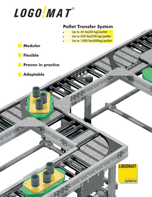
Modular<br />
Pallet Transfer System<br />
<br />
Up to 45 lbs(20 kg)/pallet<br />
Up to 550 lbs(250 kg)/pallet<br />
Up to 1300 lbs(600kg)/pallet<br />
Flexible<br />
Proven in practice<br />
Adaptable
Standard Width:<br />
5.<br />
9 in. - 19.7 in. (150 mm - 500 mm)<br />
Proven in practice at:<br />
ABB - BMW - Buderus - Daimler Chrysler - Danfoss - DT<br />
Industries - Ford - Getrag - Grob - Johnson Controls - LSW -<br />
Opel - Porsche - Thyssen Krupp - Visteon - Volvo - VW -<br />
Wabco - ZF<br />
02/04 subject to modifications<br />
2
Standard Width:<br />
5.<br />
9 in. - 19.7 in. (150 mm - 500 mm)<br />
The LOGO!<br />
MAT system adapts to all your<br />
needs with it’s precisely coordinated<br />
modules: from low cost to high-tech,<br />
everything is possible!<br />
02/04 subject to modifications<br />
3
XL-Version <strong>for</strong> Heavy Loads:<br />
Width 1.<br />
5 ft -2ft(500 mm - 600 mm)<br />
02/04 subject to modifications<br />
4
These images display examples of the<br />
LOGO!MAT Walk-on conveyors and<br />
demonstrate how space, normally enclosed<br />
by the track, becomes available <strong>for</strong><br />
additional accessibility to the workpiece.<br />
!<br />
LOGO MAT - Walk-on<br />
Tracks in Low Design<br />
R<br />
Discover the many applications of the<br />
LOGO!MAT conveyor system by following<br />
the 300 mm track throughout this brochure.<br />
02/04 subject to modifications<br />
5
LOGO!<br />
MAT - L Widths<br />
Max. Weight 550 lbs (250kg)/pallet<br />
StandardL<br />
Width mm in.<br />
150 5.91<br />
200 7.87<br />
250 9.84<br />
300 11.81<br />
400 15.75<br />
500 19.69<br />
Width=5.91 in.<br />
width<br />
L Rollers mm in.<br />
Diameter 50 1.97<br />
Spacing 57 2.24<br />
Width=7.87 in.<br />
width<br />
L Extrusion mm in.<br />
Depth 135 5.31<br />
Width=11.81 in.<br />
Width=9.84 in.<br />
width<br />
width<br />
Loaded pallet with<br />
wide mounting<br />
plate<br />
Load-capacity of the transfer system:<br />
max. 550 lbs per pallet!<br />
550 lbs<br />
Width=15.75 in.<br />
550 lbs<br />
width<br />
550 lbs<br />
Width=19.69 in.<br />
width<br />
02/04 subject to modifications<br />
6
LOGO!<br />
MAT - XL Widths<br />
Max. Weight 1300 lbs (600kg)/pallet<br />
XL-width=19.69 in.<br />
width<br />
StandardXL<br />
Width mm in.<br />
500 19.69<br />
600 23.62<br />
XL Rollers mm in.<br />
Diameter 60 2.36<br />
Spacing 68 2.68<br />
XL-width=23.62 in.<br />
width<br />
XL rollers are larger than the regular rollers.<br />
XL Extrusion mm in.<br />
Depth 213 8.39<br />
XL extrusions are larger than the regular extrusions allowing <strong>for</strong> extra support.<br />
The pallet weight limit is determined by the aluminium extrusions.<br />
Unloaded pallet with<br />
large, mounting plate<br />
Load capacity of the XL - transfer system:<br />
max. 1300 lbs per pallet!<br />
1300 lbs<br />
1300 lbs<br />
Heavy Weights<br />
The XL Version is made <strong>for</strong> workpieces<br />
weighting up to 1300 lbs!<br />
The XL tracks are available 19.69 in. and<br />
23.62 in. wide.<br />
02/04 subject to modifications<br />
7
Pallets<br />
The Pallet<br />
The pallet is designed specifically to suit the<br />
workpiece it is transporting. The pallet is<br />
comprised of two main parts:<br />
Short version<br />
1.) base<br />
2.) top plate<br />
Base Pallet<br />
The base pallet is made of high-quality,<br />
wear-resistant plastic. It comes in many<br />
different shapes and sizes appropriate to the<br />
specific application. For examle, the pallet<br />
base may have an opening in the middle to<br />
allow access (to the workpiece) from below.<br />
The base plate runs directly on the track and<br />
contains all the elements required <strong>for</strong><br />
transporting, stopping, presence-checking<br />
and tagging. The special design of the base<br />
pallet enables it to travel easily around<br />
corners and diverters.<br />
Long version<br />
Loaded pallet<br />
with small top<br />
plate<br />
Unloaded pallet<br />
with opening,<br />
without top<br />
mounting plate<br />
Pallet with opening<br />
Guide roller<br />
Stopper<br />
Metal strip <strong>for</strong> pallet<br />
presence check<br />
02/04 subject to modifications<br />
8
Specific pallets<br />
Top Plate or Mounting<br />
Plate<br />
Top mounting<br />
plate smaller<br />
than base pallet<br />
The dimensions of the top plate can be<br />
adapted to the workpiece. The top plate<br />
can be much longer and wider than the<br />
base, on which it is mounted. Upon<br />
request, the top plate can be made of<br />
various materials and include customized<br />
machining and tooling.<br />
Specific top plate<br />
Workpiece<br />
Top mounting<br />
plate larger<br />
than base pallet<br />
The workpiece to be transported can be<br />
placed either directly on the base pallet or<br />
on the pallet top (mounting) plate. Two or<br />
more pallets may be required depending<br />
on the dimensions of the workpiece.<br />
Samples of workpieces include but are not<br />
limited to: transmissions, engine blocks,<br />
and HVAC units.<br />
Specific top plate<br />
02/04 subject to modifications<br />
9
Advantages of the Roller<br />
Advantages of the Roller<br />
The tracks are generally equipped with<br />
friction rollers.<br />
Each roller has a built-in friction clutch.<br />
This lets the roller stand still under the<br />
stationary pallet during an acculumation of<br />
pallets. As a result, only very minimal <strong>for</strong>ce is<br />
generated. Also, the rollers do not cause<br />
additional wear to the base pallet.<br />
The rollers stand still under stationary pallet<br />
Pallet at stopper<br />
There are two kinds of rollers: full rollers and<br />
split rollers. Full rollers are most commonly<br />
used. Split rollers are intended <strong>for</strong><br />
workstations requiring access from below.<br />
Dirt particles, such as filings, simply fall<br />
between the rollers and do not hinder pallet<br />
transport.<br />
Roller stands still<br />
- No wear!<br />
Roller turns<br />
Setting screw <strong>for</strong> friction<br />
clutch<br />
The rollers in the track carry the weight of the<br />
pallet. The part of the roller touching the<br />
pallet stops when the pallet stops. The inside<br />
of the roller continues to move along with<br />
the chain.<br />
Built-in friction<br />
clutch<br />
The chain<br />
The chain acts as the driving element and<br />
does not carryout any transporting<br />
functions, consequently, prolonging the life<br />
of the chain. The entire chain is contained<br />
and protected in the side wall of the track.<br />
It is automatically tensioned at the chain<br />
drive.<br />
02/04 subject to modifications<br />
10
Freely Accessible Workpieces<br />
Simple roller replacement<br />
An opening in the base pallet and top plate<br />
creates access to the workpiece from below.<br />
Split rollers are installed in the track at the<br />
precise location where access is required. As<br />
a result, the underside of the pallet is easily<br />
accessible.<br />
Step<br />
1<br />
Open accessibility from below is helpful<br />
when:<br />
The workpiece is machined from below,<br />
through the pallet<br />
The pallet is positioned or rotated<br />
Forces or torques need to be applied, (i.e.<br />
at press fit stations, screw stations, ect.)<br />
Free accessibility<br />
from below<br />
Step<br />
2<br />
Free accessibility from below<br />
at any location<br />
Step<br />
3<br />
Split roller<br />
Full roller<br />
Split rollers are also used in the section <strong>for</strong><br />
indexing and stopping. They can be installed<br />
at any point on the track. Rollers can also<br />
be changed later within a few minutes.<br />
02/04 subject to modifications<br />
11
Turns<br />
Step<br />
1<br />
Step<br />
2<br />
Turns and junctions merely consist of<br />
straight track segments and curves<br />
Straight track<br />
segment<br />
Screw-mounted<br />
elements<br />
In the case of a corner turn, the pallets are<br />
guided steadily around the turn by specially<br />
designed plastic curves without the use of<br />
additional transfer units or pushers. This<br />
eliminates the additional costs of<br />
mechanical, pneumatic and special control<br />
equipment. The orientation of the pallet<br />
does not change in reference to the direction<br />
of travel - the front stays in the front. This<br />
simplifies design work <strong>for</strong> the planner<br />
and makes it possible to set up complete<br />
systems in less time. Subsequent expansions<br />
or changes in the system layout can be made<br />
quickly and inexpensively.<br />
In planning the system, only straight<br />
segments need to be combined to <strong>for</strong>m the<br />
overall layout. A turn consists of two straight<br />
track segments positioned at an angle of 90<br />
degrees. A pallet is deflected in the correct<br />
orientation by a curve that is simply inserted<br />
into the track.<br />
Just one curve, no<br />
moving parts, no complex<br />
controllers!<br />
Step<br />
3<br />
Turn<br />
02/04 subject to modifications<br />
12
Junctions and Diverters<br />
Diverter<br />
Pallets can move off or onto a particular<br />
path via junction elements. As <strong>for</strong> the<br />
turns, only straight track segments need to<br />
be combined to <strong>for</strong>m an overall layout. A<br />
junction consists of a pneumatically pivoted<br />
diverter arm that swings into the track and<br />
diverts a pallet onto another path. In this<br />
context, the orientation of the pallet does<br />
not change in reference to the direction of<br />
travel - the front stays in the front.<br />
Diverter, can be<br />
used at any<br />
location<br />
Junction, can be<br />
used at any<br />
location<br />
02/04 subject to modifications<br />
13
2 - Way Diverter<br />
2-way diverter<br />
Two-way diverters allow the pallet to change direction and make left<br />
or right turns. Pallets traveling from opposite directions on the same<br />
track can follow the same 2-way diverter into another track. The 2-<br />
way diverter slides into position and is electrically driven.<br />
2-way diverter<br />
Reversible track<br />
segment<br />
Reversible track<br />
segment<br />
The incoming or outgoing track requires a reversible drive unit to be<br />
able to change the direction of the track.<br />
Diverter<br />
Reversible<br />
drive unit<br />
2-way diverter<br />
02/04 subject to modifications<br />
14
Intersections<br />
A low-cost solution <strong>for</strong> intersections is<br />
achieved by the offset arrangement of a<br />
junction and a diverter.<br />
A rotating track segment offers more<br />
options <strong>for</strong> selecting the direction. This<br />
configuration even allows connection to<br />
tracks that branch off at an angle.<br />
Rotating<br />
module with<br />
track segment<br />
Intersection<br />
<strong>for</strong>med by<br />
offset tracks<br />
02/04 subject to modifications<br />
15
Changing the Pallet Orientation<br />
2-way diverter: pallet travels <strong>for</strong>ward into side<br />
track<br />
2-way diverter: diverter arm slides over<br />
2-way diverter: pallet travels backwards out of side<br />
track<br />
Step<br />
1<br />
Step<br />
2<br />
Step<br />
3<br />
The orientation of the pallet can be<br />
changed without using any complex rotating<br />
modules. The pallet simply travels <strong>for</strong>ward<br />
into the side track and then backs out,<br />
returning to the main track. Now the pallet is<br />
facing backwards, yet moving in the original<br />
track direction.<br />
Reversible side<br />
track segment<br />
Pallet has<br />
changed<br />
orientation<br />
Track extension<br />
Hinged, 2-way diverter<br />
Using a hinged 2-way diverter, the pallet can<br />
turn in a side track or travel straight through<br />
after the diverter arm swings away.<br />
At a corner, the pallet can be turned using a<br />
reversible track extension and a diverter.<br />
The pallet travels to the end of the track<br />
extension and is then guided “backwards”<br />
via the diverter onto the outgoing track.<br />
Reversible side<br />
track<br />
Hinged 2-way diverter: pallet travels straight<br />
ahead<br />
02/04 subject to modifications<br />
16
Arranging Off-Line Stations<br />
Off-line bypass<br />
Off-line stations can be set up at any<br />
location - even after the line is installed. The<br />
arrangement of the off-line bypass station<br />
provides additional buffer space that does<br />
not block the main line and can hold more<br />
than one pallet at a time.<br />
Another option <strong>for</strong> an off-line station is a<br />
small track section aligned parallel to the<br />
main line. A shuttle transports the pallet<br />
from the main line to the off-line track<br />
section and back. This parallel off-line<br />
station is ideal <strong>for</strong> small spaces and has a<br />
faster cycle time compared to the off-line<br />
bypass station.<br />
Off-line bypass<br />
station <strong>for</strong><br />
several pallets<br />
Parallel off-line<br />
station uses<br />
shuttle <strong>for</strong><br />
tranport pallet<br />
An off-line station can be<br />
set up at any location.<br />
Diverter<br />
Junction<br />
Shuttle<br />
Parallel off-line station uses shuttle to transport pallet<br />
02/04 subject to modification<br />
17
Arranging Off-Line Stations<br />
A side track with a diverter can be used to<br />
position a pallet with the front facing the<br />
machining station. For further transport,<br />
the pallet travels backwards onto a<br />
reversible track segment, into the main line<br />
and then <strong>for</strong>ward again to continue on.<br />
Pallet positioned with<br />
the front facing the<br />
machining station<br />
Side track<br />
Using a shuttle, a<br />
pallet can easily be<br />
transported to a<br />
parallel track line.<br />
Reversible track<br />
segment<br />
Reversible track<br />
segment<br />
02/04 subject to modifications<br />
18
Multiple Track Tiers<br />
Track lines can also be arranged in multiple<br />
tiers. For multiple tier systems the lifts can<br />
be driven electrically or pneumatically.<br />
Column arrangement: end<br />
Upper tier<br />
Lower tier<br />
02/04 subject to modifications<br />
19
Multiple Track Tiers<br />
Multiple track tiers are connected to one<br />
another by means of lifts. The lifts can be<br />
positioned at the end of, or within the line.<br />
The lifts can reach a height of over 16 ft<br />
(5000mm).<br />
Bridge<br />
Column<br />
Carriage with track segment<br />
Column arrangement:<br />
lateral<br />
Upper tier<br />
Lower tier<br />
02/04 subject to modifications<br />
20
Stopping Pallets<br />
Stopping<br />
Pallets are stopped when a stopper pin loc ks<br />
into position beneath the pallet. A stop<br />
locator in the base pallet prevents the pallet<br />
from bouncing back.<br />
Pallet in front of stopper<br />
Release<br />
Once the stopper pin retracts, the pallet<br />
immediately moves <strong>for</strong>ward and the stopper<br />
pin passes through a slot underneath the<br />
pallet. In this way, consecutive pallets can be<br />
released one at a time using a single stop<br />
unit.<br />
Location<br />
The stop unit can be installed and placed at<br />
any location on the track due to the T-slot in<br />
the aluminium frame. If the stop unit needs<br />
to be relocated, it can be done easily.<br />
Pallet stopped<br />
Additional Functions<br />
The stop unit may also have additional<br />
functions as it may have an optional<br />
presence-check sensor and a tag reader<br />
incorporated in it <strong>for</strong> specific applications.<br />
Different stop units are used depending on<br />
the pallet weight and the conveyor speed.<br />
Low back-up <strong>for</strong>ce<br />
thanks to friction clutch<br />
inside the rollers!<br />
Stopper, can be mounted at<br />
any location.<br />
Pallet released<br />
02/04 subject to modifications<br />
21
Short Cycle Times<br />
In order to achieve short cycle times at<br />
work stations, the pallet transfer times<br />
between the standby position and the<br />
machining position must be as short as<br />
possible.<br />
The use of shock absorbing stoppers<br />
allows higher conveyor speeds and<br />
shorter cycle times.<br />
In order to shorten the transfer times at<br />
specific stations, separately driven track<br />
segments with higher conveyor speeds<br />
can be installed in these areas. By means of<br />
a frequency controller, the pallets on these<br />
track segments are rapidly accelerated<br />
out of their standby position and then gently<br />
decelerated at the machining position,<br />
shortly be<strong>for</strong>e reaching the stopper.<br />
This technique ensures rapid and smooth<br />
pallet transfer.<br />
Shock-absorbing<br />
stopper<br />
Pallet in standby<br />
position<br />
Pallet in machining<br />
position<br />
Pallet in standby<br />
position<br />
Pallet in machining<br />
position<br />
High-speed track segment<br />
02/04 subject to modifications<br />
22
Workpiece Rotation<br />
An entire pallet can be lifted and rotated 90<br />
degrees in order <strong>for</strong> the workpiece to also be<br />
accessible from the front at an assembly<br />
station.<br />
Pallet designs are available with mounting<br />
plates that can rotate 90 degrees. The<br />
mounting plate is lifted off the base pallet<br />
and rotated pneumatically. The pallet can<br />
then continue on with the rotated mounting<br />
plate. The pallet is also positioned precisely<br />
during lifting and rotating.<br />
Lift-rotate unit<br />
Lift-rotate unit<br />
Pallet rotated 180<br />
degrees<br />
Mounting plate in<br />
longitudinal direction<br />
Mounting plate rotated<br />
90 degrees<br />
02/04 subject to modifications<br />
23
Pallet Positioning<br />
The pallet is first brought to a standstill <strong>for</strong><br />
the purpose of accurate positioning. By<br />
means of two contact points and two<br />
positioning pins, the entire pallet is then<br />
lifted from below to a point above the level of<br />
the rollers and precisely positioned in the x, y<br />
and z directions.<br />
The lift-locate unit with an integrated<br />
stopper can be installed at any location<br />
in the track. Different lift-locate units are<br />
used, depending on the size and weight of<br />
the pallet.<br />
Lift-locate unit extended<br />
Lift-locate unit can<br />
be installed at any<br />
location<br />
Preliminary<br />
stopper<br />
Lift-locate unit<br />
Integrated stopper<br />
Lift-locate unit with<br />
integrated stopper<br />
Lifting plate with positioning pins<br />
and contact points<br />
02/04 subject to modifications<br />
24
Accessories<br />
The LOGO!MAT system can be adapted to<br />
your requirements and factory specifications<br />
with various accessories.<br />
Clip-on side covers help to avoid dangerous,<br />
obstructing edges in areas near manual<br />
workstations. They also improve cleanliness<br />
and overall appearance.<br />
Clip-on cover <strong>for</strong> side walls<br />
Clip-on cover <strong>for</strong><br />
side walls<br />
Cover <strong>for</strong> spaces<br />
between rollers<br />
Drip pan<br />
Drip pan<br />
Drip pan to collect fluids.<br />
02/04 subject to modifications<br />
25
Modular System and Control Concept<br />
With the LOGO!MAT system, an entire<br />
assembly line can be designed and<br />
constructed in modular fashion. The<br />
costumized dimensions of the modules <strong>for</strong><br />
the individual stations or workplaces are<br />
defined in collaboration with the system<br />
planner.<br />
The modules are assembled to be entirely<br />
functional be<strong>for</strong>e delivery. Existing modules<br />
can be combined to create a complete<br />
system.<br />
They can be easily exchanged because all of<br />
the control and pneumatic equipment use<br />
plug-in connections between the individual<br />
modules.<br />
The control equipment is designed in<br />
accordance with your factory specifications.<br />
Module<br />
Module<br />
Module<br />
Module<br />
02/04 subject to modifications<br />
26
Walk-on<br />
Pallet Transfer System<br />
with Friction Rollers<br />
LOGO! MAT Walk-on<br />
Extremely<br />
flat design<br />
Walk-on system<br />
Modular concept<br />
Please request the<br />
Walk on catalog<br />
LOGO!<br />
MAT<br />
02/04 subject to modifications<br />
27
<strong>Logomat</strong> Automation Systems, Inc.<br />
2595 Arbor Tech Drive<br />
Hebron, Kentucky 41048<br />
Phone: 859-283-1759<br />
Fax: 859-283-1906<br />
www.logomat-online.com<br />
info@logomat-online.com