Heavy Commercial vehicle - Testers manual - Road Safety Authority
Heavy Commercial vehicle - Testers manual - Road Safety Authority
Heavy Commercial vehicle - Testers manual - Road Safety Authority

You also want an ePaper? Increase the reach of your titles
YUMPU automatically turns print PDFs into web optimized ePapers that Google loves.
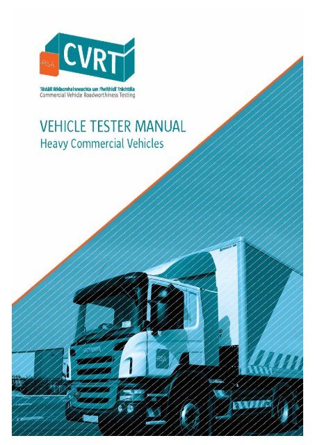
<strong>Road</strong> <strong>Safety</strong> <strong>Authority</strong><br />
<strong>Heavy</strong> <strong>Commercial</strong> Vehicle <strong>Testers</strong>’ Manual<br />
Applies to <strong>vehicle</strong> types;<br />
M2, M3, N2, N3, O3, O4 and<br />
Special Purpose M (Ambulance and Motor Caravan)<br />
These guidelines (also referred to as the “Manual”) are issued by the <strong>Road</strong> <strong>Safety</strong> <strong>Authority</strong> under section 38<br />
of the <strong>Road</strong> <strong>Safety</strong> <strong>Authority</strong> (<strong>Commercial</strong> Vehicle <strong>Road</strong>worthiness) Act 2012 (No. 16 of 2012). The intention<br />
behind this Manual is to set out requirements and guidance in relation to the carrying out of CVR tests at<br />
CVR testing centres.<br />
This Manual is to be complied with from the effective date advised by the RSA. CVR test operators and CVR<br />
testers shall ensure that CVR testing is carried out in accordance with this Manual from that date.<br />
This Manual sets out the testing methods to be employed by those involved in CVR testing. It also provides<br />
guidance to CVR test operators and CVR testers in relation to the reasons why a <strong>vehicle</strong> may fail a CVR test<br />
and the categorisation of defects identified in relation to a CVR <strong>vehicle</strong>.<br />
From the effective date, this Manual replaces the previous edition of the <strong>Road</strong>worthiness <strong>Testers</strong> Manual<br />
which, as of that date, is no longer in force.<br />
Owners of CVR <strong>vehicle</strong>s to which this Manual applies may also find the Manual useful in that it provides<br />
details of the inspections to which a CVR <strong>vehicle</strong> may be subjected and the reasons why it may not be<br />
issued with a pass statement following a CVR test.
REVISIONS<br />
This <strong>manual</strong> may be revised and updated from time to time. A current version is always available on the <strong>Road</strong> <strong>Safety</strong><br />
<strong>Authority</strong> website, www.cvrt.ie. If printing all or part of the <strong>manual</strong>, the website or CoVIS should always be checked to<br />
ensure any printed copy remains current.<br />
Version<br />
Date<br />
Section Number<br />
updated<br />
Description<br />
Page(s) Inserted by<br />
(responsible<br />
person);<br />
1.0 Sept 2013 All
CONTENTS<br />
The Testing Sequence<br />
Inspection Methodology<br />
and defect type by item<br />
Section<br />
Page<br />
Section<br />
Page<br />
Introduction 5<br />
Testing Sequence 9<br />
Inspection Methodology 14<br />
Registration/Trailer Plate and VIN 1 15<br />
Vehicle Weights and Dimensions Plate 2 18<br />
Pollution/Smoke 3 22<br />
Air/Vacuum Warning 4 25<br />
Air/Vacuum Build Up 5 26<br />
Horn 6 27<br />
Windscreen Wipers and Washers 7 28<br />
Mirrors 8 29<br />
Driver’s Seat 9 34<br />
<strong>Safety</strong> Belts 10 35<br />
Glass 11 38<br />
Mechanical Brake Hand Lever 12 43<br />
Service Brake Pedal 13 44<br />
Service Brake Operation 14 45<br />
Air/Vacuum Hand Control/Valves 15 47<br />
N/A 16 48<br />
Steering Wheel & Steering Play 17 49<br />
Warning Triangle 18 50<br />
Doors/Locks/Anti Theft Devices 19 52<br />
Electrical System 20 53<br />
Running Boards and Steps 21 54<br />
Cab and Bodywork 22 55<br />
N/A 23 —<br />
Tyre Condition 24 62<br />
Tyre Specification 25 63<br />
Tyre Tread 26 66<br />
Wheels 27 67<br />
Reflectors and Rear and Side Markings 28 68<br />
Malfunction Indicators 29 75<br />
Brake Fluid 30 76<br />
Side Guards and Rear Underrun Protection 31 77<br />
Spare Wheel and Carrier 32 84<br />
Reservoirs/Valves/Master Cylinders/Connections 33 85<br />
Fuel System 34 87<br />
Towing Coupling/Fifth Wheel 35 89<br />
Steering Alignment 36 93<br />
Service Brake Performance 37 94<br />
Service Brake Imbalance 38 96<br />
Emergency/secondary brake Performance 39 97<br />
Emergency/secondary brake Imbalance 40 99<br />
Parking Brake Performance 41 100<br />
Parking Brake Imbalance 42 101<br />
Steering Linkage 43 102<br />
Wheel Bearings 44 105<br />
Chassis Underbody 45 106<br />
Exhaust System/Noise 46 108<br />
Brake Wheel Units 47 109<br />
Mechanical Brake Components 48 110<br />
Brake Lines and Hoses 49 112<br />
Front Springs 50 114<br />
Front Suspension 51 117<br />
Shock Absorber Condition 52 119<br />
Transmission, Engine & Final Drive 53 120<br />
Rear Springs 54 122<br />
Rear Suspension 55 124<br />
Rear Lamps and Registration Plate Lamps 56 125<br />
Stop Lamps 57 126<br />
Indicators 58 127<br />
Side Lamps/Marker Lamp 59 128<br />
Headlamp Condition 60 129<br />
Headlamp Aim 61 130<br />
Fire Extinguishers (All Buses) 62 135<br />
Emergency Exits (All Buses) 63 136<br />
Passenger Seats (All Buses) 64 137<br />
Internal Lighting (All Buses) 65 138<br />
First Aid Kit (All Buses) 66 139<br />
Fuel Cut Off (All Buses) 67 140<br />
Spray Suppression 68 141<br />
Tachograph/Speedometer 69 146<br />
Speed Limiter 70 148<br />
Modifications Report 71 150
INTRODUCTION<br />
1. Definitions.<br />
“CVR” means <strong>Commercial</strong> Vehicle <strong>Road</strong>worthiness.<br />
“CVR Tester” means a person authorised by the <strong>Road</strong><br />
<strong>Safety</strong> <strong>Authority</strong> to be a CVR tester in respect of a<br />
particular category of <strong>vehicle</strong>s.<br />
“CVR Test Operator” means a person authorised by the<br />
<strong>Road</strong> <strong>Safety</strong> <strong>Authority</strong> to conduct CVR tests.<br />
“CVR Testing Centre” means a premises specified in a<br />
CVR test operator authorisation and complying with<br />
current Premises and Equipment Guidelines at which CVR<br />
tests may be carried out.<br />
“CRW” means a Certificate of <strong>Road</strong>worthiness.<br />
The term CVR Test means;<br />
an initial CVR test;<br />
a periodic CVR test;<br />
a partial CVR test;<br />
a re-test;<br />
An initial CVR test is the first roadworthiness test of a<br />
HCV and this test is due on the first anniversary of its<br />
registration. In the case of motor caravans, the initial CVR<br />
test is due on the fourth anniversary of its first registration.<br />
A periodic CVR test is a subsequent annual<br />
roadworthiness test of a HCV following its initial CVR test.<br />
An Enforcement Test (legally called a partial CVR test)<br />
is conducted when a <strong>vehicle</strong> is presented to a CVR<br />
Testing Centre on foot of a direction given by a RSA<br />
Authorised Officer or CVR Inspector. This test may include<br />
one or more test items and may include all test items<br />
applicable to that <strong>vehicle</strong>. Details of the test items to be<br />
tested will be available on CoVIS or listed on the copy of<br />
the <strong>Road</strong>side Check Inspection report as supplied to the<br />
driver of the <strong>vehicle</strong> and all items should be tested as per<br />
this <strong>manual</strong>. An Enforcement test may be conducted on<br />
any CVR Vehicle including <strong>vehicle</strong>s that are registered<br />
outside of the State.<br />
A re-test is a test carried out where a <strong>vehicle</strong> has failed an<br />
initial or periodic test, where:<br />
(a)<br />
(b)<br />
the re-test is carried out on a day which is not more<br />
than 21 calendar days after the day on which the<br />
<strong>vehicle</strong> has failed it’s initial or periodic test, and<br />
the reading on the <strong>vehicle</strong>'s odometer at presentation<br />
for the re-test is no more than 4,000 kilometres<br />
greater than the reading at the time the <strong>vehicle</strong> failed<br />
it’s initial or periodic test.<br />
A re-test can only be conducted at the CVR testing centre<br />
where the original test was failed.<br />
In carrying out a re-test on a <strong>vehicle</strong> only those items<br />
which gave rise to the refusal of the pass statement are<br />
to be tested.<br />
If during a retest the CVR tester notices any other<br />
obvious defects, then the owner shall be notified and<br />
these additional items must be tested. Where a<br />
reason for failure is issued with respect to these<br />
additional test items, then this will be recorded on the<br />
test report.<br />
Where a <strong>vehicle</strong> is refused a pass statement in<br />
relation to the brake performance/brake imbalance<br />
test or where it is failed on any brake components,<br />
then it must have a full brake test carried out on<br />
retest.<br />
A “voluntary safety CVR test” is a roadworthiness test,<br />
other than a CVR test, carried out in respect of one or<br />
more test items specified in this <strong>manual</strong>, which is<br />
recorded on CoVIS. As well as CVR <strong>vehicle</strong>s, a voluntary<br />
safety CVR test can also be carried out on <strong>vehicle</strong>s<br />
owned by the Gardaí or the Defence Forces.<br />
The term “owner” in the context of applying for a CVR<br />
test is taken to include the owner’s agent.<br />
“CoVIS” is the CVR computerised information system<br />
established by the <strong>Road</strong> <strong>Safety</strong> <strong>Authority</strong>. A CVR tester<br />
shall use CoVIS in order to process a CVR test on the<br />
lane equipment. CoVIS allows the tester to record defects<br />
and other standard inspection data such as mileage. The<br />
tester will also be able to record differences to Vehicle<br />
Details identified as part of the Test to the Vehicle Details<br />
on CoVIS that have come from the Driver and Vehicle<br />
Licensing Computer Services Division (DVCSD).<br />
“Method of Testing” details the ways in which the test<br />
of items on a <strong>vehicle</strong> are to be carried out and the<br />
equipment to be used. When carrying out each test,<br />
particular attention should be paid to the information<br />
given in the “Notes” since this gives guidance on the<br />
conduct and scope of the test.<br />
“Reasons for Failure” gives direction on the type of<br />
defects which will result in the <strong>vehicle</strong> failing. A <strong>vehicle</strong><br />
should only be assessed against the items and reasons<br />
for failure listed in this <strong>manual</strong>.<br />
An “Advisory Notice” is used to inform the customer of<br />
an item that should be rectified but does not prevent the<br />
<strong>vehicle</strong> from achieving a minimum standard of<br />
roadworthiness. This will be included on the Test Report<br />
or Pass Statement.<br />
"Semi-trailer" means the drawn component of an<br />
articulated <strong>vehicle</strong>, or a <strong>vehicle</strong> constructed or adapted for<br />
use as such drawn component.<br />
“Design Gross Vehicle Weight (DGVW)”, also known<br />
as the technically permissible maximum laden mass is the<br />
gross weight of a <strong>vehicle</strong> laden with the heaviest load<br />
which it can reasonably carry. This must take into<br />
consideration; the engine, brakes, tyres and general<br />
construction of such <strong>vehicle</strong> and shall, until the contrary is<br />
shown, be taken to be its design gross weight as<br />
specified by its manufacturer or an automotive engineer.<br />
HCV TESTERS MANUAL V 1.0 Page | 5
“Gross Combination Weight”, (GCW) (also known as<br />
the technically permissible maximum mass of the<br />
combination) is the maximum mass allocated to the<br />
combination of a motor <strong>vehicle</strong> and one or more trailers on<br />
the basis of its construction features and its design<br />
performances or the maximum mass allocated to the<br />
combination of a <strong>vehicle</strong> and trailer.<br />
“Individual design axle weight” means the mass<br />
corresponding to the maximum permissible static vertical<br />
load transmitted to the ground by the wheels of the axle,<br />
on the basis of the construction features of the axle and of<br />
the <strong>vehicle</strong> and their design performances.<br />
“Manufacturer's plate” means a plate or label, affixed by<br />
the manufacturer on a <strong>vehicle</strong> that provide the main<br />
technical characteristics which are necessary for the<br />
identification of the <strong>vehicle</strong> and provides the competent<br />
authorities with the relevant information concerning the<br />
technically permissible maximum laden masses;<br />
“First registered”’ means the date when the <strong>vehicle</strong> was<br />
first registered with the Revenue Commissioners or the<br />
date when first registered in accordance with the laws of<br />
another country.<br />
“First licensed” means the date a semi-trailer or trailer is<br />
first licensed with the Local <strong>Authority</strong> in whose functional<br />
area it is normally kept, irrespective of the original date of<br />
manufacture and irrespective of whether or not the semitrailer<br />
was previously registered/licensed in another<br />
country.<br />
"Appropriate motor <strong>vehicle</strong>" means a mechanically<br />
propelled <strong>vehicle</strong> having at least three axles, twin tyres, air<br />
suspension or an equivalent suspension on each driving<br />
axle and ABS brakes. The <strong>vehicle</strong> must also be fitted with<br />
a plate complying with the requirements of the Regulations<br />
of 2000.<br />
"Appropriate semi-trailer" means a semi-trailer which<br />
has an air suspension or an equivalent suspension and<br />
ABS brakes. It must also be fitted with a plate complying<br />
with the requirements of the Regulations of 2000.<br />
The ‘appropriate semi-trailer’ concept came into force<br />
on 1 st April 2013 and applies to all semi-trailers<br />
(irrespective of when they were first licensed) operating<br />
as part of a combination of <strong>vehicle</strong>s with a gross weight<br />
in excess of 40 tonnes.<br />
“Insecure”<br />
The term “insecure” is used throughout this Manual to<br />
describe a defective condition. The term should be<br />
taken by testers to mean the following:<br />
(a) that a component on the <strong>vehicle</strong> has relative<br />
movement either at its fixing or in relation to an<br />
associated component where there should be none<br />
or<br />
(b) that a component is not safely or completely<br />
attached either at its fixing or to an associated<br />
component.<br />
“Worn”<br />
A component will be considered worn where the wear is<br />
to such an extent that it is either;<br />
HCV TESTERS MANUAL V 1.0 Page | 6<br />
(a) likely to fail, or<br />
(b) clearly not functioning effectively as designed, or<br />
(c) visibly worn beyond manufacturers known permitted<br />
limits, or<br />
(d) likely to affect the operation or condition of another<br />
safety related component.<br />
2. Scope.<br />
This Manual applies to the following categories of<br />
<strong>vehicle</strong>s;<br />
<br />
<br />
<br />
Category M2: Vehicles designed and constructed for<br />
the carriage of passengers, comprising more than<br />
eight seats in addition to the driver’s seat, and having a<br />
DGVW not exceeding 5 tonnes.<br />
Category M3: Vehicles designed and constructed for<br />
the carriage of passengers, comprising more than<br />
eight seats in addition to the driver’s seat, and having a<br />
DGVW exceeding 5 tonnes.<br />
Category N2: Vehicles designed and constructed<br />
primarily for the carriage of goods and having a DGVW<br />
exceeding 3.5 tonnes but not exceeding 12 tonnes.<br />
Category N3: Vehicles designed and constructed<br />
primarily for the carriage of goods and having a DGVW<br />
exceeding 12 tonnes.<br />
Category O3: Trailers with a DGVW exceeding 3.5<br />
tonnes but not exceeding 10 tonnes.<br />
Category O4: Trailers with a DGVW exceeding 10<br />
tonnes.<br />
Ambulances (special purpose <strong>vehicle</strong>s in category M).<br />
<br />
Motor caravans with a DGVW exceeding 3.5 tonnes<br />
(special purpose <strong>vehicle</strong>s in category M).<br />
3. Making a request for a CVR Test Booking.<br />
A request for a CVR test booking must be made to a CVR<br />
test operator in person, or by using CoVIS. An application<br />
for a booking to a CVR test operator may be made at the<br />
test centre before the test commences. Full details of how<br />
to make a request for a test booking can be found at<br />
www.cvrt.ie.<br />
4. Presentation of ID.<br />
A person who presents a <strong>vehicle</strong> or a trailer to be tested is<br />
required to produce a valid identification e.g. a driving<br />
licence or passport. Where a valid identification is not<br />
presented at the time of the test, the CVR test may be<br />
carried out but a pass statement will not be issued. The<br />
CVR test operator may issue a pass statement in respect<br />
of the <strong>vehicle</strong> where the person who presented the <strong>vehicle</strong><br />
provides the required identification subsequently and this<br />
should be presented within 21 calendar days from the date<br />
of the CVR test.<br />
5. CoVIS, Test Reports and Pass Statements.<br />
The CVR tester must complete a checklist printed from<br />
CoVIS for each test conducted confirming that all required<br />
test items have been tested and these must be recorded<br />
on CoVIS. Once a CVR test has been completed, the CVR<br />
tester must complete a declaration that he or she has<br />
completed the test correctly. A test report is issued by the<br />
CVR tester to the owner giving details of the captured<br />
equipment results and any failed visual items. Where the<br />
CVR tester is satisfied that the <strong>vehicle</strong> has passed all the<br />
required test items specified in this <strong>manual</strong>, then a pass
statement is issued (apart from point 4 above). Where a<br />
pass statement is not issued, the reasons for refusal will be<br />
provided to the owner in the test report. In the case of a<br />
voluntary safety test, a test report will be provided but no<br />
pass statement will be issued. If a CVR test is not<br />
completed, then the test report issued will contain the<br />
words “Not complete”.<br />
Where the test lane equipment is not automatically linked<br />
to CoVIS, the CVR Tester will have to <strong>manual</strong>ly input the<br />
test results on CoVIS. The paperwork associated with<br />
these tests shall be retained by the CVR Test Operator.<br />
Any supplementary documentation required as part of the<br />
test (such as modification reports, safety belt<br />
documentation, tachograph declaration) shall be scanned<br />
and uploaded onto the CoVIS system.<br />
If either the scanner or CoVIS are not operational, the<br />
documents shall be retained by the test operator.<br />
Figure 1.“Fail Dangerous” Notice: Windscreen Front<br />
If the CVR Tester needs to stop in the middle of the test<br />
they will be able to save results up to that point and<br />
resume testing later that day. Only the tester who<br />
commenced the test may resume the test. Where a tester<br />
has started a test and is not available to complete it for<br />
whatever reason, the test must be abandoned and it must<br />
be started again on the <strong>vehicle</strong> by another tester, from the<br />
beginning.<br />
6. Assessment of Defects.<br />
In line with Commission Recommendation 2010/378/EU,<br />
this test <strong>manual</strong> categorises the seriousness of failure for<br />
each defect into the following;<br />
Minor Defects (MiD)<br />
Technical defects that have no significant effect<br />
on the safety of the <strong>vehicle</strong> and other minor noncompliances.<br />
Major Defects (MaD)<br />
Defects that may prejudice the safety of the<br />
<strong>vehicle</strong> or put other road users at risk and other<br />
more significant non- compliances.<br />
Dangerous Defects (DD)<br />
Defects that constitute a direct and immediate<br />
risk to road safety such that the <strong>vehicle</strong> should<br />
not be used on the road under any<br />
circumstances.<br />
For defects which can be classified in more than one<br />
category, the tester shall use his experience and technical<br />
expertise to categorise the particular defect in the<br />
appropriate defect category.<br />
On completion of a CVR test, voluntary safety test or a<br />
enforcement test, and where a <strong>vehicle</strong> is failed because<br />
of a Dangerous Defect, the CVR tester shall affix a “Fail<br />
Dangerous” notice to the <strong>vehicle</strong>. For <strong>vehicle</strong>s with a<br />
windscreen, a double-sided “Fail Dangerous” notice shall<br />
be affixed on the passenger side of the windscreen so as<br />
not to impair the vision of the driver. The template that<br />
this double sided notice shall take is set out in Figures 1<br />
and 2 that follow. In the case of trailers, a “Fail<br />
Dangerous” notice as set out in Figure 3 shall be affixed<br />
to an area of the <strong>vehicle</strong> which is clearly visible and<br />
readily accessible for inspection.<br />
Figure 2.“Fail Dangerous” Notice: Windscreen Back<br />
Figure 3.“Fail Dangerous” Notice: Trailer<br />
7. Restriction on CVR <strong>Testers</strong> carrying out<br />
certain tests.<br />
During a CVR test, a CVR tester shall not carry out any<br />
repairs on the <strong>vehicle</strong> other than an adjustment of<br />
headlight focus to the required standard. Where this<br />
adjustment is made, it must be noted on CoVIS. Where<br />
the <strong>vehicle</strong> fails on other items, the test must be<br />
completed and a test report issued. It shall be possible for<br />
a <strong>vehicle</strong> to be tested and retested on the same day.<br />
A CVR tester shall not carry out a test on a <strong>vehicle</strong> which<br />
he/she has carried out any repairs or maintenance work<br />
on in the 2 days previous.<br />
A CVR tester shall not carry out a CVR test on a <strong>vehicle</strong><br />
where that CVR tester has a legal or beneficial interest in<br />
the <strong>vehicle</strong>, unless details of the proposed test have been<br />
given to the <strong>Road</strong> <strong>Safety</strong> <strong>Authority</strong> at least 2 working days<br />
in advance.<br />
HCV TESTERS MANUAL V 1.0 Page | 7
A CVR tester can only carry out tests on the categories of<br />
<strong>vehicle</strong>s to which he or she is authorised.<br />
8. Reasons to Refuse to Carry Out a CVR Test.<br />
A CVR tester may refuse to carry out a CVR test if<br />
(a) in his or her opinion<br />
(i) any part of the <strong>vehicle</strong> or any of its equipment is in<br />
such a condition that it would not be safe or<br />
practicable to carry out the CVR test or<br />
(ii) a load on the <strong>vehicle</strong> is in such condition or is not<br />
adequately secured that it would be safe or<br />
practicable to carry out the CVR test.<br />
or<br />
(b) fee payable in respect of the CVR test has not been<br />
paid.<br />
The equipment to be used for the purposes of carrying<br />
out CVR tests are those specified in The Premises and<br />
Equipment Guidelines 2013 issued by the <strong>Road</strong> <strong>Safety</strong><br />
<strong>Authority</strong>. Where specific equipment is designated for a<br />
particular test, only this equipment shall be used for the<br />
test. Where the brakes cannot be tested on a roller brake<br />
tester due to the design of the <strong>vehicle</strong>, a road test must<br />
be carried out using a decelerometer to evaluate the<br />
brake performance.<br />
The specialised equipment used for the test should only<br />
be used by trained and experienced personnel. CVR<br />
testers should be thoroughly familiar with the<br />
manufacturer’s detailed operating instructions and the<br />
procedures which must be followed to ensure the safe<br />
operation of this specialised equipment.<br />
9. Postponing the issue of a CRW.<br />
Where a pass statement is issued by a CVR test<br />
operator, the CVR tester shall verify with the presenter<br />
that the details of the registered owner on the pass<br />
statement are correct. Where the details differ, the<br />
presenter may request that the issuing of the CRW be<br />
postponed for a period of up to 14 days. The CVR tester<br />
shall advise the presenter to contact the DVCSD in order<br />
to have the ownership details updated as soon as<br />
possible. The presenter/owner should be advised that the<br />
CRW will issue after 14 days to the registered owner on<br />
the National Vehicle Driver File.<br />
prediction of future <strong>vehicle</strong> roadworthiness.<br />
Because it is not practicable to lay down limits of wear and<br />
tolerance for all types of components of different models of<br />
<strong>vehicle</strong>, CVR testers are expected to use their experience<br />
and judgment in making an assessment of the condition of<br />
components, i.e. is replacement, repair, adjustment or<br />
certification necessary Where the <strong>vehicle</strong> or trailer<br />
manufacturer has provided wear tolerances these should<br />
be adhered to.<br />
The Methods of Testing detailed in this Manual are<br />
designed to comply with normal workshop practice. The<br />
<strong>Road</strong> <strong>Safety</strong> <strong>Authority</strong> cannot accept responsibility for any<br />
injury to any person or any damage to any property arising<br />
from the conduct of any test described in this Manual.<br />
Nothing in this Manual may be construed as diminishing in<br />
any way the obligations on employers from health and<br />
safety regulatory acts in relation to the occupational health<br />
and safety at work of their employees.<br />
It is the responsibility of the person presenting the <strong>vehicle</strong><br />
for test to prove exemption from any requirement listed in<br />
this <strong>manual</strong>.<br />
The testing sequence.<br />
Pages 9, 10, 11 and 12 illustrate in general terms the<br />
sequence of tests to be carried out. Page 10 is mainly<br />
involved with tests which may be carried out on hard<br />
standing and Page 11 is mainly involved with tests carried<br />
out from underneath the <strong>vehicle</strong>. It is essential that<br />
headlamp checks be carried out with the <strong>vehicle</strong> in the<br />
certified area only. Class V and Class VI mirrors must be<br />
checked in the dedicated area. Checks on such items as<br />
steering play, linkage wear, leaks or play in braking<br />
systems, suspension wear, smoke emission and brake<br />
lights will normally require a two person team working<br />
together. The test sequence will of course vary with<br />
different <strong>vehicle</strong> types.<br />
10. Odometer.<br />
The CVR tester must record the odometer reading at<br />
the time of the test where an odometer is fitted. When<br />
the test report or pass statement is being presented to<br />
the owner or the presenter of the <strong>vehicle</strong>, the CVR<br />
tester shall point out the odometer reading. The owner<br />
or the presenter of the <strong>vehicle</strong> shall be asked to<br />
confirm that the entry of the odometer reading is<br />
correct, and if not shall immediately advise the CVR<br />
Tester.<br />
11. General.<br />
The test is essentially a maintenance and condition<br />
check. A detailed assessment of a <strong>vehicle</strong>’s design and<br />
constructionisnotpartofthetest.Itshouldalsobenoted<br />
that the test can only confirm the roadworthiness<br />
condition of the <strong>vehicle</strong> at the time of the test. It is not a<br />
HCV TESTERS MANUAL V 1.0 Page | 8
TEST PROCEDURE TO BE FOLLOWED<br />
Brake Test and lights may be changed around depending on equipment layout<br />
IN CAB AROUND VEHICLE BRAKE TEST UNDERBODY LIGHTS<br />
Chassis/No.Plate (1)<br />
Weights & Dimensions Plate (2)<br />
Dash/Malfunction Indicators/<br />
main beam light (20, 14, 60)<br />
Indicator Tell Tales (58)<br />
Battery Light (20)<br />
Oil Warning Light (3)<br />
Smoke test (3)<br />
Brake Gauges/Buzzer (4)<br />
Air/Vac Build up time (5)<br />
Horn (6)<br />
Wipers/Washers (7)<br />
Mirrors (8)<br />
Driver’s Seat (9)<br />
Seat Belts (10)<br />
Glass/Window Winder (11)<br />
Brake Controls (12, 13, 14, 15)<br />
Tachograph/Speedometer (69)<br />
Speedlimiter (70)<br />
Steering Play (17)<br />
Warning Triangle (18)<br />
Door/Locks/Anti Theft<br />
Devices (19)<br />
Electrical System (20)<br />
Transmission (53)<br />
Cab Condition (22)<br />
Running Board Steps (21)<br />
R/H Door (19)<br />
Demister [Bus] (22)<br />
First Aid Kit [Bus] (66)<br />
Fire extinguisher [Bus] (62)<br />
Seat Belts (10)<br />
R/H Step (22)<br />
R/H Front Mudguard (22)<br />
R/H Front Tyre (24, 25, 26)<br />
R/H Front Wheel (27)<br />
Side Marking (28)<br />
Front No. Plate (1)<br />
Windscreen Markings (11)<br />
Wipers (7)<br />
Brake Fluid (30) Clutch Fluid<br />
(53)<br />
Power Steering Fluid (43)<br />
Steering Column (17)<br />
Bumper Bar (22)<br />
L/H Door/Locks (19)<br />
L/H Step (21)<br />
Cab Mounting (22)<br />
L/H Front Mudguard (22)<br />
L/H Front Tyre (24, 25, 26)<br />
L/H Front Wheel (27)<br />
Body Condition (22)<br />
Brake Reservoirs (33)<br />
Side Marking (28)<br />
Side Guards (31)<br />
L/H Rear Mudguard (22)<br />
L/H Rear Tyre (24, 25, 26)<br />
L/H Rear Wheel (27)<br />
Electrical System (20)<br />
Body Condition (22)<br />
Rear Underrun Guard (31)<br />
Towing Coupling (35)<br />
Electrical System (20)<br />
Body Condition (22)<br />
Spare Wheel Carrier (32)<br />
Rear No. Plate (1)<br />
Brake Connections (49)<br />
Suzie pressure (49)<br />
Rear Markings (28)<br />
R/H Rear Tyre (24, 25, 26)<br />
R/H Rear Wheel (27)<br />
R/H Rear Mudguard (22)<br />
Body Condition (22)<br />
Side Markings (28)<br />
Side Guards (31)<br />
Air/Vac Tanks (33)<br />
Electrical System (20)<br />
Fuel Tank (34)<br />
Brake Fluid (30)<br />
Brake Reservoirs (33)<br />
Tipping Gear (22)<br />
Fuel Cut Off [Bus] (67)<br />
Emergency Exit [Bus] (63)<br />
Steering Alignment (36)<br />
Service Brake<br />
Performance (37)<br />
Service Brake<br />
Imbalance (38)<br />
Secondary Brake<br />
Performance (39)<br />
Secondary Brake<br />
Imbalance (40)<br />
Parking Brake<br />
Performance (41)<br />
Parking Brake<br />
Imbalance (42)<br />
Steering Linkage (43)<br />
Wheel Bearings (44)<br />
Chassis/Cross Members (45)<br />
Electrical System (20)<br />
Exhaust System (46)<br />
Front Axle Brake<br />
Wheel Units (47)<br />
Front Axle Brake<br />
Components (48)<br />
Brake Pipes (49)<br />
Front Axle Springs (50)<br />
Front Axle Shock<br />
Absorbers (52)<br />
Front Axle Beam (51)<br />
Front Axle Suspension (51)<br />
Front Axle Tyres (24, 25, 26)<br />
Oil Leaks (53)<br />
Engine Mountings (53)<br />
Gearbox Mountings (53)<br />
Drivetrain (53)<br />
Tachograph Seals (69)<br />
Chassis /Cross members (45)<br />
Fuel System (34)<br />
Exhaust System (46)<br />
Drive Shaft[s] (53)<br />
Silencer Box (46)<br />
Body Clamps (22)<br />
Brake Valves (33)<br />
Brake Pipes (49)<br />
Electrical Wiring (20)<br />
Brake Air/Vac Tanks ( 33)<br />
Mechanical Brake<br />
Components (48)<br />
Chassis/Cross Members (45)<br />
Drive Shaft[s] (53)<br />
Rear Axle (55)<br />
Rear Axle Brake<br />
Wheel Units (47)<br />
Rear Axle Brake<br />
Components (48)<br />
Brake Pipes (49)<br />
Rear Axle Springs (54)<br />
Rear Axle Shock<br />
Absorbers (52)<br />
Rear Suspension (55)<br />
Rear Axle Tyres (24, 25, 26)<br />
Electrical Wiring (20)<br />
Chassis/Cross<br />
members (45, 22)<br />
Towing Coupling (35)<br />
Headlamp<br />
Condition (60)<br />
Headlamp Aim<br />
(61)<br />
Headlamp Main<br />
Beam (60)<br />
Side Lights (59)<br />
Front<br />
Indicators/<br />
Repeaters (58)<br />
Rear Lights<br />
(56)<br />
No. Plate Lamp<br />
(56)<br />
Stop Lamps<br />
(57)<br />
Indicators Rear<br />
(58)<br />
Rear Reflectors<br />
(28)<br />
Side Reflectors<br />
(28)<br />
Long Vehicle<br />
Sign (28)<br />
HCV TESTERS MANUAL V 1.0 Page | 9
TEST PROCEDURE TO BE FOLLOWED<br />
HCV TESTERS MANUAL V 1.0 Page | 10
PROCEDURE FOR UNDERBODY INSPECTION<br />
Electrical<br />
Air/Vac Tanks<br />
HCV TESTERS MANUAL V 1.0 Page | 11
VEHICLE ON CERTIFIED AREA FOR TESTING HEADLAMP AIM<br />
NOTE: Floor Area to be within ± 1mm of a chosen Reference Point for a distance of 10 metres before<br />
the beamsetter. Rails to be within ± 0.5mm of a chosen Reference Point.<br />
HCV TESTERS MANUAL V 1.0 Page | 12
ADDITIONAL ITEMS TO BE CHECKED ON A BUS<br />
ADDITIONAL ITEMS TO BE CHECKED ON A SEMI-TRAILER<br />
HCV TESTERS MANUAL V 1.0 Page | 13
TESTING METHODOLOGY AND<br />
DEFECT TYPE BY ITEM<br />
NOTE: <strong>Testers</strong> should not start a test in any of the following circumstances:<br />
(i)<br />
(ii)<br />
where in their opinion any part of the <strong>vehicle</strong> or any of its equipment is in such a dirty or dangerous<br />
condition as to make it unreasonably difficult to carry out the test.<br />
where the load or other items are not adequately secured.<br />
(iii) If any relevant test equipment is missing, not working, or out of calibration.<br />
The <strong>vehicle</strong> should be logged in the system as a Fail due to conditions (i) or (ii) above.<br />
HCV TESTERS MANUAL V 1.0 Page | 14
1<br />
1<br />
REGISTRATION/TRAILER PLATE AND VIN<br />
Method of Testing<br />
1. Check the registration number plates or trailer mark plate for security, location, format, legibility and that the numbers<br />
are the same as that on CoVIS. No other marks may appear on the plate. Any additional tabs, etc. outside the<br />
dimensions shown for the registration plate are not considered part of the plate.<br />
2. Check that the VIN is indelibly marked on the chassis and corresponds to the number on CoVIS for this <strong>vehicle</strong><br />
3. Check in the case of a trailer that the trailer mark is indelibly marked on the offside chassis rail and are of the<br />
correct dimensions.<br />
4. Check that the <strong>vehicle</strong> meets with the description assigned to it on CoVIS.<br />
5. Check that the <strong>vehicle</strong> meets with the EU Category assigned to it on CoVIS.<br />
NOTES<br />
Owners of <strong>vehicle</strong>s registered prior to 31 st December, 1990, have the option of converting their registration<br />
plates to the new format<br />
(1) Vehicles Registered on or after 1 st January 1991<br />
For <strong>vehicle</strong>s registered on or after 1 st January, 1991, registration plate letters and numbers must be black,<br />
set against a white background of reflex reflective material. The flag of the European Union, the Nationality<br />
Symbol IRL and the Irish language name of the City/County of registration to be shown.<br />
(2) Vehicles Registered on or after 1 st January 1987<br />
For <strong>vehicle</strong>s registered on or after 1 st January, 1987, registration plate letters and numbers must be black,<br />
set against a white background of reflex reflective material and minimum dimensions should be as shown<br />
in the sketches on page 16.<br />
(3) Vehicles registered prior to 1 st January 1987<br />
Reflex Reflecting Registration Plates<br />
(a) Reflex Reflecting<br />
Front registration plates should have black numbers and letters on a white background. Rear<br />
registration plates should have black numbers and letters on a red or white background.<br />
(b) Non-Reflex Reflecting<br />
Front and rear registration plates should have white, silver or light grey numbers and letters on a<br />
black background.<br />
(c) Back Lit Registration Numbers and Letters<br />
Where registration numbers and letters are back lit they should appear white in front and either white<br />
or red to the rear during lighting up hours. At all other times they should appear white on a black<br />
background.<br />
(4) Dimensions should be as shown in the illustration on page 16.<br />
(5) Where the indented space provided for the number plate is not sufficient to accommodate a<br />
standard size number plate, the registration plate and registration letters and numbers may be<br />
reduced in size relative to the space provided for the number plate.<br />
(6) Trailer Registration Number Plate<br />
The trailer registration number plate should consist of black numbers and letters 76mm (3”) high on<br />
a white background and should be fitted to the nearside chassis rail.<br />
The trailer registration letters and numbers must also be clearly and indelibly marked with characters<br />
at least 30mm high on the offside chassis rail.<br />
(7) Where a new VIN plate has been fitted, then the original VIN plate shall be retained alongside the new<br />
VIN plate.<br />
HCV TESTERS MANUAL V 1.0 Page | 15
1<br />
REGISTRATION PLATE AND VIN (CHASSIS NUMBER) Cont..<br />
DIMENSIONS FOR NUMBER PLATES<br />
All dimensions in millimetres<br />
HCV TESTERS MANUAL V 1.0 Page | 16
1<br />
REGISTRATION/TRAILER PLATE AND VIN<br />
ITEM REASONS FOR FAILURE MiD MaD DD<br />
01 Registration Number Plate<br />
(see page 16) or trailer<br />
registration number plate.<br />
(1) One or both plates missing or insecure. X<br />
(2) Numbers or letters missing or illegible or wrong size (see page<br />
16).<br />
X<br />
X<br />
(3) Numbers, letters or background of incorrect colour (see notes on<br />
page 15).<br />
X<br />
(4) Registration number does not correspond with that stated on<br />
CoVIS.<br />
(5) In the case of trailers and semi-trailers the trailer registration<br />
number plate is not fitted to the near side chassis rail.<br />
X<br />
X<br />
(6) The trailer registration number is not indelibly marked on the<br />
offside chassis rail with characters of minimum 30mm height in an<br />
accessible position.<br />
X<br />
(7) Other letters, numbers, or marks are on the registration number<br />
plate.<br />
X<br />
02 VIN (1) VIN not available or does not correspond with the number stated<br />
on CoVIS.<br />
X<br />
(2) VIN is missing or not legible on chassis. X<br />
03 EU category (where stated<br />
on CoVIS)<br />
(1) EU category for the vehcile presented does not correspond with<br />
the EU category stated on CoVIS.<br />
X<br />
ADVISORY NOTICE<br />
Where the <strong>vehicle</strong> does not match description on CoVIS.<br />
Where the EU category for the <strong>vehicle</strong> does not correspond with the EU category stated on CoVIS.<br />
HCV TESTERS MANUAL V 1.0 Page | 17
2<br />
VEHICLE WEIGHTS AND DIMENSIONS PLATE<br />
Method of Testing<br />
1. Check in the case of a <strong>vehicle</strong>, trailer or semi-trailer with a design G.V.W. exceeding 3,500kg that a metal plate<br />
similar to that shown on pages 19 and 20 is securely fitted to the <strong>vehicle</strong>.<br />
2. Check in the case of a passenger <strong>vehicle</strong> with a design G.V.W. exceeding 5,000kg that a metal plate similar to that<br />
shown on page 19 is securely fitted to the <strong>vehicle</strong>.<br />
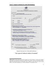
3. Check that in the case of a plate fitted by an Authorised Plate Fitter that the plate seal is intact.<br />
4. Check that the plate shows all the required details (see plate on pages 19 and 20).<br />
5. A 3-axle tractor unit plated for 44 tonnes GCW is required to have an anti-lock braking system and an air<br />
suspension system (or equivalent) as per the definition of “appropriate motor <strong>vehicle</strong>” (please see Note 1of<br />
Introduction for definition).<br />
6. A 3-axle tractor unit plated for 46 tonnes GCW first registered prior to 1 st April 2013 (in addition to satisfying the<br />
definition of an “appropriate motor <strong>vehicle</strong>” as outlined in Note 1 of the Introduction) is required to have an Electronic<br />
Braking System (EBS) 1 .<br />
7. A 3-axle tractor unit plated for 46 tonnes GCW first registered on or after 1 st April 2013 (in addition to satisfying the<br />
definition of an “appropriate motor <strong>vehicle</strong>” as outlined in Note 1 of the Introduction) is required to have an Electronic<br />
Braking System (EBS) & be fitted with a Vehicle Stability Function (VSF) 2 , which is more commonly known as<br />
Electronic Stability Control (ESC).<br />
Motor-caravans and passenger <strong>vehicle</strong>s with a DGVW up to 5,000kg<br />
8. Examine alterations made to the manufacturers plate. In cases where the details contained on the original<br />
manufacturers plate have been altered, then this alteration must be justified, approved and documented by the<br />
manufacturer or his authorised distributor. In the absence of a manufacturers report, then a modifications report in<br />
the format prescribed in Section 71 of this test <strong>manual</strong> must be provided.<br />
NOTES<br />
(1) The only plates acceptable are those fitted by the <strong>vehicle</strong>/trailer manufacturer or an Authorised Person<br />
appointed by NSAI.<br />
(2) A single plate affixed by the <strong>vehicle</strong> manufacturer which contains all of the required information as<br />
detailed on pages and 19 and 20 respectively is sufficient.<br />
(3) Where a <strong>vehicle</strong> or trailer has been plated by the manufacturer a combination of two plates is acceptable.<br />
(4) Plates fitted by an Authorised Person will bear a number issued to that person by NSAI. Vehicle<br />
Identification Number (VIN) is the manufacturer’s unique <strong>vehicle</strong> identification number, also known as the<br />
chassis number.<br />
1 “electronic braking system” means a braking system that employs an electronic control system to control the<br />
braking function.<br />
2 ‘<strong>vehicle</strong> stability function’ (more commonly known as Electronic Stability Control) means an electronic control<br />
function for a <strong>vehicle</strong> which improves the dynamic stability of the <strong>vehicle</strong>. A <strong>vehicle</strong> stability function includes<br />
one or both of the following: (a) Directional control & (b) Roll-over control.<br />
HCV TESTERS MANUAL V 1.0 Page | 18
2<br />
WEIGHTS AND DIMENSIONS PLATE<br />
(MECHANICALLY PROPELLED VEHICLE)<br />
(All inscriptions 4mm in height)<br />
Name of Manufacturer:<br />
Type Approval Number:<br />
Vehicle Identification Number:<br />
Maximum permitted laden weight<br />
Maximum permitted laden weight<br />
of combination (if permitted to<br />
tow a trailer)<br />
Weights Not to be<br />
Exceeded in<br />
Ireland<br />
Maximum Weights<br />
Permitted under<br />
EU Directives<br />
Design Weights<br />
(if higher than<br />
permitted in Ireland)<br />
Axle 1<br />
Axle 2<br />
Axle weights<br />
Axle 3<br />
Axle 4<br />
Vehicle Length L =<br />
Vehicle Width W =<br />
Data relating to Length of<br />
Combinations<br />
Centre of coupling to front of<br />
<strong>vehicle</strong> (a)<br />
amax =<br />
amin =<br />
HCV TESTERS MANUAL V 1.0 Page | 19
2<br />
WEIGHTS AND DIMENSIONS PLATE<br />
(TRAILER AND SEMI -TRAILER)<br />
(All inscriptions 4mm in height)<br />
Name of Manufacturer:<br />
Type Approval Number:<br />
Vehicle Identification Number:<br />
Maximum permitted laden weight<br />
Axle 1<br />
Weights Not to be<br />
Exceeded in Ireland<br />
Maximum Weights<br />
Permitted under EU<br />
Directives<br />
Design Weights<br />
(if higher than<br />
permitted in Ireland)<br />
Axle weights<br />
Axle 2<br />
Axle 3<br />
Axle 4<br />
Maximum kingpin load<br />
(semi-trailer)<br />
Vehicle Length L =<br />
Vehicle Width W =<br />
Data relating to Length of<br />
Combinations<br />
Centre of coupling to rear of<br />
trailer (b)<br />
bmax =<br />
bmin =<br />
HCV TESTERS MANUAL V 1.0 Page | 20
2<br />
VEHICLE WEIGHTS AND DIMENSIONS PLATE<br />
ITEM REASONS FOR FAILURE MiD MaD DD<br />
01 Plate (where<br />
required see<br />
method of<br />
inspection)<br />
(1) Not fitted. X<br />
(2) Seal missing. This only applies to a plate fitted by an Authorised Person<br />
appointed by NSAI.<br />
(3) Insufficient information on plate. X<br />
(4) Missing or incomplete VIN. X<br />
X<br />
(5) Information on plate is not compatible with <strong>vehicle</strong>. X<br />
(6) Information on plate not clear or easily read. X<br />
(7) Plate insecure. X<br />
(8) Plate has not been fitted by either the <strong>vehicle</strong>/trailer manufacturer or an<br />
Authorised Person appointed by NSAI.<br />
X<br />
(9) The weights displayed (axle weights, GVW or GCW) on the NSAI<br />
Authorised weights and dimensions plate exceeds those on the<br />
manufacturers design weights plate.<br />
X<br />
Note:<br />
In relation to tractor units plated for operation at gross combination weights<br />
of 44 or 46 tonnes, if qualifying conditions 5, 6 or 7 under ‘method of testing’<br />
on page 18 of this <strong>manual</strong> are not met (as required); this would be a reason<br />
for failure under reason 5 above entitled “Information on plate not<br />
compatible with <strong>vehicle</strong>.”<br />
02 Manufacturers<br />
plate (Motorcaravans<br />
and<br />
passenger <strong>vehicle</strong>s<br />
with a DGVW up to<br />
5,000kg)<br />
(1) The details on the manufacturers plate have been altered and also there<br />
is no corresponding documentation from the manufacturer (or his<br />
authorised distributor) or a modifications report.<br />
X<br />
X<br />
NOTES<br />
(1) All letters and all numbers should be shown on the Irish Weights and Dimensions plate and<br />
where axle 3 and 4 are not fitted the Weights and Dimensions plate should be marked X.<br />
HCV TESTERS MANUAL V 1.0 Page | 21
POLLUTION/SMOKE (DIESEL)<br />
3<br />
Preliminary Check before carrying Out Diesel Engine Smoke Test<br />
Vehicles registered before<br />
1 st January 1980<br />
(Visual check)<br />
Vehicles registered on or after<br />
1 st January 1980<br />
(Measured test)<br />
Pre-test Checks (Engine Off)<br />
Engine Oil Level Ok<br />
Water Coolant Level Ok<br />
YES<br />
On all items<br />
Purge exhaust system<br />
and carry out<br />
Smoke Test.<br />
Ok<br />
Camshaft Belt Ok*<br />
Start Engine and Check<br />
Engine Warning Light<br />
NO<br />
On any item<br />
Decline to do<br />
Smoke Test<br />
until fault rectified.<br />
Engine Oil Pressure /Light Ok<br />
Engine Temperature Ok<br />
Engine Free of Obvious Defects<br />
Engine Max RPM within 90%<br />
of Manufacturer’s Spec<br />
NOTES<br />
(1) * Check with the <strong>vehicle</strong> owner/presenter that the camshaft belt has been changed at the manufacturer’s specified<br />
interval. Removing the camshaft belt cover is not part of the roadworthiness test.<br />
HCV TESTERS MANUAL V 1.0 Page | 22
3<br />
POLLUTION/SMOKE<br />
NOTES<br />
(1) No smoke test should be carried out on a diesel engine without first carrying out a pre test check,<br />
see page 22.<br />
(2) It is absolutely essential that an engine is at normal operating temperature before carrying out an<br />
emission test. This shall be established by the use of a temperature probe in the dipstick tube or by<br />
an infrared temperature monitor. Engines must not be warmed up by leaving the engine at idle or<br />
half throttle. They must be warmed up by normal driving.<br />
(3) A diesel engine left idling for any length of time will give a high smoke opacity reading.<br />
(4) There is no requirement to tilt the cab of a H.C.V. when carrying out this test.<br />
(5) There is no requirement to reach maximum engine rpm on a <strong>vehicle</strong> that will not allow maximum rpm<br />
when the <strong>vehicle</strong> is stationary.<br />
(6) For each initial/periodic CVR test carried out, a diesel smoke test is required.<br />
Method of Testing<br />
Diesel Engine Vehicles<br />
1. With the engine at normal operating temperature, raise the engine speed slowly to approximately half the engine<br />
governed speed and hold for 20 seconds in order to purge the exhaust system. If the engine emits any unusual<br />
noises discontinue the test. Slowly raise the engine speed to its maximum rpm and note if the governor operates<br />
within the <strong>vehicle</strong> manufacturer’s recommended governed speed. If not discontinue the test. Do not hold the<br />
engine at maximum speed for any length of time.<br />
2. In the case of diesel engine <strong>vehicle</strong>s first registered on or after 1 st January, 1980, connect the diesel smoke meter<br />
to the <strong>vehicle</strong> following the manufacturer’s instructions. Where the <strong>vehicle</strong> engine camshaft is driven by a belt<br />
select the Light <strong>Commercial</strong> Vehicle smoke test programme. In all other cases select the <strong>Heavy</strong> <strong>Commercial</strong><br />
Vehicle smoke test programme. Depress the accelerator pedal from the idling position to the maximum fuel<br />
delivery position and follow the prompts of the smoke meter. Note the average smoke meter reading recorded.<br />
3. In the case of diesel engine <strong>vehicle</strong>s first registered before 1 st January, 1980, depress the accelerator pedal firmly<br />
from the idling position to the maximum fuel delivery position. Immediately maximum engine speed is reached<br />
and the governor operates, release the pedal until the engine slows to a steady idling speed. Ignore smoke<br />
emission from this first acceleration. Repeat the operation a maximum of four times and note if the emission is<br />
coloured black haze or darker for two successive accelerations not including the first. Smoke haze should be<br />
assessed against a white background.<br />
The above test (3) does not apply to a turbo charged diesel engine. In such cases the <strong>vehicle</strong> should be driven under<br />
load, past the tester so that he/she may make an assessment of the smoke.<br />
Petrol/Gas Engine Vehicles<br />
1. In the case of petrol/gas engine <strong>vehicle</strong>s check the carbon monoxide content of the exhaust gases at the<br />
manufacturers recommended idling speed in accordance with the instructions supplied by the manufacturer of<br />
the carbon monoxide tester. The engine must be at normal operating temperature but must not be left idling for<br />
an excessive period of time due to possible damage to the catalytic converter.<br />
Electric/Hybrid Electric Vehicles<br />
1. Purely electric <strong>vehicle</strong>s are exempt from emissions testing.<br />
2. Hybrid Electric Vehicles are to have emissions tests carried out as per the type of internal combustion engine<br />
fitted unless there is no switch to run the engine when the <strong>vehicle</strong> is stationary.<br />
HCV TESTERS MANUAL V 1.0 Page | 23
3<br />
POLLUTION/SMOKE<br />
ITEM REASONS FOR FAILURE MiD MaD DD<br />
01 Preliminary Check (1) Engine oil level too high or too low, coolant level too low.<br />
X<br />
(2) Obvious engine defects.<br />
X<br />
02 Exhaust Smoke (for<br />
diesel engine <strong>vehicle</strong>s first<br />
registered from the 1 st<br />
January, 1980 up to and<br />
including 30 th June 2008).<br />
(1) The average smoke meter reading is higher than 2.5m -1 in the case of<br />
naturally aspirated diesel engines and 3.0m -1 in the case of turbo<br />
charged diesel engines.<br />
X<br />
03 Exhaust Smoke (for<br />
diesel engine first registered<br />
after the 1 st July, 2008)<br />
(1) The average smoke reading is higher than 1.5m –1 . X<br />
04 Exhaust Smoke (for<br />
diesel engine <strong>vehicle</strong>s first<br />
registered before 1 st<br />
January, 1980).<br />
05 Carbon Monoxide (CO)<br />
Emission (petrol/gas engine<br />
<strong>vehicle</strong>s)<br />
(1) The exhaust emission is coloured black haze or darker for two<br />
successive accelerations after the first.<br />
(1) For <strong>vehicle</strong>s registered before 1 st day of October, 1986, the carbon<br />
monoxide content is more than 4.5% at idling speed.<br />
(2) For <strong>vehicle</strong>s registered on or after 1 st day of October, 1986, the<br />
carbon monoxide content is more than 3.5% at idling speed.<br />
X<br />
X<br />
X<br />
06 On Board Diagnostics<br />
(where diagnostic tools<br />
have been connected to the<br />
<strong>vehicle</strong> by the tester)<br />
(1) OBD readout indicating significant malfunction. X X<br />
HCV TESTERS MANUAL V 1.0 Page | 24
4<br />
AIR/VACUUM WARNING<br />
Method of Testing<br />
1 Check that either a gauge or other visual or audible warning system is fitted. (This check is not necessary where<br />
effective braking is possible without the use of stored energy such as vacuum servo or compressed air assistance).<br />
2 By repeated application of the foot-brake (service brake) pedal gradually exhaust the braking system of air or vacuum<br />
(with engine stopped).<br />
3 If a gauge is fitted, note that the reading on the gauge falls steadily with each application of the brake and that when the<br />
gauge needle has reached the “warning mark” there is still enough vacuum (or air pressure) in the system to allow the<br />
brake to be applied at least twice more with vacuum (or air pressure) assistance.<br />
4 If a warning lamp or audible or mechanical warning system is fitted, note that after this has operated there is still<br />
enough vacuum (or air pressure) in the system to allow the brake to be applied at least twice more with vacuum (or air<br />
pressure) assistance.<br />
NOTES<br />
(1) If vacuum gauge has no “warning mark” take the 25 to 30cm (10” to 12”) mark as the “warning mark”. If air<br />
gauge has no “warning mark” take the 3.1kg/cm 2 (45 p.s.i.) (3 bar) reading as the “warning mark”. If no<br />
gauges are fitted an audible or visual warning should operate.<br />
(2) Where a <strong>vehicle</strong> is fitted with more than one warning system they must all be working.<br />
ITEM REASONS FOR FAILURE MiD MaD DD<br />
01 Air/Vacuum Warning where<br />
necessary<br />
(1) A warning device not fitted, or defective.<br />
(2) Optical warning device not visible to driver, or not illuminated.<br />
X<br />
X<br />
X<br />
X<br />
(3) Insufficient air pressure or vacuum to give assistance to brakes<br />
for two or more applications after warning device has operated.<br />
(4) Spring brakes activate before warning signal.<br />
X<br />
X<br />
X<br />
HCV TESTERS MANUAL V 1.0 Page | 25
5<br />
5<br />
AIR/VACUUM BUILD UP<br />
Method of Testing<br />
1. In <strong>vehicle</strong>s where a warning device is required empty the reservoir, start the engine, and run it at just below<br />
governed speed. Note the time it takes for the warning device to cease to operate.<br />
ITEM REASONS FOR FAILURE MiD MaD DD<br />
01 Build-up of<br />
Air/Vacuum (Brake<br />
Reservoir)<br />
(1) Appreciably longer than maximum time allowed by the Manufacturer (in the<br />
absence of information on the above, use 3 minutes for compressed air<br />
systems, 1 minute for vacuum systems).<br />
X<br />
HCV TESTERS MANUAL V 1.0 Page | 26
6<br />
HORN<br />
Method of Testing<br />
1. Check that the horn control is accessible to the driver when seated.<br />
2. Check the security of the horn and control.<br />
3. Depress the horn control and note that the horn sounds correctly.<br />
ITEM REASONS FOR FAILURE MiD MaD DD<br />
01 Horn (1) Not working or not fitted.<br />
(2) Not working satisfactorily.<br />
(3) Insecurely mounted.<br />
(4) Control inconveniently placed.<br />
(5) Control insecure.<br />
X<br />
X<br />
X<br />
X<br />
X<br />
X<br />
X<br />
X<br />
HCV TESTERS MANUAL V 1.0 Page | 27
7<br />
WINDSCREEN WIPERS AND WASHERS<br />
Method of Testing<br />
1. Switch on the windscreen wipers and washers (if fitted) and check that the wipers move over an arc of the<br />
windscreen glass which is sufficient to give the driver an adequate view.<br />
2. Examine the condition of any visible wires or pipes provided for the operation of the wipers and washers. Check<br />
the wiper controls.<br />
3. Examine the condition of the wiper arms and blades. Check that the springs are not weak or broken.<br />
4. Check that the windscreen washer(s) function satisfactorily.<br />
NOTES<br />
(1) Washers will be considered as being fitted if there is any part of a washer system fitted.<br />
ITEM REASONS FOR FAILURE MiD MaD DD<br />
01 Wiper Arms and<br />
Blades<br />
(1) Missing.<br />
(2) Worn out or defective.<br />
(3) Wiped area less than sufficient to give the driver an adequate view.<br />
X<br />
X<br />
X<br />
X<br />
X<br />
02 Speed of Wipers Speed obviously:<br />
(1) Too fast.<br />
(2) Too slow.<br />
03 Wiper Control (1) Insecurely mounted.<br />
(2) Not working, defective or missing.<br />
X<br />
X<br />
X<br />
X<br />
X<br />
X<br />
X<br />
04 Washers (if fitted) (1) Not working or incorrectly aimed.<br />
X X<br />
(2) Leaks.<br />
X<br />
05 Wiper Linkage (1) Worn or insecure. X X<br />
HCV TESTERS MANUAL V 1.0 Page | 28
8<br />
MIRRORS<br />
Method of Testing<br />
1. Check the number and position of the mirrors.<br />
2. Check the condition of each mirror to see that the reflecting surface is not deteriorated or broken so as to impair the<br />
driver’s view.<br />
3. Examine the security and condition of each mirror mounting bracket.<br />
A class VI mirror must be fitted to all N2 & N3 <strong>vehicle</strong>s over 7.5 tonnes DGVW, regardless of year of registration:<br />
4. Check that at least 95% of the field of vision in front of the <strong>vehicle</strong> as shown in Figure 2 on the following page can be<br />
seen either by means of a Class VI mirror or mirrors, other means of indirect vision or by a combination of the two.<br />
For N2 & N3 category <strong>vehicle</strong>s with a DGVW exceeding 7,500kg and registered after 1 st January 2000 the following<br />
additional tests will apply.<br />
5. Check that wide angle (Class IV) and close proximity (Class V) mirrors are fitted to the passenger’s side of goods<br />
<strong>vehicle</strong> of categories N2 and N3 per points 5 & 6 below.<br />
6. Vehicles of Class N2 with a DGVW exceeding 3,500kg and not exceeding 7,500kg will not be tested for the presence<br />
of either a wide angle (Class IV) or a close proximity (Class V) mirror at this time.<br />
7. For <strong>vehicle</strong>s that must be tested for a close proximity (Class V) mirror, (i.e. N2 <strong>vehicle</strong>s with a DGVW exceeding<br />
7500kg and all N3 category <strong>vehicle</strong>s), check the required field of view of this mirror is as shown in Figure 1 below by<br />
ensuring that the hatched area is visible from the driver’s seat. The line A-B must be in line with the driver’s “eye-line”<br />
to ensure a compliant field of view. The field of vision of the close proximity (Class V) mirror must be physically<br />
checked using the painted area on the test centre floor and NOT using the RSA approved mirror checking tool.<br />
8. For <strong>vehicle</strong>s that must be tested for a wide angle (Class IV) mirror (i.e. N2 <strong>vehicle</strong>s exceeding 7,500kg DGVW and all<br />
N3 category <strong>vehicle</strong>s), check that the radius of curvature of the wide angle (Class IV) mirror is not less than 300mm<br />
but is less than 400mm using the RSA approved mirror checking tool.<br />
NOTES<br />
(1) Class VI mirrors are not required where the <strong>vehicle</strong> owner can provide evidence that a supplementary<br />
device has been fitted which meets with the indirect vision requirements of Directive 2003/97/EC<br />
(2) If no Close Proximity mirror is fitted but the hatched area below can be seen through a combination<br />
of Mirrors and/or other devices for indirect vision, a Class V mirror is not required.<br />
(3) For <strong>vehicle</strong>s first registered since 1 st January 2000 if there is no close proximity (Class V) mirror fitted<br />
but the hatched area in Figure 1 above can be seen through a combination of the Front and Wide<br />
Angle mirrors or other supplementary devices for indirect vision then there is no need for a close<br />
proximity (Class V) mirror to be fitted.<br />
(4) Class IV and V mirrors are not required where the <strong>vehicle</strong> owner can provide evidence that a<br />
supplementary device has been fitted which meets with the indirect vision requirements of Directive<br />
2007/38/EC.<br />
HCV TESTERS MANUAL V 1.0 Page | 29
8<br />
MIRRORS<br />
Figure 1: Field of vision of Class V close-proximity mirror. (All dimensions in millimetres).<br />
Figure 2: Field of vision of Class VI front mirror (All dimensions in millimetres)<br />
HCV TESTERS MANUAL V 1.0 Page | 30
8<br />
MIRRORS<br />
Tool for checking radius of curvature of the wide angle (Class IV) mirror for<br />
<strong>vehicle</strong>s registered after 1 st January 2000<br />
To ensure compliance for <strong>vehicle</strong>s registered after 1 st January 2000, these <strong>vehicle</strong>s are required to be equipped with a wide<br />
angle mirror glass having a radius of curvature of approximately 300mm. Mirror glasses of 400mm and above will not be<br />
able to generate the required field of vision necessary to comply with the new requirements. The RSA approved mirror<br />
checking tool is shown in Figure 2 below and must be used to perform the check and ensure compliance with the<br />
regulations.<br />
Figure 2: Tool for checking the radius of curvature of the wide angle (Class IV) mirror. (Dimensions shown are in millimetres)<br />
Examples of Wide Angle (Class IV) Mirrors that are Outside Spec<br />
Figure 3 below shows an example of where the wide angle mirror FAILS to meet the specification as the radius of<br />
curvature is less than 300mm. For example, a mirror with a radius of curvature of 250mm would NOT meet the new<br />
requirements as indicated by the presence of gaps either side of the measuring tool.<br />
Figure 3: Image showing an incorrect radius of curvature i.e. less than 300mm.<br />
HCV TESTERS MANUAL V 1.0 Page | 31
8<br />
MIRRORS Cont…<br />
Figure 4 below shows another example of where the wide angle mirror FAILS to meet the specification as the radius of<br />
curvature is greater than 400mm. For example, a mirror with a radius of curvature of 450mm would NOT meet the new<br />
requirements as indicated by the presence a gap in the middle of the measuring tool.<br />
Figure 4: Image showing an incorrect radius of curvature i.e. greater than 400mm.<br />
Example of Acceptable Wide Angle (Class IV) Mirror<br />
Figure 5: Image showing in the correct range of curvature i.e. more than 300mm and less than 400mm<br />
Mirrors should be tested using both curves on the measuring tool to ensure that they fall within the limits of between<br />
300mm and 400mm, i.e. the radius of curvature can be greater than 300mm BUT it must be less than 400mm.<br />
HCV TESTERS MANUAL V 1.0 Page | 32
8<br />
MIRRORS Cont…<br />
ITEM REASONS FOR FAILURE MiD MaD DD<br />
01 Mirrors,<br />
internal and<br />
external<br />
(1) Missing.<br />
(2) Reflecting surface deteriorated or broken so as to impair the driver’s view.<br />
(3) Unsuitably placed or not designed to give an adequate view to the rear.<br />
(4) So designed that it may cause undue injury in accidents.<br />
X<br />
X<br />
X<br />
X<br />
X<br />
X<br />
X<br />
X<br />
(5) Head or mounting loose.<br />
(6) Mirror not adjustable.<br />
(7) Ambulance, goods <strong>vehicle</strong>, passenger <strong>vehicle</strong> for more than 8 passengers<br />
(excluding the driver’s seat) not equipped with two rear view mirrors.<br />
(8) For goods <strong>vehicle</strong>s, and passenger <strong>vehicle</strong>s for more than 8 passengers one of<br />
the required rear view mirrors is not fitted externally on the right hand side.<br />
X<br />
X<br />
X<br />
X<br />
X<br />
X<br />
X<br />
X<br />
All N2 and N3 <strong>vehicle</strong>s with a DGVW exceeding 7,500kg:<br />
(9) Class VI mirror not fitted.<br />
(10) At least 95% of the field of vision in front of the <strong>vehicle</strong> as shown in Figure 2<br />
cannot be seen by means of a Class VI mirror (or mirrors).<br />
X<br />
X<br />
X<br />
X<br />
N2 and N3 <strong>vehicle</strong>s with a DGVW exceeding 7,500kg registered after 1 st Jan 2000:<br />
(11) Class IV (wide angle) mirror not fitted.<br />
(12) An incorrect radius of curvature of the wide angle (Class IV) mirror, i.e. the radius<br />
must be greater than or equal to 300mm and must be less than 400mm. The<br />
RSA Mirror Checking Tool must be used to perform the check.<br />
(13) Class V (close proximity) mirror not fitted.<br />
(14) At least 85% of the Class V mirror diagram (Figure 1) cannot be seen when<br />
seated in normal driving position.<br />
X<br />
X<br />
X<br />
X<br />
X<br />
X<br />
X<br />
X<br />
HCV TESTERS MANUAL V 1.0 Page | 33
9<br />
DRIVER’S SEAT<br />
Method of Testing<br />
1. Examine the driver’s seat and its mountings.<br />
2. Note any movement of the seat relative to the <strong>vehicle</strong> body and the condition of the seat back and seat cushion.<br />
ITEM REASONS FOR FAILURE MiD MaD DD<br />
01 Driver Seat (1) Loose on runners or insecurely mounted.<br />
(2) Collapsed or framework damaged.<br />
(3) Adjustment mechanism not working correctly.<br />
(4) Seat upholstery so torn or otherwise damaged that driver’s comfort<br />
is affected or interior foam is protruding beyond the seat trim.<br />
X<br />
X<br />
X<br />
X<br />
X<br />
X<br />
X<br />
X<br />
HCV TESTERS MANUAL V 1.0 Page | 34
10<br />
SAFETY BELTS<br />
NOTES<br />
(1) Methods 1 and 2 apply only to passenger <strong>vehicle</strong>s with more than eight passenger seats and a<br />
DGVW of 3,500kg or less first registered before 20 th October 2007<br />
(2) If safety belts are fitted to any seat of any <strong>vehicle</strong>, they must be tested per Methods of Testing 3-8.<br />
(3) From first registration date 20 th October 2007 the seats of all <strong>vehicle</strong>s must be fitted with safety<br />
belts with the exception of buses designed for standee passengers. Standee passenger buses will<br />
have letters or pictograms in the vicinity of the front door giving details of the maximum number<br />
of standing and seating places the <strong>vehicle</strong> is designed to carry.<br />
(4) In the case of motorcaravans, seatbelts are only required in the front seats. Where seatbelts are<br />
fitted in the rear of a motor caravan, they should be tested as normal.<br />
(5) Restraint systems for all <strong>vehicle</strong>s registered after 20 th October 2007 must be type approved to<br />
Directive 76/115/EEC (as amended) and be e /E marked.<br />
(6) Where a lap belt (only) is fitted to a forward facing front seat or exposed forward facing seat other<br />
than the driver’s seat, padding to a depth of at least 50mm must be provided on any bar or the top<br />
edge of any screen or partition likely to be struck by the head of a passenger wearing a lap belt in<br />
the event of a sudden deceleration. Such padding must meet the requirements of UNECE<br />
Regulation 21, Annex 4.<br />
Method of Testing<br />
1. For <strong>vehicle</strong>s registered on or after the 1 st day of June, 1971, check that a lap and diagonal type safety belt is provided for<br />
the driver and front outer passenger seat.<br />
2. For <strong>vehicle</strong>s registered on or after the 1 st day of January, 1992, check that all outer forward facing front seats are provided<br />
with a lap and diagonal type safety belt and all other forward facing front seats are provided with a lap and diagonal or lap<br />
type safety belt.<br />
3. Pull each safety belt webbing against its anchorage and see that it is properly secured to the <strong>vehicle</strong> structure.<br />
4. Examine the condition of all safety belt webbing for cuts or obvious signs of deterioration. In the case of the retractable type<br />
safety belt ensure that the belt is fully extended during this examination.<br />
5. With the seat unoccupied fasten the safety belt buckle and check that the adjustment mechanism functions properly. In the<br />
case of retractable belts ensure that all the slack is removed and by pulling the belt quickly check that the locking<br />
mechanism operates. Attempt to separate the fastened belt at the buckle and check that the belt can be released when<br />
required.<br />
6. Examine the condition of the attachment and adjustment fittings on each belt for distortion or fracture.<br />
7. As far as is practicable without dismantling, check the condition of the <strong>vehicle</strong> structure in the vicinity of the safety belt<br />
anchorage points. The condition of floor mounted anchorage points may best be inspected from underneath the <strong>vehicle</strong>.<br />
8. If fitted, check that the safety belt warning system is working correctly.<br />
1. The first level warning shall be tested according to the following conditions:<br />
(a) <strong>Safety</strong>-belt is not fastened;<br />
(b)<br />
(c)<br />
(d)<br />
Engine is stopped or idling and the <strong>vehicle</strong> is not in forward or reverse motion;<br />
Transmission is in neutral position;<br />
Ignition switch is engaged.<br />
HCV TESTERS MANUAL V 1.0 Page | 35
10<br />
SAFETY BELTS<br />
9. Check safety belt installation documentation.<br />
(a)<br />
(b)<br />
(c)<br />
(d)<br />
(e)<br />
(f)<br />
Check if bus is fitted with safety belts – if not continue roadworthiness test as usual.<br />
If this is the first time a safety belt installation documentation check is being carried out on the <strong>vehicle</strong> and the<br />
bus is fitted with safety belts check that there is a completed owner declaration form and supporting safety<br />
belt certification for that <strong>vehicle</strong>.<br />
Check seat belt certification is for that bus and is valid (i.e. number of seats/safety belts, and <strong>vehicle</strong>’s<br />
VIN/Registration number correspond). If not the bus will fail its test.<br />
If certification is acceptable, complete & stamp owner declaration form and copy completed declaration form and<br />
seat belt certification.<br />
Return original documentation to owner and retain the documentation copies on file with bus test results. Advise<br />
owner to retain and bring stamped declaration form to any future roadworthiness test.<br />
If safety belt installation documentation check has been previously carried out on the <strong>vehicle</strong> the <strong>vehicle</strong> owner<br />
only needs to present stamped owner declaration form.<br />
HCV TESTERS MANUAL V 1.0 Page | 36
10<br />
SAFETY BELTS Cont…<br />
ITEM REASONS FOR FAILURE MiD MaD DD<br />
01 <strong>Safety</strong> Belts (1) For <strong>vehicle</strong>s registered on or after the 1 st day of June, 1971, a lap and<br />
diagonal type safety belt is not provided for the driver and outer front<br />
seat.<br />
(2) For <strong>vehicle</strong>s registered on or after the 1 st day of January, 1992 a lap<br />
and diagonal type belt is not provided for all outer forward facing front<br />
seats.<br />
X<br />
X<br />
(3) For <strong>vehicle</strong>s registered on or after the 1 st day of January, 1992 a lap<br />
and diagonal or lap type safety belt is not provided for all other forward<br />
facing front seats.<br />
(4) Belt badly frayed or cut.<br />
(5) Belts not operating properly (e.g. damaged buckles, loose or detached<br />
fixing bolts, retracting or locking mechanism not functioning properly as<br />
designed and manufactured).<br />
(6) Any <strong>vehicle</strong> first registered on or after 20 th October 2007 not fitted with<br />
safety belts.<br />
Note: <strong>Safety</strong> belts which only operate when the <strong>vehicle</strong> is in motion should<br />
be checked when driving to or from the test lane.<br />
(7) Any <strong>vehicle</strong> first registered on or after 20 th October 2007 not fitted with<br />
type approved restraints (e-marked).<br />
(8) Padding missing or damaged on any hard structure in front of two-point<br />
safety belt (lap belt).<br />
X<br />
X<br />
X<br />
X<br />
X<br />
X<br />
X<br />
X<br />
02 <strong>Safety</strong> Belt<br />
Anchorage System<br />
(1) Any load bearing member of the <strong>vehicle</strong> structure or panelling within<br />
30cm of an anchorage point cracked, corroded or in an otherwise<br />
weakened condition. This applies to the seat mounting if the belt is<br />
anchored to the seat.<br />
X<br />
X<br />
(2) A belt mounting unsatisfactory (e.g. incorrect bolts fitted or no owner<br />
declaration form presented).<br />
X<br />
X<br />
03 Warning System (1) The safety belt warning system, where fitted, is not operating<br />
correctly.<br />
X<br />
HCV TESTERS MANUAL V 1.0 Page | 37
11<br />
GLASS<br />
Method of Testing<br />
1. Check the condition and security of the windscreen and all side and rear windows.<br />
2. Check that where the windscreen is made of glass it is marked as automotive safety glass, e/E-marked or to an<br />
automotive standard per Fig 1 below.<br />
3. Check that there is an adequate view from the driving seat and that it is not interfered with by objects or stickers.<br />
4. Check that in the case of <strong>vehicle</strong>s first registered on or after 1 st January, 1986 the windscreen is made of<br />
laminated safety glass and marked as shown on page 40.<br />
5. If the glazing presented is not marked or is marked to a standard not listed below, it is the responsibility of<br />
the owner/presenter to provide documentary evidence that the glazing material is not likely, if fractured, to<br />
produce fragments capable of causing severe cuts.<br />
6. Check that the driver’s and front passenger’s window operating mechanisms are functioning properly.<br />
7. Check the opacity of the glazing in the windscreen and front side windows. If it appears to be excessively<br />
tinted it should be tested using a light meter capable of measuring the amount of light transmitted through the<br />
glazing to an accuracy of ± 3% and suitable for reliable use in an inspection centre environment.<br />
Australia:<br />
Canada:<br />
India:<br />
Japan:<br />
COUNTRY<br />
SAFETY GLASS STANDARD<br />
AS/NZS 2080 AS/NZS 2080T<br />
CMVSS 205 (C2)<br />
IS2553 (Part 2) 1992 (Note 11)<br />
11-4-21 (window glass) JISR 3211<br />
South Africa:<br />
UK:<br />
USA:<br />
SABS 1191 / SABS 1193<br />
BS AU I78 / BS 85 7-2 / BS 5282<br />
FMVSS 205 (U)<br />
ANSI/SAE Z26.1-1996 (Section 7)<br />
Germany:<br />
A three-period sine wave followed by the letter D. This is an older<br />
German type approval for automotive glazing. (See image below).<br />
Glazing marked Birkholz, Seitz, Roxite, Para Press or Bonoplex.<br />
Glazing marked PMMA (polymethylmethylacrylate) or PC<br />
(polycarbonate).<br />
Figure 1: Acceptable safety glass standards.<br />
HCV TESTERS MANUAL V 1.0 Page | 38
11<br />
GLASS Cont…<br />
ITEM REASONS FOR FAILURE MiD MaD DD<br />
01 Glass Windscreen (1) Windscreen not marked as automotive safety glass.<br />
X<br />
(2) In <strong>vehicle</strong> registered on or after 1/1/86 windscreen is not<br />
marked as shown on page 40 or marked to an equivalent<br />
certified standard (see Note 3 below).<br />
X<br />
(3) Objects or stickers in driver’s direct line of vision.<br />
X<br />
(4) Damaged beyond acceptable limits. See pages 41 and 42.<br />
X<br />
X<br />
(5) Glass has a visible light transmissibility level of less than 65%.<br />
X<br />
X<br />
02 Glass Side and<br />
Rear Windows/<br />
Partitions<br />
(1) Not marked as automotive safety glass (if first registered<br />
after 1 st July 1964).<br />
(2) In <strong>vehicle</strong> registered on or after 1/1/86 glass side and rear/<br />
partition is not marked as shown on page 40 or marked to an<br />
equivalent certified standard (see Note 3 below).<br />
X<br />
X<br />
(3) Broken or missing.<br />
X<br />
X<br />
(4) Glazing in front side windows has a visible light transmissibility<br />
level of less than 65%.<br />
X<br />
X<br />
03 Windscreens,<br />
Windows<br />
(1) Missing or insecure.<br />
(2) Opening mechanism of driver’s window not operating.<br />
X<br />
X<br />
(3) Opening mechanism of front passenger’s window not operating X<br />
04 Non Glass<br />
Windscreens and Side<br />
or Rear Windows<br />
(1) Made of material not certified that it is likely, if fractured, to<br />
produce fragments capable of causing severe lacerations.<br />
(2) Side or rear windows damaged such that drivers view is restricted.<br />
X<br />
X<br />
X<br />
(3) Broken or missing.<br />
X<br />
X<br />
NOTES<br />
(1) Windscreen repairs are acceptable provided they meet BS Codes of Practice BS AU242 and BS AU25<br />
(2) Side and rear windows must be BS marked to PSV standard.<br />
(3) It is the responsibility of the owner/presenter to provide proof of standards equivalency if a <strong>vehicle</strong> is<br />
presented with glass marked to another standard other than one shown in Fig. 1 above.<br />
(4) Where the <strong>vehicle</strong> has been fitted with double glazed windows, both inner and outer<br />
panels must be intact.<br />
HCV TESTERS MANUAL V 1.0 Page | 39
11<br />
GLASS Cont…<br />
COUNTRY IN WHICH MARK ISSUES<br />
Any country which has subscribed to the<br />
Agreement of the United Nations<br />
Economic Commission for Europe<br />
concerning the adopting of uniform<br />
conditions of approval and reciprocal<br />
recognition of approval for motor <strong>vehicle</strong><br />
equipment and parts. Done at Geneva on<br />
20 th March, 1958.<br />
United Kingdom<br />
APPROVED STANDARD MARKS<br />
II<br />
E4*<br />
43R- **<br />
* This number varies and relates to the country which<br />
issued the approval.<br />
** In association with the standard mark a serial number<br />
assigned by the issuing country is shown in this position.<br />
NOTE<br />
The absence of II or III above or beside the approved<br />
standard mark indicates that the glass is not laminated.<br />
B.S. 857-2 or<br />
B.S. 5282 or<br />
B.S.AU 178<br />
See also note below<br />
NOTE<br />
The B.S. must be accompanied by the word<br />
laminated or the letter L.WL or WLT. The absence of<br />
these will indicate that the glass is not laminated.<br />
HCV TESTERS MANUAL V 1.0 Page | 40
11<br />
GLASS Cont…<br />
(Goods Vehicles, Buses and Ambulances up to 7,500kg D.G.V.W.)<br />
ACCEPTABLE LIMITS<br />
ZONE A Damage that can be contained within a 10mm diameter circle (maximum of two defects provided they are<br />
more than 100mm apart).<br />
ZONE B Damage that can be contained within a 20mm diameter circle or hairline cracks up to 30mm long<br />
(maximum of two defects provided they are more than 100mm apart).<br />
ZONE C Damage that can be contained within a 40mm diameter circle (maximum of three defects provided they are<br />
more than 100mm apart).<br />
NOTE (1) The <strong>vehicle</strong> should be failed where damage is beyond the above limits.<br />
(2) Damaged windscreens may be repaired provided the repairs meet the requirements of Codes of<br />
Practice BS AU242 and BS AU 251.<br />
(3) Light scratching which does not obscure the driver’s view should be ignored.<br />
HCV TESTERS MANUAL V 1.0 Page | 41
11<br />
11<br />
GLASS Cont…<br />
(Goods Vehicles, Buses and Ambulances up to 7,500kg D.G.V.W.)<br />
ACCEPTABLE LIMITS<br />
ZONE A Damage that can be contained within a 10mm diameter circle (maximum of two defects provided they are<br />
more than 100mm apart).<br />
ZONE B Damage that can be contained within a 20mm diameter circle or hairline cracks up to 30mm long<br />
(maximum of two defects provided they are more than 100mm apart).<br />
ZONE C Damage that can be contained within a 40mm diameter circle (maximum of three defects provided they are<br />
more than 100mm apart).<br />
NOTE (1) The <strong>vehicle</strong> should be failed where damage is beyond the above limits.<br />
(2) Damaged windscreens may be repaired provided the repairs meet the requirements of Codes of<br />
Practice BS AU242 and BS AU 251.<br />
(3) Light scratching which does not obscure the driver’s view should be ignored.<br />
HCV TESTERS MANUAL V 1.0 Page | 42
12<br />
121212<br />
MECHANICAL BRAKE HAND LEVER<br />
Method of Testing<br />
For Hand Brake Levers:<br />
1. Examine the condition of the brake lever and its position.<br />
2. With the brake lever in the “off” position.<br />
a. note the amount of side play in the lever pivot by moving the lever from side to side.<br />
b. check the condition of the pawl mechanism pivots.<br />
c. check safety guard.<br />
3. Without operating the pawl mechanism, apply the brake slowly and check the effective operation of the pawl<br />
mechanism by listening for definite and regular clicks as the pawl moves over the ratchet teeth.<br />
4. When the brake is fully applied:<br />
a. knock the top and each side of the lever and check that the lever is held in the “on” position.<br />
b. check that the lever is not at the end of its permitted travel and that there is no fouling of adjacent parts.<br />
NOTES<br />
(1) Before carrying out this inspection chock the road wheels.<br />
(2) This inspection applies to all <strong>vehicle</strong>s and trailers fitted with hand levers controlling mechanical<br />
braking systems.<br />
ITEM REASONS FOR FAILURE MiD MaD DD<br />
01 Lever/Lever<br />
Mounting<br />
(1) Missing, fractured, badly corroded, insecure or mounting unsatisfactory or<br />
movement is obstructed.<br />
X<br />
(2) Travel is excessive or movement is obstructed.<br />
X<br />
(3) Seized or inoperative.<br />
X<br />
(4) Parking brake ratchet not holding correctly. Excessive wear at lever pivot or ratchet<br />
mechanism.<br />
X<br />
(5) Excessive movement of lever indicating incorrect adjustment.<br />
X<br />
02 Pawl<br />
Mechanism/<br />
safety guard<br />
(1) Missing, worn, insecure, damaged or sticking.<br />
(2) Missing, fractured, badly corroded, insecure or mounting unsatisfactory.<br />
X<br />
X<br />
X<br />
( 3 ) When the brake is applied, knocking the top or sides of the lever releases the<br />
brake.<br />
X<br />
(4) Cracked or damaged control, excessive wear.<br />
X<br />
HCV TESTERS MANUAL V 1.0 Page | 43
13<br />
13<br />
SERVICE BRAKE PEDAL<br />
Method of Testing<br />
1. Check the anti-slip provisions on the pedal pad.<br />
2. Move the pedal from side to side and examine the condition of the pedal pivot bearing/bush.<br />
3. Depress the pedal to check for fouling on parts of the <strong>vehicle</strong>.<br />
4. Release the handbrake, depress the pedal fully and check the position of the back of the pedal relative to the floor<br />
(hydraulic systems only).<br />
5. Check the fixing of the pedal pad to the pedal and the fixing of the pedal to the operating lever.<br />
6. Examine the condition of the pedal.<br />
NOTES<br />
(1) Before carrying out this inspection chock the road wheels.<br />
(2) Brake pedals should not be rejected for not having a pedal rubber if they were never designed to have<br />
one.<br />
ITEM REASONS FOR FAILURE MiD MaD DD<br />
01 Service Brake Pedal<br />
Anti-slip provision<br />
(1) Anti-slip provision on brake pedal missing, loose or worn smooth X<br />
02 Service Brake Pedal<br />
Mounting<br />
(1) Worn, insecure or badly corroded. X<br />
03 Service Brake Pedal<br />
Travel<br />
(1) Insufficient clearance between the back of the pedal and the floor<br />
of the cab (Hydraulic Systems only).<br />
(2) Pedal travel is obstructed, excessive or insufficient reserve travel.<br />
X<br />
X<br />
HCV TESTERS MANUAL V 1.0 Page | 44
14<br />
SERVICE BRAKE OPERATION<br />
Method of Testing<br />
1. For brake systems using air or vacuum, note the reading on the gauge and then fully depress the brake pedal and<br />
keep it depressed. Note the gauge reading whilst this is being done with the engine stopped. See Note 1.<br />
2. For hydraulic systems, fully depress the pedal and keep it depressed under a steady pressure. Note whether the<br />
pedal tends to creep down.<br />
3. For hydraulic systems, depress the pedal and note whether there is sponginess.<br />
4. On some <strong>vehicle</strong>s the action of the brakes is assisted by vacuum from the engine. Note whether this is operating<br />
satisfactorily by partially depressing the pedal, starting the engine and noting whether the pedal can be felt to dip.<br />
5. In the case of a trailer fitted with ABS/EBS, attach the ISO 7638 connector and ensure that the light follows the correct<br />
sequence for the trailer concerned.<br />
NOTES<br />
(1) If the <strong>vehicle</strong> is fitted with vacuum or air brakes and does not have a gauge this inspection<br />
cannot be carried out.<br />
In such cases the system is to be examined for leaks during the under-<strong>vehicle</strong> examination.<br />
(2) Vehicles and trailers on which ABS/EBS are mandatory:<br />
TYPE OF VEHICLE<br />
APPLICABLE DATES<br />
An “appropriate motor <strong>vehicle</strong>” All ABS/EBS<br />
TYPE OF BRAKING<br />
SYSTEM<br />
A <strong>vehicle</strong> plated for 44 tonne<br />
GCW<br />
A tractor unit plated for 46<br />
tonne GCW<br />
All motor <strong>vehicle</strong>s with a<br />
DGVW greater than 3.5 tonnes<br />
All<br />
All<br />
First registered on or after 1 st<br />
June 2011.<br />
ABS/EBS<br />
EBS<br />
ABS/EBS<br />
All trailers with a DGVW<br />
greater than 3.5 tonnes<br />
First licensed in the State on or<br />
after 1 st June 2011.<br />
ABS/EBS<br />
HCV TESTERS MANUAL V 1.0 Page | 45
14<br />
14<br />
SERVICE BRAKE OPERATION Cont…<br />
ITEM REASONS FOR FAILURE MiD MaD DD<br />
01 Service brake<br />
operation<br />
(1) When pedal is held depressed, air or vacuum gauge reading decreases.<br />
(2) If in hydraulic systems, pedal tends to creep down, or is felt to be spongy<br />
when held depressed.<br />
(3) If, in systems assisted by vacuum from engine, with the pedal depressed<br />
and the engine started, no dip is felt in brake pedal.<br />
(4) On two or three axle mechanically propelled <strong>vehicle</strong>s, brakes are not<br />
acting on all wheels.<br />
(5) On four or more axle mechanically propelled <strong>vehicle</strong>s, brakes are not<br />
acting on at least three quarters of axles.<br />
(6) The brake anti-lock (ABS) warning lamp does not follow its correct<br />
sequence of operation.<br />
(7) EBS warning light does not follow the correct sequence.<br />
(8) Servo unit is defective or ineffective.<br />
(9) Master cylinder insecure, defective or leaking.<br />
(10) ABS/EBS not fitted where mandatory.<br />
Note:<br />
X<br />
X<br />
X<br />
X<br />
X<br />
X<br />
X<br />
X<br />
X<br />
X<br />
ABS/EBS is mandatory on an appropriate motor <strong>vehicle</strong> or an appropriate semi–<br />
trailer as defined in Note 1 of the Introduction of this <strong>manual</strong>.<br />
Tractor Units<br />
If the Weights and Dimensions plate of a Three Axle Tractor Unit shows a<br />
Maximum Permitted Laden Weight of Combination of 44 or 46 tonnes, qualifying<br />
conditions 5, 6 or 7 under ‘method of testing’ on page 18 of this <strong>manual</strong> must be<br />
met (as required).<br />
HCV TESTERS MANUAL V 1.0 Page | 46
15<br />
AIR/VACUUM HAND CONTROL/VALVES<br />
Method of Testing<br />
1. Examine the control for:<br />
(a) fractures, damage or excessive corrosion.<br />
(b) security to operating valve spindle.<br />
(c) amount of travel.<br />
(d) loose connections or leaks.<br />
(e) correct fitment.<br />
2. Check each valve unit for security of its mounting and its connections.<br />
For electronic parking brake:<br />
3. Visually inspect the electronic parking brake controls while the braking system is operated.<br />
NOTES<br />
(1) This inspection applies to all valves fitted in the cab to control emergency/secondary<br />
brakes, parking brakes, spring brakes or lock actuators.<br />
(2) On trailers, this inspection applies to the trailer parking brake valve.<br />
(3) In some cases it is not possible to check these items completely from the cab position, but only<br />
to obtain an indication of their condition. If a defect is suspected which cannot be verified from<br />
the cab position, the inspection must be continued from a position underneath the <strong>vehicle</strong>.<br />
ITEM REASONS FOR FAILURE MiD MaD DD<br />
01 Air/Vacuum Hand Control (1) Missing, worn, insecure, damaged, sticking, defective or leaking.<br />
(2) Cannot be moved over its full travel.<br />
X<br />
X<br />
02 Hand-operated brake control<br />
valve<br />
(1) Connections loose or leak in system.<br />
(2) Control insecure on valve spindle or valve unit insecure.<br />
(3) Unsatisfactory operation.<br />
(4) Malfunction of control valve.<br />
X<br />
X<br />
X<br />
X<br />
03 Electronic Park Brake (where<br />
fitted)<br />
(1) Activator missing, damaged or inoperative X<br />
HCV TESTERS MANUAL V 1.0 Page | 47
Section 16<br />
Not Applicable<br />
HCV TESTERS MANUAL V 1.0 Page | 48
17<br />
STEERING WHEEL & STEERING PLAY<br />
Method of Testing<br />
1. With the road wheels in the straight-ahead position, lightly turn the steering wheel to the left and right as far as<br />
possible without moving the road wheels, and note the amount of free play.<br />
2. Attempt to lift the steering wheel in line with the steering column and note any movement at the centre of the steering<br />
wheel or of the steering column.<br />
3. Push steering wheel away and pull it towards the body and note the movement of the steering column radially and its<br />
security of mounting.<br />
4. Examine the universal joints/flexible couplings for wear, security or deterioration.<br />
5. Examine steering lock where fitted.<br />
6. Examine if there has been an unsafe repair or modification carried out to the steering wheel/column/shaft or to the<br />
universal joint/clamp.<br />
NOTES<br />
(1) Where a steering mechanism is fitted with flexible couplings care must be taken to distinguish<br />
between play due to wear and apparent play due to the construction of the mechanism.<br />
(2) Some <strong>vehicle</strong>s have flexible top bearings for the steering column in which case more than average<br />
movement is permissible.<br />
(3) An unsafe repair or modification carried out to the steering wheel/column/shaft or to the universal<br />
joint/clamp may require a modifications report to be presented as per Section 71 of this <strong>manual</strong>.<br />
ITEM REASONS FOR FAILURE MiD MaD DD<br />
01 Steering Box– Worm &<br />
Roller or Recirculating Ball<br />
(1) Excessive rotational play (c. 20°). X X<br />
02 Rack and Pinion (1) Excessive rotational play (c. 5°). X<br />
03 Steering Wheel/<br />
Column/Shaft<br />
(1) Excessive end float.<br />
(2) Bushes/Bearings/Mounting brackets missing, worn, damaged<br />
or insecure.<br />
X<br />
X<br />
(3) Loose or badly mounted.<br />
(4) Cracked or bent. Broken, missing or loose steering wheel,<br />
spokes, hub, rim or retaining device. Shear pin in telescopic<br />
column broken.<br />
(5) Unsafe Repair or Modification<br />
X<br />
X<br />
X<br />
X<br />
X<br />
04 Universal Joint/Clamp (1) Damaged, worn, insecure or badly deteriorated.<br />
(2) Unsafe Repair or Modification<br />
X<br />
X<br />
X<br />
X<br />
Notes:<br />
Excessive rotational play (measured at wheel ramp)<br />
Steering Box<br />
20° on 15” (381mm) Diameter wheel = 67mm on rim<br />
20° on 18” (457mm) Diameter wheel = 80mm on rim<br />
20° on 21” (533mm) Diameter wheel = 93mm on rim<br />
20° on 24” (610mm) Diameter wheel = 107mm on rim<br />
Rack and Pinion 5° on 15” (381mm) Diameter wheel = 17mm on rim<br />
5° on 18” (457mm) Diameter wheel = 20mm on rim<br />
5° on 21” (533mm) Diameter wheel = 23mm on rim<br />
5° on 24” (610mm) Diameter wheel = 27mm on rim<br />
HCV TESTERS MANUAL V 1.0 Page | 49
18<br />
WARNING TRIANGLE (Mechanically Propelled Vehicles)<br />
Method of Testing<br />
Check that a warning triangle as shown in either of the diagrams that follow is being carried in the case of;<br />
1. All N2, N3 category <strong>vehicle</strong>s.<br />
2. Category M3 <strong>vehicle</strong>s first registered on or after 1 st January 2010.<br />
NOTES<br />
(1) These requirements do not apply to motor caravans.<br />
ITEM REASONS FOR FAILURE MiD MaD DD<br />
01 Warning Triangle (1) Not carried.<br />
X<br />
X<br />
(2) Not in good condition<br />
X<br />
X<br />
UNECE Regulation 27<br />
HCV TESTERS MANUAL V 1.0 Page | 50
18<br />
WARNING TRIANGLE (MECHANICALLY PROPELLED VEHICLES)<br />
HCV TESTERS MANUAL V 1.0 Page | 51
19<br />
DOORS/LOCKS/ANTI-THEFT DEVICES<br />
Method of Testing<br />
Examine the general condition of the driver and passenger doors.<br />
1. Open each door and by lifting the bottom of the door check the play in the door hinges.<br />
Check the security of door locks and receivers.<br />
2. Close the door and, without operating the door release mechanism, note whether the door primary and secondary<br />
catches hold the door closed.<br />
3. By opening and closing each door note whether the door pillars are sound.<br />
4. If the <strong>vehicle</strong> is fitted with sliding doors and/or power operated doors examine the condition of the runners and<br />
tracks and actuating mechanism.<br />
5. Check anti-theft devices (except in the case of diesel powered large public service <strong>vehicle</strong>s fitted with power doors).<br />
6. Operate any power door or doors and check that the safety devices are working.<br />
ITEM REASONS FOR FAILURE MiD MaD DD<br />
01 Doors (1) Door missing.<br />
(2) Faulty hinges or check straps.<br />
(3) Worn locks.<br />
(4) Unsafe, not working, door cannot be shut or opened properly or<br />
is liable to open on its own.<br />
(5) Catches missing, loose or not working.<br />
(6) Insecure receivers or locks.<br />
X<br />
X<br />
X<br />
X<br />
X<br />
X<br />
X<br />
X<br />
X<br />
02 Sliding Doors or power<br />
doors<br />
(1) Runners, tracks, or actuating mechanism so badly worn or<br />
defective that the door does not open or close properly.<br />
(2) Door missing.<br />
(3) <strong>Safety</strong> devices not working or defective.<br />
X<br />
X<br />
X<br />
03 Anti-Theft Device (1) Doors not capable of being locked by a key or other means<br />
operated by a key or combination lock to prevent <strong>vehicle</strong><br />
movement are not provided (e.g. ignition key). Electronic locks<br />
are acceptable.<br />
X<br />
04 Steering Lock (where<br />
originally fitted)<br />
(1) Excessive wear or jamming of lock/barrel/key mechanism of a<br />
steering lock.<br />
(2) Steering lock not working.<br />
(3) Steering lock missing. X<br />
X<br />
X<br />
X<br />
HCV TESTERS MANUAL V 1.0 Page | 52
20<br />
ELECTRICAL SYSTEM<br />
Method of Testing<br />
Electrical System<br />
1. If accessible, examine the battery for security and leaks.<br />
2. Examine all visible electrical wiring connections and components for condition, security and position.<br />
3. Examine fan belt/alternator/dynamo drive.<br />
4. With engine running, check instrument panel for any red warning lights illuminated.<br />
ITEM REASONS FOR FAILURE MiD MaD DD<br />
01 Battery (1) Mounting unsatisfactory.<br />
(2) Risk of short-circuiting.<br />
(3) Leakages.<br />
X<br />
X<br />
X<br />
X<br />
X<br />
02 Radio Suppression (1) High tension leads are not suppressed. X<br />
03 Wiring, cables and connections (1) Mounting unsatisfactory.<br />
X<br />
X<br />
X<br />
(2) Insecure or insulation damaged.<br />
X<br />
X<br />
X<br />
04 Generator or alternator (1) Loose or mounting unsatisfactory.<br />
X<br />
X<br />
(2) Not charging.<br />
X<br />
X<br />
05 Warning light and/or<br />
Ammeter or Voltmeter<br />
(1) Not working. X<br />
06 Fuse/s (1) Substituted by anything other than the specified rated<br />
fuse.<br />
X<br />
X<br />
07 Ignition Switch (1) Faulty. X<br />
08 Fan Belt (1) Loose, badly worn, or liable to failure. X X<br />
09 General (1) Any red warning light on instrument panel. X X<br />
HCV TESTERS MANUAL V 1.0 Page | 53
21<br />
RUNNING BOARDS AND STEPS<br />
Method of Testing<br />
1. Examine the condition and security of the running boards (where fitted).<br />
2. Examine the condition and security of the steps (or step rings) to the cab.<br />
ITEM REASONS FOR FAILURE MiD MaD DD<br />
01 Running Boards, Arches, or<br />
Steps<br />
(1) Missing/unsafe or liable to cause injury to users. X X<br />
HCV TESTERS MANUAL V 1.0 Page | 54
22<br />
22<br />
CAB AND BODYWORK<br />
Method of Testing<br />
1. Examine the body structure for rust or damage or any inessential projections which might cause injury. Examine<br />
the cab for rust or damage and check the cab mountings by rocking and pushing the cab where necessary. On<br />
tilt cabs check the retention and/ or locking devices for security.<br />
2. Check that fumes are unlikely to enter the cab e.g. gear lever rubber boot should not be torn.<br />
3. Check from both sides of the <strong>vehicle</strong> that the body is sitting squarely on the chassis.<br />
4. Examine the following items for security, freedom from fracture or distortion, serious structural corrosion,<br />
excessive wear or damage and check that none is missing:<br />
(a)<br />
(b)<br />
(c)<br />
(d)<br />
(e)<br />
(f)<br />
(g)<br />
(h)<br />
fixings (e.g. brackets) securing the body to the cross members or chassis;<br />
fixings (e.g. brackets) securing cross or longitudinal members to the chassis;<br />
securing bolts or rivets for the above fixings;<br />
twist locks and swap body retaining devices;<br />
parts of the body designed to carry or contain the load including the floor and main support pillars;<br />
cross and longitudinal members;<br />
hinges, locking and retaining devices of drop sides, tail boards and loading doors;<br />
body hinges.<br />
5. Examine all wings and other similar devices to see that they are in position and that they are:<br />
(a)<br />
(b)<br />
(c)<br />
(d)<br />
(e)<br />
securely fixed;<br />
not badly affected by corrosion;<br />
free from tears and jagged edges;<br />
not rubbing on a tyre, (except special spray suppression devices e.g. “cats whiskers”.)<br />
spray suppression equipment is European type approval marked.<br />
6. Examine tipping/lifting gear for security, serious leaks or obvious defects in valves. Examine bonnet lock and<br />
safety catch.<br />
7. Examine bumper bars for security, jagged edges or damage that could cause injury. Examine condition of any<br />
internal wheel arches.<br />
8. Examine if there has been an unsafe repair or modification carried out to the cab or body structure.<br />
9. Where fitted, examine that ventilation system is fully operational and that where a heating system is fitted that<br />
this heating system is such that it can blow warm air into the <strong>vehicle</strong> and demist the windscreen.<br />
10. In the case of passenger <strong>vehicle</strong>s check:<br />
(a)<br />
(b)<br />
(c)<br />
(d)<br />
(e)<br />
(f)<br />
(g)<br />
(h)<br />
(i)<br />
(j)<br />
All body panels including engine and luggage compartment covers/doors, access flaps, for presence, rust,<br />
security, jagged edges or inessential projections.<br />
The body structure for rust, cracks, damage or insecurity.<br />
Entrance/exit steps, staircases, gangways and anti-slip provisions for deterioration and security.<br />
That gangways are free from protrusions or obstructions that are likely to cause injury.<br />
That handrails, handholds, luggage racks are secure and free of jagged edges.<br />
That (other than on an open deck passenger <strong>vehicle</strong>) water or fumes are unlikely to enter the <strong>vehicle</strong>.<br />
That in the case of an articulated bus, the body bellows is not torn, deteriorated or damaged.<br />
That engine sound proofing material is secure and free from contamination by oil (risk of fire).<br />
If fitted, ensure that the heating and ventilation system is fully operational, such that it can blow warm air<br />
into the passenger area of the <strong>vehicle</strong>.<br />
That spray suppression equipment is European type approval marked.<br />
HCV TESTERS MANUAL V 1.0 Page | 55
22<br />
CAB AND BODYWORK Cont…<br />
NOTES<br />
1. Corrosion<br />
The effect of corrosion on the safety of the <strong>vehicle</strong> depends on its extent and the location where it has<br />
occurred.<br />
A small amount of corrosion on an important part of the <strong>vehicle</strong> structure can make a <strong>vehicle</strong> unsafe where it<br />
destroys the continuity of the load bearing structure. On the other hand, heavy corrosion of unimportant<br />
sections may have no effect on the <strong>vehicle</strong> safety.<br />
2. Detecting Rust in Vehicles<br />
Since advanced rust is almost always associated with an eruption of oxidised metal and pitting or bubbling of<br />
paint, a visual inspection is usually adequate to determine its presence. However, this method may not be<br />
adequate in all cases. In underbody areas prone to rust, such as steering and suspension mounting points and<br />
major structural components which include chassis, floor, structural sills and sub frames, the presence of rust<br />
should be checked using thumb pressure or by tapping with a hammer or other appropriate tools. Corrosion<br />
affected heavy gauge metal may be tapped harder than light gauge, but unwarranted force and damage must<br />
be avoided. In using this technique, care should be taken to avoid damage to panels or paint work not rust<br />
affected in any way. When checking for advanced rust, particular attention should be paid to seam welds and<br />
spot welds. These frequently corrode through from the interior and can result in the eventual detachment of<br />
panels. Any panel which is made insecure by such corrosion must be repaired even if it is an area of the<br />
component where rust holes are not an immediate danger.<br />
3. Classification of Rust<br />
The extent of corrosion can range from light surface rust to the total breakdown of parent metal.<br />
In general, the formation of rust and resultant loss of metal occurs in areas which retain moisture, because of<br />
a build-up of road dirt and mud etc. The extent of corrosion is classified in three stages.<br />
Stage 1 – Surface Rust<br />
Light, powdery corrosion on the surface of a section of metal is termed surface rust.<br />
Surface rust can occur on or behind any body panel, particularly if the protective coating is scratched or<br />
damaged.<br />
Stage 2 – Advanced Rust<br />
Surface rust, if left unattended, will develop into an advanced form of corrosion which can usually be seen<br />
as an eruption of oxidised metal, either on bare metal or under paint. This eruption occurs because the rust<br />
reaction involves an increase in volume which causes pitting or bubbling of paint.<br />
An example of a section affected by advanced rust is illustrated below.<br />
HCV TESTERS MANUAL V 1.0 Page | 56
22<br />
CAB AND BODYWORK Cont…<br />
Stage 3 – Extensive Rust<br />
The final stage of the corrosion process is the formation of a heavy encrustation of oxidised metal which<br />
completely replaces the parent metal. This results in a hole or series of holes in the body panel or structural<br />
member of the <strong>vehicle</strong> when the rust is removed. This category of rust can usually only be rectified by<br />
replacement of the affected body panels and parts. The illustration below shows a section affected by<br />
extensive rust.<br />
4. Vehicle Structures<br />
Vehicle structural components can be categorised according to their importance to safety.<br />
Primary Structure<br />
The primary structure includes any structure or component which, if it collapsed, would render the <strong>vehicle</strong><br />
uncontrollable or would considerably reduce occupant safety in a crash/collision situation. Only surface rust<br />
is acceptable in primary structure components. Any part of a load bearing member or load bearing panelling<br />
should be considered a reason for failure if it is weakened by corrosion to the extent that:<br />
By finger and thumb pressure it does not feel rigid, or<br />
It crumbles to leave a hole, or<br />
When tapped there is penetration, or it causes the metal to crumble or disintegrate.<br />
HCV TESTERS MANUAL V 1.0 Page | 57
22<br />
CAB AND BODYWORK Cont…<br />
Examples of components in this category are illustrated below.<br />
Typical Primary Structure Components<br />
The weakening of any of these components can lead either to a crash or make the outcome of a crash<br />
very much worse.<br />
(1) Main Structural Members such as subframes and chassis rails.<br />
(2) Suspension mounting areas.<br />
(3) Steering box mounting point.<br />
(4) Door sills and pillars.<br />
(5) Door hinge mounting areas.<br />
(6) Seat and seat belt anchorage points.<br />
(7) All floor panels.<br />
(8) Bulk head.<br />
(9) Body Structural Members.<br />
Secondary Structure<br />
The second category includes any structure or component which, if it collapsed, would not immediately affect<br />
a <strong>vehicle</strong>’s controllability. Normally, surface rust or advanced rust in these structures or components would<br />
not make the <strong>vehicle</strong> unsafe. Extensive rust in these components is usually either hazardous to people in or<br />
near the <strong>vehicle</strong> because of its sharp edges or because exhaust fumes may escape into the <strong>vehicle</strong>. In such<br />
cases, this type of rust would make the <strong>vehicle</strong> unsafe.<br />
Typical Secondary Components<br />
Extensive rust in these components can be hazardous to <strong>vehicle</strong> occupants and other road users.<br />
1 Mudguards or bumpers.<br />
2 Roof.<br />
3 Bootlid, bonnet and doors (areas within 100 mm of mounting and locking points are primary structures<br />
and must be free of advanced or extensive rust).<br />
4 Exhaust system (<strong>vehicle</strong> may fail to meet noise emission standards if exhaust system is deteriorated<br />
due to rust).<br />
HCV TESTERS MANUAL V 1.0 Page | 58
22<br />
CAB AND BODYWORK Cont…<br />
5. How to determine if a <strong>vehicle</strong> is safe<br />
TYPE OF CORROSION<br />
CATEGORY OF STRUCTURE<br />
Primary<br />
Secondary<br />
Surface Rust Acceptable Acceptable<br />
Advanced Rust Not Acceptable Acceptable*<br />
Extensive Rust Not Acceptable Not Acceptable**<br />
* Areas within 100 mm of hinges and locks (e.g. bootlid, bonnet and doors), are considered primary structures and must be free of<br />
advanced and extensive rust.<br />
** Extensive rust is not acceptable in secondary components, if it renders the component hazardous to persons in or near the <strong>vehicle</strong> eg.<br />
sharp edges, loose panels, or in the case of exhaust fumes, leakage of exhaust gases into the passenger compartment.<br />
6. Repairs<br />
Repairs made to primary structure components solely by using body filling compounds are not acceptable. Repairs should<br />
be made by completely welding in new metal of the same gauge as that of the manufactured component. However, plastic<br />
filler or fibreglass can be used to cosmetically smooth a non-structural component.<br />
Extensive rust in structural members can only be repaired by replacing the affected member or by completely removing all<br />
rusted material and reinforcing it so that the original strength of the affected structural member is re-established.<br />
7. An unsafe repair or modification<br />
An unsafe repair or modification carried out to the cab or body structure may require a modifications report to be presented<br />
as per Section 71 of this <strong>manual</strong>.<br />
HCV TESTERS MANUAL V 1.0 Page | 59
22<br />
CAB AND BODYWORK Cont…<br />
ITEM REASONS FOR FAILURE MiD MaD DD<br />
01 Body Structure (1) Advanced rust, cracked, damage or insecure.<br />
X X<br />
(2) Advanced rust or damage in bracing and support spars.<br />
(3) Advanced rust or damage in the body panels or floor.<br />
(4) Unsafe repair or modification.<br />
02 Cab (1) Advanced rust or damage in door(s), pillars, floor or mounting area.<br />
(2) Cab mountings, worn, insecure or interfering with control functions.<br />
(3) A retention and/or locking device on a tilt cab defective or missing.<br />
(4) Fumes entering cab.<br />
(5) Unsafe repair or modification.<br />
03 Body Security (1) Body not located squarely on the chassis.<br />
(2) Body fixings (e.g. brackets) missing, or so loose, worn or damaged as to<br />
be likely to cause danger.<br />
(3) Cross or longitudinal members so deteriorated or damaged to such an<br />
extent that it would be dangerous to carry a load.<br />
04 Body Condition (1) Body panels, pillars or floor deteriorated or damaged to such an extent<br />
that it would be dangerous to carry a load.<br />
(2) Cross or longitudinal members in such condition that the<br />
integrity of the body is seriously affected.<br />
(3) Defective hinges, twist locks, doors or retaining devices. X<br />
X<br />
X<br />
X<br />
X<br />
X<br />
X<br />
X<br />
X<br />
X<br />
X<br />
X<br />
X<br />
X<br />
X<br />
X<br />
X<br />
X<br />
X<br />
X<br />
X<br />
X<br />
X<br />
05 Wings/Mudflaps or<br />
other Items<br />
(1) Insecurely mounted.<br />
(2) Liable to foul other <strong>vehicle</strong> components or endanger road users.<br />
X<br />
X<br />
X<br />
X<br />
(3) Wings fitted in two halves on rear of tractor units not fitted with covering<br />
for use when the trailer is disconnected.<br />
X<br />
(4) Split, missing, torn or damaged.<br />
X<br />
X<br />
(5) Rusted through.<br />
X<br />
X<br />
06 Tipping or Lifting<br />
Gear<br />
(1) Tipping gear on/off valve defective.<br />
(2) Tipping gear insecurely mounted.<br />
X<br />
X<br />
X<br />
X<br />
(3) Serious leak.<br />
X<br />
(4) Tipping gear pivots excessively worn.<br />
X<br />
07 Bumper Bar (1) Bumper bar missing, insecure, has jagged edges or damaged in a<br />
manner likely to cause injury.<br />
X X X<br />
08 Bonnet locking<br />
mechanism (front<br />
opening)<br />
(1) Main lock not working.<br />
(2) <strong>Safety</strong> catch not working.<br />
X<br />
X<br />
X<br />
X<br />
HCV TESTERS MANUAL V 1.0 Page | 60
22<br />
2<br />
CAB AND BODYWORK Cont…<br />
ITEM REASONS FOR FAILURE MiD MaD DD<br />
09 Boot (1) Cannot be shut or opened. X X<br />
10 Inessential<br />
projections<br />
(1) Any projecting item liable to injure a pedestrian or other road user. X<br />
11 Tanker body (1) Leaking or evidence of leakage.* X X<br />
12 Heating System/<br />
Ventilation System<br />
(where fitted) –<br />
including for the<br />
passenger area of the<br />
<strong>vehicle</strong><br />
(1) Defective operation.<br />
(2) Heater Fan inoperative (not heating/working).<br />
X<br />
X<br />
Passenger <strong>vehicle</strong>s<br />
(additional to above)<br />
13 Body Condition<br />
(1) Body panels, luggage compartment doors, flaps, covers, missing,<br />
insecure, badly deteriorated or with jagged edges or inessential<br />
projections.<br />
X<br />
X<br />
(2) Defective hinges or devices for retaining any of the above devices in the<br />
closed position.<br />
X<br />
X<br />
(3) Defective hinges or devices for retaining the luggage compartment in the<br />
open position.<br />
X<br />
X<br />
14 Body Integrity (1) Leaks permitting the entry of water or fumes into the driver or<br />
passenger compartment (other than open deck <strong>vehicle</strong>s).<br />
(2) Bellows on articulated bus torn, deteriorated or damaged.<br />
X<br />
X<br />
X<br />
X<br />
15 Handrails and<br />
Handholds<br />
(1) Unsafe or obviously missing. X X<br />
16 Luggage Racks (1) Insecure. X X<br />
17 Gangways (1) Floor deteriorated or floor covering loose or so worn or damaged as<br />
to be dangerous. Beading loose or trap doors insecure or so fitted<br />
as to be likely to cause injury or an accident.<br />
X<br />
X<br />
18 Entrance/Exit/Steps<br />
Staircase<br />
(1) Missing, insecure, deteriorated or step linkage inoperative. X X<br />
19 Anti-Slip Provisions (1) Unsafe – Liable to cause injury to users. X X<br />
20 Engine Sound Proof<br />
Material<br />
(1) Contaminated with oil (e.g. dripping on to ground). X X<br />
HCV TESTERS MANUAL V 1.0 Page | 61
24<br />
TYRE CONDITION<br />
Method of Testing<br />
1. Check whether the tyre appears to have been recut.<br />
2. Check visually that the tyre is not seriously under-inflated. This is a major factor in load capability. If checked<br />
visually, this check is done with the axle loaded to its Gross Design Weight.<br />
3. Check tyres on twin wheels for wall contact [see note (2)].<br />
4. Examine the tyre for:<br />
(a) any cut or break in the fabric,<br />
(b) any lump or bulge,<br />
(c) any exposure of the ply or cord structure.<br />
5. Examine the valve stem for distortion or chafing.<br />
NOTES<br />
(1) It will not always be possible to see the complete tyre on a <strong>vehicle</strong> from ground level, especially<br />
on twin wheels and on some <strong>vehicle</strong>s where the body shrouds part of the tyres. In such cases the<br />
<strong>vehicle</strong> should be moved to expose the hidden parts of tyres, or the examination should be<br />
completed from a position under the <strong>vehicle</strong>.<br />
(2) Side wall contact on twin wheels is unacceptable if caused by:<br />
(i) under-inflation;<br />
(ii) incorrect wheel or tyre fitment.<br />
(3) Examination of tyres will be confined to those fitted to the road wheels. Spare wheel tyres will not<br />
be examined. If, however, any defect on a tyre carried on a spare wheel of the <strong>vehicle</strong> is seen, the<br />
driver should be advised.<br />
ITEM REASONS FOR FAILURE MiD MaD DD<br />
01 Tyre Structure (1) Evidence of any recutting of tread pattern where tyre design does not<br />
permit this.<br />
(2) Seriously under-inflated or cannot be inflated.<br />
(3) Wall contact on twin wheel fitment [see note (2) above].<br />
X<br />
X<br />
X<br />
X<br />
X<br />
(4) Rupture in or exposure of ply or cord structure, tread lifting, lump or bulge,<br />
weakness in cord structure, or tread distortion.<br />
(5) Any tyre having a “flat spot” where the tread is worn through to the fabric.<br />
X<br />
X<br />
X<br />
X<br />
02 Valve (1) Obvious damage or distortion of the valve stem.<br />
(2) Valve stem chafing against valve hole.<br />
X<br />
X<br />
X<br />
X<br />
HCV TESTERS MANUAL V 1.0 Page | 62
25<br />
25<br />
TYRE SPECIFICATION<br />
Method of Testing<br />
1. Check that the sizes and ply ratings of the tyres are such that they will carry the loads specified in the Weights in<br />
Ireland column on the Vehicle Weights Plate at the maximum legal speed permitted for the <strong>vehicle</strong>. The additional<br />
load-speed index may also be used when making this determination. (Refer to tyre load data tables made<br />
available by the RSA).<br />
In the case of category N2 & N3 <strong>vehicle</strong>s only, where it is apparent that a <strong>vehicle</strong> has its speed restricted, either<br />
by design (as certified by the manufacturer or his authorised Irish Distributor), or via the speed limiter setting, such<br />
that it is incapable of exceeding the 90km/h national speed limit in force for these <strong>vehicle</strong> categories; tyre bonus<br />
loads may apply. Note that bonus loads only apply on the basis of the nominal load-speed index stamped on the<br />
tyre sidewall. (Refer to tyre bonus load data tables made available by the RSA).<br />
2. Examine all the tyres fitted and note the type of structure (radial or cross-ply or bias-belted) and the nominal size<br />
of tyres.<br />
3. All tyres on the same axle must be of the same structure and nominal size.<br />
4. Tyres on an axle may be of different structures and nominal sizes to those on another axle with the following<br />
exceptions:<br />
<br />
<br />
All tyres on all steered axles must have the same structure.<br />
On a two axle motor <strong>vehicle</strong> where each axle is fitted with single wheels, then all the tyres must be of the same<br />
structure, otherwise then the only tyre combination that is allowed is cross-ply in the front and radial at the<br />
rear. This does not apply to an axle on which wide single tyres with a road contact width of more than 300mm<br />
are fitted.<br />
5. Check the tyre speed rating (table on the page that follows).<br />
6. Check that each tyre is E- or e-marked similar to the examples on page 65.<br />
ITEM REASONS FOR FAILURE MiD MaD DD<br />
01 Tyre<br />
Fitment<br />
(1) Tyres fitted to individual axles including twin wheels are not of the same type (i.e.<br />
cross ply or radial ply) or size.<br />
(2) A tyre on a steerable axle which is not of the same structure as any other tyre on<br />
any steerable axle.<br />
(3) Are incorrectly matched with the wheels.<br />
(4) On a two axle motor <strong>vehicle</strong> fitted with single tyres on both axles where radial ply<br />
tyres are fitted to the front wheels but not to the rear wheels. [This is, however,<br />
permissible in the case of <strong>vehicle</strong>s with rear twin wheels or with wide tyres with a<br />
contact area exceeding 300mm (12” in width)].<br />
(5) Insufficient speed index or load capacity for axle weight specified in Weight in<br />
Ireland column on the <strong>vehicle</strong> weights plate.<br />
(6) A tyre is not E- or e-marked.<br />
(7) "TRAILER USE ONLY" marked on any tyre of a <strong>vehicle</strong> other than a trailer.<br />
X<br />
X<br />
X<br />
X<br />
X<br />
X<br />
X<br />
X<br />
X<br />
X<br />
NOTES<br />
(1) It will not always be possible to see the complete tyre on a <strong>vehicle</strong> from ground level, especially on<br />
twin wheels and some <strong>vehicle</strong>s where the body shrouds part of the tyres. In such cases the <strong>vehicle</strong><br />
should be moved to expose the hidden parts of tyres, or the examination should be completed from a<br />
position under the <strong>vehicle</strong>.<br />
HCV TESTERS MANUAL V 1.0 Page | 63
25<br />
TYRE SPECIFICATION Cont…<br />
Tyre-Sidewall Markings showing additional load-speed index<br />
Tyre Speed rating table<br />
Code km/h Code km/h<br />
A1 5 L 120<br />
A2 10 M 130<br />
A3 15 N 140<br />
A4 20 P 150<br />
A5 25 Q 160<br />
A6 30 R 170<br />
A7 35 S 180<br />
A8 40 T 190<br />
B 50 U 200<br />
C 60 H 210<br />
D 65 V 240<br />
E 70 Z over 240<br />
F 80 W 270<br />
G 90 (W) over 270<br />
J 100 Y 300<br />
K 110 (Y) over 300<br />
The speed rating of a tyre indicated by speed symbol which is made up of a single letter or an A with one number.<br />
It indicates the maximum speed at which the tyre can carry a load corresponding to its Load Index.<br />
E-mark<br />
All tyres sold for road use in the EU after July 1997 must carry an e/E-mark. The mark itself is either an upper case “E” or<br />
lower case “e” - followed by a number in a circle or rectangle, followed by a further number. An (upper case)”E” indicates that<br />
the tyre is certified to comply with the dimensional, performance and marking requirements of ECE Regulation 30 (primarily<br />
M1, O1, O2), Regulation 54 (primarily M2, M3, N, O3, O4) or Regulation 109 (retreaded tyres for commercial <strong>vehicle</strong>s and<br />
their trailers). A (lower case) “e” indicates that the tyre is certified to comply with the dimensional, performance and marking<br />
requirements of Directive 92/23/EEC. The number in the circle or rectangle denotes the country code of the government that<br />
granted the type approval. The last number outside the circle or rectangle is the number of the type approval certificate<br />
issued for that particular tyre size and type.<br />
HCV TESTERS MANUAL V 1.0 Page | 64
25<br />
TYRE SPECIFICATION Cont…<br />
ARRANGEMENT OF APPROVAL MARK<br />
OR<br />
UNECE 30 APPROVAL MARK<br />
HCV TESTERS MANUAL V 1.0 Page | 65
26<br />
26<br />
TYRE TREAD<br />
Method of Testing<br />
1. Check with a tyre tread depth gauge, that the central three-quarters of the tread pattern has a depth of at least the<br />
minimum legal requirement (currently 1.6 millimetres) around the full circumference of the tyre. It will be necessary<br />
to move the <strong>vehicle</strong> to ensure the full circumference of each tyre is checked.<br />
NOTES<br />
(1) Where the pattern is interrupted by tread wear indicators but has at least 1.6mm overall tread depth<br />
the tyre concerned should not be failed for inadequate tread-depth.<br />
(2) Driver to be advised if tyre tread is less than 3mm deep. Although legal to a tread depth of 1.6mm,<br />
anything less than 3mm presents a risk of greatly reduced wet traction.<br />
ITEM REASONS FOR FAILURE MiD MaD DD<br />
01 Depth of tread (1) Depth of less than the minimum legal requirement (currently 1.6mm)<br />
in the central three-quarters of the tread pattern.<br />
X<br />
X<br />
ADVISORY NOTICE<br />
Advisory Notice for tread depth less than 3mm.<br />
HCV TESTERS MANUAL V 1.0 Page | 66
27<br />
27<br />
WHEELS<br />
Method of Testing<br />
1. Make an inspection of each part of the road wheel, paying particular attention to whether there is:<br />
(a)<br />
(b)<br />
(c)<br />
(d)<br />
(e)<br />
(f)<br />
(g)<br />
(h)<br />
(i)<br />
any fracture of flanges,<br />
any fracture on tyre retaining rings,<br />
any welding breaking away,<br />
any stud hole badly worn,<br />
any wheel stud missing,<br />
any wheel nut missing,<br />
any wheel nut loose,<br />
any tyre retaining ring, the ends of which are butting,<br />
any wheel badly distorted.<br />
2. Check that the correct type of wheel and wheel nut is fitted.<br />
NOTES<br />
(1) It is not always possible to see the complete road wheel on a <strong>vehicle</strong> from ground level, especially<br />
on twin wheels and on some <strong>vehicle</strong>s where the body shrouds part of the wheels. In such cases the<br />
<strong>vehicle</strong> should be moved to expose the hidden parts of wheels or the examination should be<br />
completed from a position under the <strong>vehicle</strong>.<br />
(2) Where wheel embellishers or hub caps are fitted they should be removed by the <strong>vehicle</strong> operator<br />
prior to the test. Where an owner has not removed or refuses to allow the wheel embellishers or hub<br />
caps of the <strong>vehicle</strong> to be removed, then a CVR test may be carried out but a pass statement will not<br />
be issued.<br />
ITEM REASONS FOR FAILURE MiD MaD DD<br />
01 Wheel or wheel with split rim (1) Any crack or defective weld.<br />
(2) More than 13mm (½”) askew or buckled.<br />
(3) Turned the wrong way or incorrectly fitted.<br />
(4) Out of balance.<br />
(5) Damaged.<br />
(6) Incorrect size or incorrect wheel type fitted.<br />
(7) Any spoke or wheel component in such a condition that there is<br />
a danger of failure.<br />
X<br />
X<br />
X<br />
X<br />
X<br />
X<br />
X<br />
X<br />
X<br />
X<br />
X<br />
02 Wheel embellishers or hub<br />
caps<br />
(8) Any tyre retaining ring damaged or fitted in a manner likely to<br />
cause danger.<br />
(1) Not removed (See Note 2 above) X<br />
03 Studs/nuts and stud holes (1) Elongated, damaged or threads stripped or crossed.<br />
X<br />
X<br />
X<br />
(2) Any stud or nut missing or loose.<br />
(3) Any stud hole, stud, or nut in such a condition that there is a<br />
danger the wheel will come loose.<br />
(4) Wheel nut incorrectly fitted.<br />
(5) Incorrect wheel nut fitted.<br />
(6) Stud holes worn, elongated, or damaged.<br />
X<br />
X<br />
X<br />
X<br />
X<br />
X<br />
X<br />
X<br />
X<br />
X<br />
HCV TESTERS MANUAL V 1.0 Page | 67
28<br />
28<br />
REFLECTORS AND REAR AND SIDE MARKINGS<br />
Method of Testing:<br />
Rear Reflectors (required on all <strong>vehicle</strong>s)<br />
1. Check that two red reflectors are fitted to the rear of the <strong>vehicle</strong> with one on each side of the centre line of<br />
the <strong>vehicle</strong> and that on combinations over 12.19m (40’) they are triangular in shape.<br />
2. Check that each reflector is so positioned that:<br />
(a) It is vertical and facing squarely to the rear;<br />
(b) No part of the <strong>vehicle</strong> extends laterally more than 16” beyond reflector;<br />
(c) No part of the reflecting area of one reflector is less than 533mm (21”) from any part of the reflecting<br />
area of the other reflector;<br />
(d) It is not more than 762mm (2’ 6”) from the extreme rear of the <strong>vehicle</strong>;<br />
(e) It has no part of the reflecting area higher than that allowed, for the <strong>vehicle</strong> being tested (see page 70);<br />
(f) It has no part of the reflecting area lower than that allowed, for the <strong>vehicle</strong> being tested (see page 70);<br />
(g) It is at the same height as the red reflector on the other side of the <strong>vehicle</strong>.<br />
Side Reflectors (if fitted)<br />
3. Side reflectors if fitted must be amber in colour.<br />
Rear and Side Markings<br />
4. Required on goods <strong>vehicle</strong>s and trailers having a design gross <strong>vehicle</strong> weight exceeding 3,500kg. Required on any<br />
trailer in combination of <strong>vehicle</strong>s where such combination or such combination and its load exceeds 11 metres in<br />
overall length.<br />
Not required on motor caravans, ambulances or buses.<br />
Notes:<br />
<br />
<br />
Either Irish markings UN ECE Regulation 104 markings are acceptable.<br />
Tape used for retro-reflective marking to UN ECE 104 must be type approved and carry E markings at least<br />
every 50cm.<br />
5. Check that sufficient prescribed rear and side markings are securely attached to the <strong>vehicle</strong> (see diagram) and:<br />
(a) Are fitted so that every part is clearly visible when viewed from the rear or side respectively;<br />
(b) Every part is facing substantially square to the rear or side as the case may be and forms a V at the<br />
centre (unless fitted in two halves) see leaflet RT- 16.<br />
(c) No part of a rear marking extends beyond the outermost part of the <strong>vehicle</strong> on either side and the<br />
marking is symmetrical about the longitudinal axis of the <strong>vehicle</strong>.<br />
(d) The spacing, area and positioning of the markings are correct.<br />
Long Vehicle Signs<br />
6. Check that a “Long Vehicle” sign of the type shown in diagram 1 or alternatively two signs of the type shown in<br />
diagram 2 are fitted to the rear of combinations over 13 metres in length and are clearly visible. Rear trailer or semi<br />
trailer markings to UNECE 70 with the words “LONG VEHICLE” are also acceptable.<br />
HCV TESTERS MANUAL V 1.0 Page | 68
28<br />
REFLECTORS AND REAR AND SIDE MARKINGS Cont…<br />
Size, colour and wording of rear marking signs<br />
Rear Marking Plates for Trailers & Semi-trailers<br />
To UNECE Regulation 70<br />
HCV TESTERS MANUAL V 1.0 Page | 69
28<br />
28<br />
REFLECTORS AND REAR AND SIDE MARKINGS Cont…<br />
Extent of Display of Side Markings (Irish)<br />
See diagrams below<br />
The side marking must be displayed over not less than 75% of the length of a <strong>vehicle</strong> exclusive of:<br />
(i) the sum of the diameters of wheels on the same side and,<br />
(ii)<br />
in the case of a trailer, the sum of the diameter of wheels on the same side and the length of the draw bar.<br />
The side marking must also be displayed over not less than 75% of any distances between wheels on the same side of a<br />
<strong>vehicle</strong> the centres of which are 2.2 metres or more apart.<br />
Position of rear lamps on HCV’s, trailers, semi-trailers, and buses<br />
HCV TESTERS MANUAL V 1.0 Page | 70
28<br />
REFLECTORS AND REAR AND SIDE MARKINGS<br />
Examples of UN ECE 104 Markings:<br />
1. Side marking with strips<br />
1.1. Retro-reflective marking materials installed on <strong>vehicle</strong>s may be made up of an element or several elements<br />
preferably continuously, parallel or as close as possible parallel to the ground. The same rule applies for<br />
tractor units, semi-trailers and other <strong>vehicle</strong> combinations. A combination of <strong>vehicle</strong>s and trailers marked and<br />
unmarked in the sense of this Regulation is discouraged.<br />
1.2. The mounting of the markings should identify as close as possible the entire length and width of the <strong>vehicle</strong>.<br />
“Entire” means at least 80 per cent of the length and/or width.<br />
1.3. In case of non-continuous strips the distance between single elements should be as small as possible and<br />
should not exceed 50 per cent of the shortest element length.<br />
1.4. Retro-reflective marking materials shall have a minimum height above the ground of at least 250mm and a<br />
maximum height of 1,500mm. However, 2,100mm may be accepted in cases where technical conditions forbid the<br />
compliance with the maximum value of 1,500mm.<br />
2. Contour marking for the sides and rear (full contour marking mandatory on the rear of <strong>vehicle</strong>s over 2.1<br />
Metres wide)<br />
2.1. The mounting of the contour markings should identify as close as possible the overall shape<br />
of the <strong>vehicle</strong> to the side and rear.<br />
2.2. In case of non-continuous strips, the distance between single elements should be as small as possible and<br />
should not exceed 50 per cent of the shortest element length.<br />
2.3. The lower part of the retro-reflective marking materials should have a minimum height above the ground of at<br />
least 250mm and a maximum height of 1,500mm.<br />
Specification of marking dimensions<br />
1. Side and rear marking with strips<br />
1.1. General.<br />
The markings shall be made of strips of retro-reflective material.<br />
1.2. Dimensions.<br />
1.2.1. The width of a side and/or rear marking material shall be 50mm +10/-0mm (i.e. 50 - 60mm).<br />
1.2.2. The minimum length of an element of a retro-reflective marking material shall be such that at least one<br />
approval mark is visible.<br />
NOTES<br />
(1) Tape used for retro-reflective marking to UNECE 104 must be type approved and<br />
carry E markings at least every 50cm.<br />
HCV TESTERS MANUAL V 1.0 Page | 71
2<br />
28<br />
REFLECTORS AND REAR AND SIDE MARKINGS Cont…<br />
Reflectors and rear and side markings UNECE markings<br />
max 150cm 2<br />
min. 25cm<br />
*special cases 210<br />
HCV TESTERS MANUAL V 1.0 Page | 72
28<br />
REFLECTORS AND REAR AND SIDE MARKINGS Cont…<br />
ITEM REASONS FOR FAILURE MiD MaD DD<br />
01 Rear<br />
Reflectors<br />
(1) One or both missing or ineffective, or dirty.<br />
(2) Not red in colour.<br />
(3) Seriously cracked or damaged.<br />
(4) Incorrectly mounted (see diagram).<br />
(5) Not matching in size and appearance.<br />
(6) Insecurely mounted.<br />
(7) More than 762mm (2’6”) from the extreme rear of <strong>vehicle</strong>.<br />
(8) Not triangular on a trailer or semi-trailer where the combination is over<br />
12.19 m (40’ long).<br />
X<br />
X<br />
X<br />
X<br />
X<br />
X<br />
X<br />
X<br />
X<br />
X<br />
X<br />
X<br />
X<br />
X<br />
X<br />
X<br />
(9) Triangular reflectors fitted other than to a trailer.<br />
Note (One piece retro-reflective type triangular reflectors are acceptable.)<br />
X<br />
X<br />
02 Side<br />
reflectors (if<br />
fitted)<br />
03 Rear and<br />
side markings –<br />
Irish<br />
04 Rear Marking<br />
–Irish<br />
(1) Not amber in colour. X X<br />
(1) Not fitted.<br />
(2) Incorrect colour or design.<br />
(3) Lower edge of marking is less than 600mm (24” approx.) above the ground.<br />
(4) Lower edge of marking is more than 2m (78” approx.) above the ground.<br />
(5) Marking is less than 150mm (6” approx.) in height.<br />
(6) Retro-reflective or fluorescent material obviously not used.<br />
(7) Damaged or in such condition that effectiveness is seriously reduced.<br />
(8) Insecurely fitted.<br />
(9) Irish side and UNECE rear markings fitted or UNECE side and Irish rear<br />
markings fitted.<br />
(1) Is fitted more than 600mm (24” approx.) from the extreme rear of the<br />
<strong>vehicle</strong> (except in the case of the drawing component of an articulated<br />
<strong>vehicle</strong>).<br />
(2) Does not lie mainly in a horizontal plane.<br />
(3) Fitted more than 300mm (12” approx.) in from the outer edge of the<br />
<strong>vehicle</strong>.<br />
(4) If fitted in two parts the two parts are not at the same height or the space<br />
between them is more than 650mm (26” approx.)<br />
(5) Area less than 3000 cm 2 (465 in 2 . Approx.)<br />
X<br />
X<br />
X<br />
X<br />
X<br />
X<br />
X<br />
X<br />
X<br />
X<br />
X<br />
X<br />
X<br />
X<br />
X<br />
X<br />
X<br />
X<br />
X<br />
X<br />
X<br />
X<br />
X<br />
HCV TESTERS MANUAL V 1.0 Page | 73
28<br />
REFLECTORS AND REAR AND SIDE MARKINGS Cont…<br />
ITEM REASONS FOR FAILURE MiD MaD DD<br />
05 Side Marking<br />
–Irish<br />
(1) Marking is fitted more than 450mm (18” approx.) from the front or rear of<br />
the <strong>vehicle</strong> (except in the case of the rear of the drawing component of an<br />
articulated <strong>vehicle</strong>).<br />
(2) If fitted in sections any section is less than 450mm (18” approx.) in length.<br />
(3) Displayed over less than three quarters of the overall length of the <strong>vehicle</strong><br />
less the sum of the diameters the wheels (disregarding also the length of<br />
the drawbar in the case of a trailer).<br />
(4) Displayed over less than three quarters of distance between two adjacent<br />
wheels (unless wheels are less than 2.2m (approx. 87” apart).<br />
(5) Located more than 450mm (18” approx.) in from the side of the <strong>vehicle</strong>.<br />
(6) Does not lie in a mainly horizontal plane.<br />
X<br />
X<br />
X<br />
X<br />
X<br />
X<br />
06 Vehicle<br />
Combination<br />
over 13 metres<br />
long<br />
07 Rear and side<br />
markings –<br />
UNECE<br />
08 Rear Marking<br />
– UNECE<br />
09 Side Marking<br />
– UNECE<br />
(1) For Irish spec signs, the “Long Vehicle” sign or signs of one of the types<br />
shown in the diagram are not fitted.<br />
(2) The “Long Vehicle” sign is not fitted horizontally and/ or between 350mm<br />
and 2 metres above the ground.<br />
(3) In a case where there are two “Long Vehicle” signs they are not at the<br />
same height and as near as practicable to the outermost edges of the<br />
<strong>vehicle</strong>.<br />
(4) A “Long Vehicle” sign is damaged or in such condition that its effectiveness<br />
is seriously reduced.<br />
(5) Retro-reflective or fluorescent material is obviously not used.<br />
Note: For UNECE markings, either yellow or white is acceptable for side<br />
markings. Rear markings must be red.<br />
(1) Not fitted.<br />
(2) Incorrect colour or design.<br />
(3) Damaged or in such condition that effectiveness is seriously reduced.<br />
(4) For UNECE markings, material is not type approved to Regulation 104<br />
(not E-marked).<br />
(5) For UNECE markings, marking material is less than 50mm or more than<br />
60mm wide.<br />
(1) For UNECE 104 markings, the cumulative length is less than 80% of the<br />
<strong>vehicle</strong> width and as close to the edges of the <strong>vehicle</strong> as is practical.<br />
(2) UNECE rear markings not full contour marking for <strong>vehicle</strong> more than 2.1<br />
metres wide.<br />
(3) For UNECE markings, lower element is less than 250mm or greater than<br />
1500mm above the ground.<br />
(4) For UNECE markings, the upper element is more than 400mm lower than the<br />
top of the <strong>vehicle</strong>.<br />
(1) For UNECE side markings, is not contour marked (partial or full) on <strong>vehicle</strong>s<br />
over 6m in total length. Trailer length includes drawbar.<br />
(2) For UNECE markings, lower element is less than 250mm or greater than<br />
1500mm above the ground.<br />
(3) For UNECE Contour markings upper element is more than 400mm lower<br />
than the top of the <strong>vehicle</strong>.<br />
(4) For UNECE 104 markings, the cumulative length is less than 80% of the<br />
<strong>vehicle</strong> overall length.<br />
(5) For UNECE markings is not within 600mm of each end of the <strong>vehicle</strong>.<br />
X<br />
X<br />
X<br />
X<br />
X<br />
X<br />
X<br />
X<br />
X<br />
X<br />
X<br />
X<br />
X<br />
X<br />
X<br />
X<br />
X<br />
X<br />
X<br />
HCV TESTERS MANUAL V 1.0 Page | 74
29<br />
MALFUNCTION INDICATORS<br />
Method of Testing<br />
1. Where fitted, check the malfunction indicators for the engine, Airbags, Vehicle Stability Function (also known<br />
as Electronic Stability Control), Anti-Lock Braking Systems (ABS/EBS), steering. Manufacturer’s check<br />
sequence must be verified.<br />
ITEM REASONS FOR FAILURE MiD MaD DD<br />
01 Airbags ( 1 ) Malfunction indicator not working or indicates a defect in<br />
the system.<br />
02 ‘Vehicle Stability Function’<br />
(VSF) also known as Electronic<br />
Stability Control<br />
03 Anti-Lock Brake System<br />
(ABS/EBS)<br />
(1) Malfunction indicator (where fitted) not working or indicates<br />
a defect in the system.<br />
( 1 ) Malfunction indicator not working or indicates a defect in<br />
the system.<br />
X<br />
X<br />
X<br />
04 Steering ( 1 ) Malfunction indicator not working or indicates a defect in<br />
the system.<br />
05 Engine (1) Malfunction indicator not working or indicates a defect in the<br />
system.<br />
X<br />
X<br />
ADVISORY NOTICE<br />
Other warning light(s) illuminated.<br />
HCV TESTERS MANUAL V 1.0 Page | 75
30<br />
BRAKE FLUID<br />
Method of Testing<br />
1. Examine brake fluid reservoir for fluid level, leaks and condition of fluid.<br />
ITEM REASONS FOR FAILURE MiD MaD DD<br />
01 Reservoir (1) Lower than 1/2 full or below manufacturers “minimum” level.<br />
(2) Leaking or cap missing.<br />
(3) Fluid obviously dirty or contaminated.<br />
(4) Mounting unsatisfactory.<br />
X<br />
X<br />
X<br />
X<br />
X<br />
X<br />
X<br />
X<br />
HCV TESTERS MANUAL V 1.0 Page | 76
31<br />
SIDE GUARDS AND REAR UNDERRUN PROTECTION<br />
Method of Inspection<br />
Side Guards<br />
1. For the purpose of the <strong>vehicle</strong> roadworthiness testing scheme side guards are required on goods <strong>vehicle</strong>s, trailers or<br />
semi-trailers exceeding a D.G.V.W. of 3,500kg first licensed in the Republic of Ireland on or after the 1 st day of January,<br />
1986. They are required to give protection on any side of the <strong>vehicle</strong> where the distance between any two adjacent<br />
axles exceeds 3 metres.<br />
2. The following <strong>vehicle</strong>s and trailers do not require side guards:<br />
(a) a <strong>vehicle</strong> which by its construction is incapable of exceeding 25kph (15 mph);<br />
(b) a side or rear tipper;<br />
(c)<br />
(d)<br />
(e)<br />
(f)<br />
(g)<br />
a <strong>vehicle</strong>, trailer or semi-trailer designed for refuse collection, street cleaning or for the collection or disposal of the<br />
contents of gullies or cesspools;<br />
the tractor unit of an articulated <strong>vehicle</strong>;<br />
a <strong>vehicle</strong> or trailer designed to carry other <strong>vehicle</strong>s loaded on it from the front or rear;<br />
a <strong>vehicle</strong> with a load platform the upper surface of which is not more than 750mm from the ground along the<br />
length for which protection is required;<br />
a <strong>vehicle</strong>, trailer or semi-trailer specially designed and constructed to carry exceptionally long timber poles,<br />
tree trunks, beams or girders.<br />
For <strong>vehicle</strong>s, trailers and semi-trailers that are required to have side guards check that the side guards are securely fitted,<br />
free from cracks, corrosion, jagged edges or damage that would render the side guard ineffective or would endanger other<br />
road users.<br />
3. Check visually that the dimensions are correct – see pages 79 and 80.<br />
4. Check that the side guards are fitted not more than 30mm inboard of the outermost tyre of the widest rear axle<br />
(except near the foremost edge of the sideguard) and do not increase the overall width of the <strong>vehicle</strong>.<br />
NOTES<br />
(1) The provision of 3 metres is from centre to centre of axles.<br />
(2) In the case of a <strong>vehicle</strong>, trailer or semi-trailer, designed solely for the carriage of a fluid<br />
substance in a closed tank, which is permanently fitted to the <strong>vehicle</strong> or trailer and provided<br />
with valves and hose or pipe connections for loading or unloading, the dimensions in the<br />
attached sketch shall only apply in as far as is practicable.<br />
(3) In the case of a <strong>vehicle</strong>, trailer or semi-trailer, which is fitted on one or both sides with an<br />
extendable device to provide stability in operation, the dimensions in the attached sketch shall<br />
only apply in so far as is practicable.<br />
(4) In the case of a trailer with an extendable chassis the area to be protected by side guards<br />
shall be determined when the chassis is at its minimum length.<br />
HCV TESTERS MANUAL V 1.0 Page | 77
31<br />
SIDE GUARDS AND REAR UNDERRUN PROTECTION<br />
HCV TESTERS MANUAL V 1.0 Page | 78
31<br />
SIDE GUARDS AND REAR UNDERRUN PROTECTION Cont…<br />
Examples of Maximum and Minimum Dimensions for Sideguards for Vehicles<br />
with Superstructure Wider than Tyres<br />
HCV TESTERS MANUAL V 1.0 Page | 79
31<br />
SIDE GUARDS AND REAR UNDERRUN PROTECTION Cont…<br />
Examples of Maximum and Minimum Dimensions for Sideguards for Vehicles<br />
with Superstructure Wider than Tyres<br />
Dimensions in Millimetres<br />
Single rail guards are required to be fitted with the same size front upright as shown for the twin rail guards on page 83. A single rail<br />
guard open ended at the front is not acceptable under any circumstances. However, single rail guards could be accepted where the<br />
front upright is substituted by a fixed item which would afford the same protection as a front upright.<br />
HCV TESTERS MANUAL V 1.0 Page | 80
31<br />
SIDE GUARDS AND REAR UNDERRUN PROTECTION Cont…<br />
Method of Inspection<br />
Rear Underrun Protection<br />
1. For the purpose of the <strong>vehicle</strong> roadworthiness testing scheme a rear underrun protective device is required on<br />
goods <strong>vehicle</strong>s, trailers and semi-trailers exceeding a D.G.V.W. of 3,500kg and first licensed in the Republic of<br />
Ireland on or after the 1 st day of January, 1986. The following <strong>vehicle</strong>s do not require rear underrun protection<br />
devices:<br />
(a) A mechanically propelled <strong>vehicle</strong> which by its construction is incapable of exceeding 25kph (15 mph).<br />
(b) The tractor unit of an articulated <strong>vehicle</strong>;<br />
(c)<br />
(d)<br />
(e)<br />
(f)<br />
(g)<br />
(h)<br />
A <strong>vehicle</strong> or trailer fitted with apparatus specially designed for spreading material on road;<br />
A <strong>vehicle</strong> or trailer which tips to the rear;<br />
A <strong>vehicle</strong> or trailer specially designed and constructed to carry other <strong>vehicle</strong>s loaded on it from the rear<br />
(e.g. car transporter);<br />
A concrete mixer;<br />
Vehicle, trailer or semi-trailer specially designed and constructed to carry exceptionally long timber<br />
poles, tree trunks, beams or girders;<br />
Vehicle fitted with a tail lift which forms at least 1 metre of the floor at the rear.<br />
2. For <strong>vehicle</strong>s, trailers and semi-trailers that are required to be equipped with a rear underrun protective device check<br />
that the device is securely fitted, free from cracks, corrosion, jagged or sharp edges or damage that would render the<br />
rear guard ineffective or endanger other road users and that it has a ground clearance of not more than 550mm.<br />
Check that the underrun device extends to within 100mm of the outer edge of the outermost tyres but not beyond this<br />
edge. The outer edges of the device must be radiused to a curvature of 2.5mm or more and must not be bent to the<br />
rear. The depth of the underrun device should be not less than 100mm (see page 83).<br />
3. Where a <strong>vehicle</strong> required to be fitted with a rear underrun device cannot be practically fitted with a one piece device<br />
it shall be fitted with two or more devices which comply with the clearance requirements in the diagram. Check that<br />
the space between one device and the device adjacent to it in such a case is not more than 500mm.<br />
HCV TESTERS MANUAL V 1.0 Page | 81
SIDE GUARDS AND REAR UNDERRUN PROTECTION Cont…<br />
31<br />
31<br />
ITEM REASONS FOR FAILURE MiD MaD DD<br />
01 Side Guards (Where<br />
required– see method<br />
of inspection)<br />
(1) Not fitted to <strong>vehicle</strong>, trailer or semi-trailer where required by law.<br />
(2) Dimensions incorrect (see pages 78-80).<br />
(3) Insecure, cracked, corroded or has sharp or jagged edges.<br />
(4) Damaged in such a manner that would endanger other road<br />
users or render it ineffective.<br />
X<br />
X<br />
X<br />
X<br />
X<br />
X<br />
X<br />
X<br />
(5) Outer surface not flat or corrugated horizontally.<br />
X<br />
X<br />
(6) Fitted more than 30mm inboard of the outer edge of the<br />
outermost tyre of the widest rear axle.<br />
X<br />
X<br />
(7) Increases overall width of the <strong>vehicle</strong>.<br />
X<br />
X<br />
02 Rear Underrun<br />
Protection (Where<br />
required – see method<br />
of inspection)<br />
(1) Not fitted to <strong>vehicle</strong>, trailer or semi-trailer where required by law.<br />
(2) Dimensions incorrect (see page 83).<br />
(3) Insecure, cracked, corroded or has sharp or jagged edges.<br />
(4) Damaged in such a manner that would render it ineffective<br />
or endanger other road users.<br />
X<br />
X<br />
X<br />
X<br />
X<br />
X<br />
X<br />
(5) Increases overall width of <strong>vehicle</strong>.<br />
X<br />
X<br />
HCV TESTERS MANUAL V 1.0 Page | 82
31<br />
SIDE GUARDS AND REAR UNDERRUN PROTECTION Cont…<br />
2<br />
HCV TESTERS MANUAL V 1.0 Page | 83
32<br />
SPARE WHEEL AND CARRIER<br />
Method of Inspection<br />
1. Examine the spare wheel carrier, if fitted, for security and attachment to <strong>vehicle</strong>.<br />
2. Examine the mounting points and the structure of the carrier to see that they are free from fractures.<br />
3. If there is a spare wheel in the carrier, check that this is securely held.<br />
ITEM REASONS FOR FAILURE MiD MaD DD<br />
01 Spare wheel carrier (if fitted) (1) Cracked or insecurely mounted. X<br />
02 Spare Wheel (1) Insecurely mounted. X X<br />
HCV TESTERS MANUAL V 1.0 Page | 84
33<br />
RESERVOIRS/VALVES/MASTER CYLINDERS/CONNECTIONS<br />
Method of Testing<br />
Reservoirs (Air or Vacuum)<br />
1. Examine reservoirs for security of mounting.<br />
2. Check that the securing straps are free from cracks, fractures and excessive corrosion, and do not chafe reservoirs or<br />
other fittings.<br />
3. Check that reservoir capacity is not unduly reduced by dents.<br />
4. With air pressure or vacuum built-up, check for leaks in the system.<br />
5. Check reservoirs for oil or water contamination.<br />
6. Where automatic drain valves are fitted check that they are working.<br />
Servos (Air or Vacuum)<br />
1. Examine servos for security of mounting.<br />
2. Where an adjustment indicating rod is provided check that this indicates proper adjustment.<br />
Valves (Air or Vacuum)<br />
1. Examine all valves for security of mounting.<br />
2. With brakes off and applied, check for leaks.<br />
3. Check whether excessive discharges of oil are evident or occur from pedal exhaust valve, unloader valve and/or<br />
governor valve.<br />
4. Check that load sensing/brake proportioning valves are not damaged or inoperative. Check that the operating arm is<br />
free to move and appears to be operating normally.<br />
Master Cylinders and Reservoirs (Hydraulic)<br />
1. Examine for security.<br />
2. Check for leaks.<br />
ABS/EBS<br />
1. Check any sensors, valves or wiring for insecurity or damage.<br />
In the case of <strong>vehicle</strong>s showing a Maximum Permitted Laden Weight of Combination of 44 or 46 tonnes; these <strong>vehicle</strong>s<br />
are also required to satisfy qualifying conditions 5, 6 or 7 (as required) under ‘method of testing’ on page 18 of this<br />
<strong>manual</strong> respectively.<br />
2. In the case of mechanically propelled <strong>vehicle</strong>s registered on or after 1 st June 2011 and trailers first licensed in Ireland on<br />
or after 1 st June 2011, check that an anti-lock braking system (ABS or EBS) is fitted.<br />
Note: The new braking requirements introduced since 1 st June 2011 do not apply to trailers designed and constructed<br />
specifically to be towed by land tractors. These are known as Category R Trailers. If, however, anti-lock brakes have been<br />
fitted to a trailer that is presented for a test, it is a legal requirement under existing <strong>Road</strong> Traffic legislation that they be<br />
maintained in good and efficient working order and shall be properly adjusted.<br />
NOTES<br />
(1) It is not acceptable to remove an ABS/EBS system fitted to a <strong>vehicle</strong> or trailer/semitrailer.<br />
HCV TESTERS MANUAL V 1.0 Page | 85
33<br />
RESERVOIRS/VALVES/MASTER CYLINDERS/CONNECTIONS<br />
Cont…<br />
ITEM REASONS FOR FAILURE MiD MaD DD<br />
01 Master cylinder/<br />
servo<br />
(1) Insecurely mounted/mounting panel cracked.<br />
(2) Leaking or defective.<br />
X<br />
X<br />
X<br />
X<br />
02 Valves (1) Insecurely mounted, leaking or defective.<br />
(2) Excessive discharge of oil.<br />
(3) Valve seized or inoperative.<br />
03 Servos (1) Adjusting rod indicates adjustment is required.<br />
(2) Not working, insecure or defective.<br />
(3) Damaged, badly corroded or leaking.<br />
X<br />
X<br />
X<br />
X<br />
X<br />
X<br />
X<br />
X<br />
X<br />
X<br />
X<br />
04 Air/Vacuum<br />
Reservoirs<br />
(1) Obvious evidence of excessive oil or water in air brake system.<br />
(2) Insecurely mounted, damaged or leaking.<br />
X<br />
X<br />
X<br />
X<br />
(3) Securing straps damaged or corroded.<br />
X<br />
X<br />
(4) Securing straps chafing reservoir or other fittings.<br />
X<br />
X<br />
05 Load sensing and<br />
brake proportioning<br />
valves/brackets<br />
(1) Damaged, inoperative, missing, or not functioning correctly.<br />
Defective linkage, incorrect adjustment, seized, not working.<br />
(2) Data plate missing (where originally fitted) or data illegible or not in<br />
accordance with requirements.<br />
X<br />
X<br />
X<br />
06 ABS/EBS<br />
Components or Wiring<br />
(1) Any component or wiring missing, insecure, damaged or not<br />
operating.<br />
X<br />
(2) ABS/EBS removed or disabled.<br />
X<br />
(3) Wheel speed sensors missing or damaged.<br />
X<br />
07 Vehicle classed as<br />
an “appropriate motor<br />
<strong>vehicle</strong>” or an<br />
appropriate semitrailer’<br />
(1) No ABS/EBS fitted.<br />
(2) No EBS fitted to tractor unit plated for 46 tonne operation.<br />
X<br />
X<br />
08 Vehicles registered<br />
on or after 1 st June<br />
2011 and trailers first<br />
licensed on or after 1 st<br />
June 2011<br />
(1) No anti-lock brake system fitted (ABS/EBS). X<br />
HCV TESTERS MANUAL V 1.0 Page | 86
34<br />
FUEL SYSTEM<br />
Method of Testing<br />
1. Examine the fuel tanks to see that they are firmly held and secure on their mountings and in the case of Liquid<br />
Petroleum Gas/Compressed Natural Gas that the fuel tank is not damaged.<br />
2. Examine fuel tank straps or supports and mounting brackets to see that they are secure and free from fracture and<br />
that none is missing.<br />
3. Examine the mounting bracket bolts to chassis to see that they are secure.<br />
4. On <strong>vehicle</strong>s fitted with LPG or CNG, ensure that the retest date of the fuel tank (if present) has not passed.<br />
5. Where the LPG/CNG fuel tank is fitted inside the <strong>vehicle</strong> check that the tank valves are either piped separately to the<br />
outside of the <strong>vehicle</strong> or contained in a gas tight sub-compartment which is vented to the outside of the <strong>vehicle</strong>.<br />
6. Check that any ducting used for venting sub-compartments or tank valves is not damaged or blocked.<br />
7. Check that no fuel tank is fitted to the roof of the <strong>vehicle</strong> or, in the case of LPG/CNG tanks, the <strong>vehicle</strong> has type<br />
approval to UNECE 110. If type approval is not listed on manufacturer’s plate, documentation will be required if an<br />
exemption from this requirement is claimed.<br />
8. Where LPG/CNG is fitted check that the <strong>manual</strong> hand valve on the tank can be closed off or where a solenoid is<br />
fitted in place of or as an extra protection for the <strong>manual</strong> valve that it can be heard to open and close when the<br />
ignition key is switched on and off with the LPG/CNG switch on the dash in the ‘on’ position.<br />
9. In CNG systems a second <strong>manual</strong> valve will normally be found near the filler valve which is usually in the<br />
engine compartment, this should also be checked.<br />
10. Check that a fuel tank cap is present and of the correct type.<br />
11. Check that there are no leaks from the system in the case of petrol or in the case of diesel there are no leaks such<br />
that fuel is dripping or in the case of LPG/CNG if a hissing noise (pressure leak) can be heard.<br />
12. Examine fuel pipes to see they are securely clipped to prevent damage by vibration, chafing or cracking.<br />
13. Check that pipelines/hoses are not damaged or deteriorated (e.g. kinked or flattened) and are not in a position to be<br />
fouled by moving parts or the road.<br />
14. Check that all components of the fuel system are securely mounted.<br />
15. While seated in the driving position, check that the throttle control is:<br />
(a) functionally complete;<br />
(b)<br />
(c)<br />
not cracked, fractured or excessively worn or corroded;<br />
not obstructed or impeded in its travel.<br />
16. Check that the excess fuel device on diesel engined <strong>vehicle</strong>s cannot be readily operated from within the cab if it is<br />
of a type which, with the engine running, will cause an increase in smoke.<br />
17. Check that engine stop control is working satisfactorily on diesel engined <strong>vehicle</strong>s. Where LPG/CNG is fitted, check<br />
that the engine fuel supply solenoids (usually in engine compartment for each fuel used) can be heard to open and<br />
close when each fuel system is selected on the dash LPG/CNG switch.<br />
18. Check that the air filter is present and secure.<br />
NOTES<br />
(1) The extent of this inspection is limited to those parts which can readily be seen and which are<br />
readily accessible without dismantling.<br />
(2) All fuel tanks on the <strong>vehicle</strong> trailer or semi-trailer are included in the inspection.<br />
HCV TESTERS MANUAL V 1.0 Page | 87
34<br />
FUEL SYSTEM Cont…<br />
ITEM REASONS FOR FAILURE MiD MaD DD<br />
01 Fuel system<br />
including fuel tank,<br />
fuel pump, fuel filters<br />
and fuel lines.<br />
(1) Incorrectly or loosely mounted.<br />
(2) Very rusty.<br />
(3) Leaks.<br />
(4) No fuel cap.<br />
(5) Unsuitable fuel tank or in the case of LPG/CNG test date has expired.<br />
X<br />
X<br />
X<br />
X<br />
X<br />
X<br />
X<br />
X<br />
X<br />
(6) LPG/CNG tank fitted inside <strong>vehicle</strong> without being sub-compartmented or<br />
having valves piped to the outside.<br />
(7) Fuel tank fitted to roof unless type-approved to UNECE Regulation 110.<br />
(8) Manual or solenoid valves not operating.<br />
(9) LPG/CNG venting or ducting pipes damaged or blocked or subcompartment<br />
obviously not gas tight.<br />
(10) Possibility of fuel lines being crushed, chafed, ruptured or subject to<br />
excessive vibration.<br />
02 Air Filter Assembly (1) Air filter insecure or missing. X<br />
X<br />
X<br />
X<br />
X<br />
X<br />
X<br />
03 Throttle Control (1) Sticking or binding, excessively worn or loose.<br />
(2) Link pins, retaining devices or safety devices missing.<br />
(3) Cracked or fractured mounting bracket or panel.<br />
04 Excess Fuel Device ( 1 ) Gives off excessive smoke if operated from within the cab after the<br />
engine has been started.<br />
X<br />
X<br />
X<br />
X<br />
X<br />
05 Engine stop control (1) Not working or missing. X X<br />
HCV TESTERS MANUAL V 1.0 Page | 88
35<br />
35<br />
TOWING/COUPLING/FIFTH WHEEL<br />
Method of Testing<br />
All Vehicles<br />
1. Examine if there has been an unsafe repair or modification carried out to the coupling device.<br />
DRAWING VEHICLE<br />
Drawing Coupling<br />
2. Examine the drawing <strong>vehicle</strong> coupling/bar/jaw/pin/eye/ball/hook. Note the condition of these components and ensure<br />
that they are free from distortion and/or fracture.<br />
(1) Check the hook/ball or pin/bushes for wear using a gauge where appropriate.<br />
(2) Check the body of the coupling for wear, distortion or cracks.<br />
(3) Examine the cross member to which the coupling is mounted paying particular attention to the inner face of the<br />
cross member for security and cracks.<br />
(4) Note that the coupling assembly is securely attached to the <strong>vehicle</strong>.<br />
(5) Check that locking and safety devices are in position and working correctly.<br />
(6) Check any rubber components for deterioration (e.g. wear/cracks or swelling).<br />
(7) Correctly positioned.<br />
Fifth Wheel Coupling<br />
1. Examine the security of the fifth wheel assembly to the chassis.<br />
2. Examine the jaw of the fifth wheel coupling for wear.<br />
3. Examine the fifth wheel coupling plate for cracks or wear.<br />
4. Examine the safety locking device of the fifth wheel coupling.<br />
5. Examine the articulating brackets of the fifth wheel assembly for cracks or damage.<br />
6. Unlock jaw by pulling release handle to fully out position. Using an unworn dummy kingpin check that the coupling<br />
mechanism operates satisfactorily. With the dummy kingpin locked in position measure the amount of wear in the<br />
mechanism by moving the kingpin backwards and forwards.<br />
7. Check any adjustable mechanism (e.g. sliding mechanism) for wear and security.<br />
8. Correctly positioned.<br />
Automatic Coupling<br />
1. Examine the coupling hooks and operating members for wear and security.<br />
Articulated Bus<br />
1. Open both inspection covers (in the floor).<br />
2. Check the coupling framework for cracks or damage.<br />
3. Inspect the coupling framework bushes/pins for deterioration, wear and security.<br />
4. Check ram pins for wear and security.<br />
5. Check hydraulic rams and pipes for leaks and deterioration.<br />
6. Have a colleague drive the <strong>vehicle</strong> backward and forward and note any movement in the coupling.<br />
7. Check air pipes for leaks, deterioration and/or security.<br />
8. Check sensors or sensor brackets for security.<br />
HCV TESTERS MANUAL V 1.0 Page | 89
35<br />
TOWING BRACKET/COUPLING/FIFTH WHEEL Cont…<br />
NOTES<br />
(1) If a trailer or semi-trailer is coupled to the drawing <strong>vehicle</strong> at the time of the inspection disconnect the<br />
red suzie (i.e. the breakaway protection line) and request the driver to move the drawing <strong>vehicle</strong><br />
backwards and forwards. Check for excessive movement between drawing <strong>vehicle</strong> and trailer or<br />
semi-trailer. Have the driver uncouple the trailer or semi-trailer in order that the towing mechanism on<br />
the drawing <strong>vehicle</strong> and trailer or semi-trailer may be examined more effectively. Having carried out<br />
the required examination request the driver to reconnect the trailer and drawing <strong>vehicle</strong>.<br />
(2) Where a trailer or semi-trailer is presented for test in combination, a defect in the drawing <strong>vehicle</strong> will<br />
not be a reason for failing the trailer. However, the owner of the <strong>vehicle</strong> should be made aware of any<br />
such defect.<br />
(3) This inspection applies only where a <strong>vehicle</strong> is fitted with equipment for towing trailers or semitrailers.<br />
(4) Care should be taken to ensure that an automatic tow hitch on a drawing <strong>vehicle</strong> is suitably matched<br />
to the towing eye on the accompanying trailer (where a combination of <strong>vehicle</strong>s is presented) and<br />
that adequate provision is made for oscillation of the hitch/eye assembly.<br />
TRAILER OR SEMI-TRAILER<br />
Drawbar Trailer<br />
1. Examine the drawbar and note its condition and that it is free from distortion and/or fracture.<br />
2. Examine the drawbar assembly for wear and security.<br />
3. Examine the drawbar eye and bushes for wear and provision for vertical articulation.<br />
4. Note that safety devices are in position and working correctly.<br />
Fifth Wheel Coupling<br />
1. Clean off the rubbing plate area around the kingpin for a distance of 400mm (c. 16”) from the centre of the kingpin.<br />
Examine the rubbing plate for cracks. Examine the kingpin for security, damage, cracks or excessive wear using a<br />
kingpin gauge.<br />
2. Place a straight edge (e.g. spirit level) across the rubbing plate and check for wear/distortion.<br />
3. Examine the rubbing plate attachment to the semi-trailer.<br />
4. If it is possible to examine the attachment of the kingpin to the chassis/rubbing plate (e.g. via a hatch in the floor)<br />
check that the kingpin “mushroom” is securely attached to the trailer framework/rubbing plate.<br />
NOTES<br />
(1) Where more than one kingpin is fitted or used all are required to be checked.<br />
Automatic Coupling<br />
1. Check the condition of operating members for wear and security.<br />
2. Note that safety devices are in the correct position.<br />
NOTES<br />
(1) Normal safety precautions should be taken when examining semi-trailer kingpins e.g. the use of<br />
supports to supplement the landing legs before commencing inspection.<br />
HCV TESTERS MANUAL V 1.0 Page | 90
35<br />
3<br />
TOWING BRACKET/COUPLING/FIFTH WHEEL Cont…<br />
ITEM REASONS FOR FAILURE MiD MaD DD<br />
01 Tractor or drawing<br />
<strong>vehicle</strong> (Drawing bar, jaw,<br />
eye, hook, pin, ball, fifth<br />
wheel coupling, automatic<br />
coupling)<br />
(1) Loose or missing fastening bolts or securing devices.<br />
(2) Excessive wear.<br />
(3) Unsafe lock and blocking devices.<br />
(4) Cracks in the main parts of the coupling or bar.<br />
X<br />
X<br />
X<br />
X<br />
X<br />
X<br />
X<br />
X<br />
(5) A deformed or damaged eye, hook, jaw, pin or ball.<br />
X<br />
X<br />
(6) More than 3mm of wear in eye, hook, or ball (see note 2).<br />
X<br />
X<br />
(7) A safety device (e.g. warning light) not operating.<br />
X<br />
X<br />
(8) Fifth wheel assembly insecurely mounted, bolts loose.<br />
X<br />
X<br />
( 9 ) Cracks or severe gouging on the coupler plate.<br />
X<br />
X<br />
(10) Excessively worn jaw in fifth wheel coupling.<br />
X<br />
X<br />
(11) Any defective welding associated with coupling.<br />
X<br />
X<br />
(12) An insecure or excessively worn articulating bracket/bush on a<br />
fifth wheel coupling.<br />
X<br />
X<br />
(13) More than 3mm of play with dummy kingpin in locked position.<br />
X<br />
X<br />
(14) Weak or broken springs in coupling.<br />
X<br />
X<br />
(15) Rubber blocks badly deteriorated.<br />
X<br />
X<br />
(16) Fifth wheel assembly mounting position obviously outside<br />
<strong>vehicle</strong> manufacturer’s parameters (e.g. behind the rear axle<br />
centreline).<br />
X<br />
X<br />
(17) Unsafe repair or modification.<br />
X<br />
X<br />
02 Trailer/semi-trailers<br />
(Drawbar, kingpin,<br />
coupling assembly,<br />
rubbing plate)<br />
(1) Seriously deformed, fractured or insecure drawbar.<br />
(2) Loose fastening bolts or securing devices.<br />
(3) Worn drawbar bushes.<br />
X<br />
X<br />
X<br />
X<br />
X<br />
X<br />
(4) Missing or inadequate safety or locking devices.<br />
X<br />
X<br />
(5) More than 3mm wear in drawbar eye (see note 2).<br />
X<br />
X<br />
(6) More than 3mm wear in kingpin (see note 2).<br />
X<br />
X<br />
(7) Bent, cracked or damaged kingpin.<br />
X<br />
X<br />
(8) Any defective welding associated with kingpin or rubbing plate.<br />
X<br />
X<br />
(9) Excessively worn/distorted rubbing plate.<br />
X<br />
X<br />
(10) Cracks in rubbing plate.<br />
X<br />
X<br />
(11) Welding of fatigue cracks on rubbing plate surface.<br />
X<br />
X<br />
HCV TESTERS MANUAL V 1.0 Page | 91
35<br />
TOWING BRACKET/COUPLING/FIFTH WHEEL Cont…<br />
ITEM REASONS FOR FAILURE MiD MaD DD<br />
03 Trailer/semi-trailers<br />
(Drawbar, kingpin,<br />
coupling assembly,<br />
rubbing plate) cont.<br />
(1) Insecure rubbing plate or kingpin.<br />
(2) Rubbing plate in such a condition that the kingpin/rubbing plate<br />
assembly is unduly distorting or flexing under load.<br />
(3) Inadequate provision for vertical articulation.<br />
(4) Worn or defective automatic coupling components.<br />
(5) A safety device (e.g. warning device) not operating.<br />
(6) Unsafe repair or modification.<br />
X<br />
X<br />
X<br />
X<br />
X<br />
X<br />
X<br />
X<br />
X<br />
X<br />
X<br />
X<br />
04 Vehicle Combination/<br />
Articulated Bus Coupling<br />
(1) More than 6mm total free play movement in coupling between<br />
the <strong>vehicle</strong> and trailer.<br />
X<br />
X<br />
(2) Cracks or damage in coupling framework.<br />
X<br />
X<br />
(3) Framework bushes/pins, insecure, deteriorated and worn<br />
(see note 2).<br />
X<br />
X<br />
(4) Ram pins insecure/worn (see note 2).<br />
X<br />
X<br />
(5) Hydraulic rams leaking.<br />
X<br />
X<br />
(6) Hydraulic pipe leaking or deteriorated (e.g. cracks in flexible<br />
hydraulic pipes).<br />
X<br />
X<br />
(7) Wear in coupling beyond manufacturer’s tolerance.<br />
X<br />
X<br />
(8) Air pipe leaking or insecure.<br />
X<br />
X<br />
(9) Sensor or sensor bracket insecure.<br />
X<br />
X<br />
(10) Unsafe repair or modification.<br />
X<br />
X<br />
NOTES<br />
(1) Normal safety precautions should be taken when examining semi-trailer kingpins e.g. the use of<br />
supports to supplement the landing legs before inspection of trailer kingpin and rubbing plate.<br />
(2) The 3mm wear limit applies to a typical 50mm eye, hook, ball or pin. For other dimensions of eye,<br />
hook, ball or pin, wear beyond 1/20 of the original thickness of the metal would be a reason for<br />
failure.<br />
(3) An unsafe repair or modification carried out to the coupling may require a modifications report to<br />
be presented as per Section 71 of this <strong>manual</strong>.<br />
HCV TESTERS MANUAL V 1.0 Page | 92
36<br />
STEERING ALIGNMENT<br />
Method of Testing<br />
1. Examine steered wheels for any evidence of misalignment e.g. tyre feathering or uneven wear.<br />
2. Check steering alignment, if misalignment is suspected. With steered wheels straight ahead, steering wheel<br />
should be centred rotationally within 90º.<br />
3. Check steered wheel side slip.by driving the R/H steered wheel slowly and straight over the side slip plate<br />
without moving the steering wheel or applying the brakes and note the reading. This check is for steered<br />
axles only.<br />
ITEM REASONS FOR FAILURE MiD MaD DD<br />
01 Side slip (1) More than ±14m/km. X X<br />
NOTES<br />
(1) Steering alignment to be checked on re-test if steering or suspension joints fail.<br />
HCV TESTERS MANUAL V 1.0 Page | 93
37<br />
SERVICE BRAKE PERFORMANCE<br />
Method of Testing<br />
Roller Brake Test<br />
1. If the <strong>vehicle</strong> is of a type which can be tested on the roller brake test machine proceed as follows:<br />
(a) Position the <strong>vehicle</strong> so that the wheels of each axle can in turn be properly placed on the brake test machine rollers.<br />
(b) With the roller brake test machine driving each roadwheel in turn, apply the service brake slowly until the<br />
roadwheel is just at the point of slip relative to the rollers, or until the service brake is fully applied or until sufficient<br />
braking effort is obtained whichever occurs first. Note the braking effort indicated from the brake on each<br />
roadwheel and calculate the total braking force available. Calculate the braking efficiency as a percentage of the<br />
manufacturers design gross <strong>vehicle</strong> weight. In the case of semi-trailers with up to 3 axles, calculate the braking<br />
efficiency as a percentage of the total axle weights not to be exceeded in Ireland. In the case of semi-trailers with<br />
more than 3 axles, calculate the braking efficiency as a percentage of the sum of the individual design axle<br />
weights at 90km/hr (or the maximum speed rating by design), whichever is less.<br />
(c) Ensure that no person or persons are near to the brake tester rollers or <strong>vehicle</strong> propeller shaft while they are in motion.<br />
No one should attempt to adjust brakes or dry tyres during a brake test.<br />
2. Decelerometer Test<br />
If the <strong>vehicle</strong> is of a type that cannot be tested on the roller brake test machine it should be subject to a decelerometer test<br />
as follows:<br />
(a) With the <strong>vehicle</strong> laden set the decelerometer on the <strong>vehicle</strong> in line with the instrument manufacturer’s instructions.<br />
(b) Have the <strong>vehicle</strong> driven at a speed of approximately thirty-two kilometres per hour (twenty miles per hour), have the<br />
service brake applied and note the reading on the decelerometer.<br />
NOTES<br />
(1) It is compulsory to record and retain brake test readings and relevant axle weight specifications (if brake<br />
test results have been automatically captured by CoVIS, there is no requirement to keep a hard copy of<br />
the brake test readings).<br />
(2) Where it is necessary to obtain a higher reading of the braking effort than is possible with the <strong>vehicle</strong> as<br />
presented, use the axle load simulator. Under no circumstances should an axle be subjected to a total<br />
load (i.e. simulated load plus axle loading as presented for test) beyond its design axle weight. Generally<br />
speaking the total axle load required will be considerably less than the design axle weight.<br />
(3) In the case of a system with a mechanical load sensing valve the mechanical arm may be tied up in the<br />
fully open position. <strong>Testers</strong> must ensure that the load sensing valve arm is released before moving the<br />
<strong>vehicle</strong> or trailer. In the case of air suspension systems see Note 6. In some EBS’s the front axle may also<br />
be controlled by the load sensing valve on the rear axle. In such systems the load sensing valve may be<br />
by-passed by switching off the engine. Before switching off the engine ensure that the brake system has<br />
full air pressure. The brake test may now be carried out with the engine switched off.<br />
(4) Where the wheels of an axle lock up or slip out of the rollers during the brake test resulting in the<br />
required overall <strong>vehicle</strong> or trailer braking efficiency not being reached, neither a pass or fail decision can<br />
be made. The brake test must continue until either the required efficiency has been reached or, with full<br />
air pressure and the brake fully applied, the efficiency cannot be reached. Only then can a pass or fail<br />
decision be made.<br />
(5) Tyres must be correctly inflated and the gear selector should be in the neutral position.<br />
(6) In the case of <strong>vehicle</strong> combinations each unit of the combination is considered separately.<br />
(7) Some difficulty has been experienced in reaching the required brake performance on certain 3 axle<br />
tractive units fitted with air suspension when being tested on a roller brake tester. The difficulty arises<br />
where the load sensing valve is operated via the air suspension bellows.<br />
(8) It is recommended therefore that these <strong>vehicle</strong> types be presented for test at or near the maximum gross<br />
<strong>vehicle</strong>/train weight.<br />
(9) It should be noted that where such <strong>vehicle</strong>s are tested in the laden condition it will not be necessary to<br />
interfere with the load sensing valve.<br />
(10) Where it is not practical to have the <strong>vehicle</strong> presented for test laden the load sensing valve may be bypassed<br />
following the <strong>vehicle</strong> manufacturer’s instructions. This by-pass operation could be carried out by<br />
the Authorised Tester when the <strong>vehicle</strong> arrives at the test station and must be reversed before the <strong>vehicle</strong><br />
leaves the test area. When carrying out this operation the pressure to the load sensing valve must never<br />
be more than that stated on the load sensing valve plate for a <strong>vehicle</strong> in the fully laden condition. Under<br />
no circumstances should the <strong>vehicle</strong> be driven on the road with the load sensing valve by-passed.<br />
HCV TESTERS MANUAL V 1.0 Page | 94
37<br />
(11) Vehicles having an automatic transmission must never be roller brake tested with the gear selector<br />
in the ‘P’ park position.<br />
(12) Occasions will arise when the required brake efficiency is just obtained or just exceeded without<br />
lock occurring but the tester knows that a higher performance figure is normally obtainable for the<br />
type of <strong>vehicle</strong> being tested. In such cases although the <strong>vehicle</strong> has passed the brake performance<br />
test, the tester should advise the owner that the braking system appears to be in need of adjustment<br />
or repair.<br />
(13) For <strong>vehicle</strong>s with servo assisted or power braking systems, the engine must be running (idling)<br />
when the service brake is tested.<br />
(14) In some cases it may be necessary to chock the roadwheels of the <strong>vehicle</strong> during a roller brake test.<br />
(15) Some roller brake testers are fitted with a means of checking ovality. For the purpose of the RSA<br />
test this should be ignored.<br />
(16) A <strong>vehicle</strong> should only be failed on the basis of excessive ovality where it affects the brake<br />
performance on the road.<br />
(17) In view of the tyre to road grip normally available in service it is not considered necessary to aim for<br />
maximum service brake performance figures exceeding 60% of the design gross weight of the<br />
<strong>vehicle</strong> being tested.<br />
(18) Care should be taken to ensure that tyres are free from mud, stones, oil or water and that brake<br />
tester rollers are in good condition to ensure that premature wheel slip does not occur.<br />
(19) Where defective brakes are rectified and the <strong>vehicle</strong> test report marked “pass with defects rectified”<br />
a note should be made on the test report form of the brake performance figures obtained both<br />
before and after the repair work was carried out.<br />
ITEM REASONS FOR FAILURE MiD MaD DD<br />
01 Mechanically propelled<br />
Vehicles with seating<br />
accommodation for up to 14<br />
passengers<br />
(1) Where the braking force of the <strong>vehicle</strong> is less than 55% of the<br />
design gross weight of the <strong>vehicle</strong> when not more than 45kgf (100<br />
lbf) pressure is applied to the brake pedal.<br />
X<br />
X<br />
02 Mechanically propelled<br />
<strong>vehicle</strong>s with seating<br />
accommodation for more<br />
than 14 passengers<br />
(1) *Where the braking force of the <strong>vehicle</strong> is less than 50% of the<br />
design gross weight of the <strong>vehicle</strong> when not more than 68kgf (150<br />
lbf) pressure is applied to the brake pedal.<br />
X<br />
X<br />
03 Other mechanically<br />
propelled <strong>vehicle</strong>s and<br />
trailers<br />
(1) Where the braking force of the <strong>vehicle</strong> is less than 45% of the<br />
design gross weight of the <strong>vehicle</strong> when not more than 68kgf (150<br />
lbf) pressure is applied to the brake pedal.<br />
(1) Where the braking force is less than 45% of the total of the axle<br />
weights not to be exceeded in Ireland when not more than 68kgf<br />
(150 lbf) pressure is applied to the brake pedal.<br />
X<br />
X<br />
04 Semi-trailers up to 3<br />
axles<br />
X<br />
X<br />
05 Semi-trailers with more<br />
than 3 axles<br />
( 1 ) Where the braking force is less than 45% of the total of the sum of<br />
the design axle weights at 90km/hr (or the maximum speed rating<br />
by design), whichever is less when not more than 68kgf (150 lbf)<br />
pressure is applied to the brake pedal.<br />
06 All <strong>vehicle</strong>s (1) Excessive fluctuation of brake force due to distorted disc or drum.<br />
(2) Abnormal lag in brake operation of any wheel.<br />
07 N2 and N3 Goods Vehicle<br />
registered on or after 1 st<br />
June 2011<br />
(1) Where the braking force is less than 50% of the design gross weight<br />
of the <strong>vehicle</strong> when not more than 68kgf (150lbs) force is applied to<br />
the brake pedal.<br />
X<br />
X<br />
X<br />
X<br />
X<br />
X<br />
08 Drawbar trailers(with the<br />
exception of trailers<br />
designed and constructed<br />
specifically to be towed by<br />
land tractors) first licensed<br />
on or after 1 st June 2011<br />
(1) Where the braking force is less than 50% of the design gross weight<br />
of the <strong>vehicle</strong> when not more than 68kgf (150 lbs) force is applied to<br />
the brake pedal.<br />
X<br />
X<br />
09 Motor Caravans (1) Where the braking force of the <strong>vehicle</strong> is less than 55% of the test<br />
weight of the <strong>vehicle</strong> when not more than 68kgf (150 lbs) is applied<br />
to the brake pedal i.e. the Motor Caravan service brake<br />
performance must be calculated using the <strong>vehicle</strong> weight presented<br />
and the axle load simulator need not be used.<br />
X<br />
X<br />
HCV TESTERS MANUAL V 1.0 Page | 95
38<br />
SERVICE BRAKE IMBALANCE<br />
Method of Testing<br />
1. Normally this test and the service brake performance test will be carried out concurrently and the same general<br />
precautions apply. (See “method of testing” and “notes” for service brake performance). Where possible the roller<br />
brake test should be carried out for all <strong>vehicle</strong>s. If this is not possible, road test can be carried out.<br />
2. Roller Brake Test. With the roller brake test machine driving the wheels of each axle in turn apply the service brake<br />
slowly and note the braking effort indicated from the brake on each roadwheel. Record and store the readings.<br />
3. <strong>Road</strong> Test. If a road test is carried out this should be done in traffic free circumstances at a speed of approximately<br />
thirty-two kilometres per hour (twenty miles per hour).<br />
ITEM REASONS FOR FAILURE MiD MaD DD<br />
01 Wheels on same axle (1) More than 30% difference in braking effort (i.e. the braking<br />
effort on one side should not be less than 70% of the braking<br />
effort on the other side).<br />
02 <strong>Road</strong> Test (2) Obvious pull to one side when brakes are applied. X X<br />
X<br />
X<br />
HCV TESTERS MANUAL V 1.0 Page | 96
39<br />
39<br />
EMERGENCY/SECONDARY BRAKE PERFORMANCE<br />
Method of Testing<br />
Roller Brake Test<br />
1. Normally this test and the service brake test will be carried out concurrently and the same general precautions apply<br />
(see “Method of Testing” and “Notes” for Service Brake Performance). It should be ensured that the<br />
emergency/secondary braking system to be tested is the emergency/secondary braking system as defined by the<br />
<strong>vehicle</strong> manufacturer.<br />
2. With the roller brake test machine driving each roadwheel in turn, apply the emergency/secondary brake slowly<br />
until the road wheel is just at the point of slip relative to the rollers, or until sufficient braking is achieved whichever<br />
occurs first. Record and retain the braking effort indicated from the brake of each roadwheel and calculate the total<br />
braking force available. Calculate the braking efficiency as a percentage of the manufacturers design gross <strong>vehicle</strong><br />
weight. In the case of semi-trailers with up to 3 axles, calculate the braking efficiency as a percentage of the total<br />
axle weights not to be exceeded in Ireland. In the case of semi-trailers with more than 3 axles, calculate the braking<br />
efficiency as a percentage of the sum of the individual design axle weights at 90km/hr (or the maximum speed<br />
rating by design), whichever is less.<br />
NOTES<br />
(1) If the <strong>vehicle</strong> is fitted with a transmission brake, all wheels on an axle braked by it must be driven by<br />
the roller test machine at the same time.<br />
(2) This inspection applies to <strong>vehicle</strong>s where the emergency/secondary brake can readily be tested<br />
separately from the service brake.<br />
(3) On trailers and semi-trailers fitted with ECE or EEC two line braking systems an<br />
emergency/secondary brake performance test is not required. However, the trailer protection valve<br />
should be checked by venting the yellow service line to atmosphere and applying the footbrake.<br />
Under these conditions the trailer brake should come on automatically.<br />
(4) In the case of a 3 line trailer being drawn by a two line tractor the emergency/secondary brake<br />
performance on the trailer will have to be established by either using the service brake air on the<br />
tractor or some other source of air supply. Where the service brake air is used a special coupling<br />
will have to be made up for this purpose. In the case of a 3 line trailer being drawn by a 3 line tractor<br />
which is not fitted with a separate emergency/secondary brake control the performance of the<br />
emergency/secondary brake on the trailer will have to be established by depleting the air in the<br />
trailer reservoir or where this is not practical by venting the service brake line to atmosphere in<br />
order to initiate the operation of the emergency/secondary brake.<br />
1. Decelerometer Test.<br />
If the <strong>vehicle</strong> is of a type which cannot be tested on the roller brake test machine it should be subject to a<br />
decelerometer test as follows:<br />
(a)<br />
(b)<br />
Set the declerometer on the <strong>vehicle</strong> in accordance with the instrument manufacturer’s instructions;<br />
Have the laden <strong>vehicle</strong> driven at a speed of approximately thirty-two kilometres per hour (twenty miles per<br />
hour). Have the emergency/secondary brake applied and note the reading on the decelerometer.<br />
2. Automatic Breakaway Brake on Trailers and Semi-Trailers.<br />
With the <strong>vehicle</strong> on hard standing disconnect the suzie brake hose and then attempt to drive the <strong>vehicle</strong>/trailer<br />
combination forward. In some EBS it may be necessary to disconnect the electrical coupling.<br />
NOTES<br />
(1) No specific performance requirement is laid down for the automatic breakaway brake.<br />
HCV TESTERS MANUAL V 1.0 Page | 97
39<br />
39<br />
EMERGENCY/SECONDARY BRAKE PERFORMANCE Cont…<br />
ITEM REASONS FOR FAILURE MiD MiD DD<br />
01 Mechanically propelled <strong>vehicle</strong>s<br />
registered before 1 st July, 1964<br />
(1) Where the braking force of the <strong>vehicle</strong> is less than 20% of<br />
the design gross weight of the <strong>vehicle</strong>.<br />
X<br />
X<br />
02 Mechanically propelled <strong>vehicle</strong>s<br />
registered on or after 1 st July 1964<br />
being <strong>vehicle</strong>s with passenger<br />
accommodation for up to 14<br />
passengers<br />
(1) Where the braking force is less than 27.5% of the design<br />
gross weight of the <strong>vehicle</strong>.<br />
X<br />
X<br />
03 Mechanically propelled <strong>vehicle</strong>s<br />
with seating accommodation for<br />
more than 14 passengers<br />
(1) Where the braking force is less than 25% of the design<br />
gross weight of the <strong>vehicle</strong>.<br />
X<br />
X<br />
04 Other <strong>vehicle</strong>s, including drawbar<br />
trailers<br />
(1) Where the braking force is less than 22.5% of the design<br />
gross <strong>vehicle</strong> weight of the <strong>vehicle</strong>.<br />
X<br />
X<br />
(2) For <strong>vehicle</strong>s and drawbar trailers registered or first<br />
licensed in the State on or after 1 st June 2011 (with the<br />
exception of trailers designed and constructed specifically<br />
to be towed by land tractors), where the braking force is<br />
less than 25% of the design gross <strong>vehicle</strong> weight.<br />
X<br />
X<br />
05 Semi-trailers up to 3 axles (1) Where the braking force is less than 22.5% of the total of<br />
the axle weights not to be exceeded in Ireland.<br />
X<br />
X<br />
06 Semi-trailers with more than 3<br />
axles<br />
(1) Where the braking force is less than 22.5% of the total of<br />
the sum of the design axle weights at 90km/hr.<br />
X<br />
X<br />
07 Motor Caravans (1) Where the braking force of the <strong>vehicle</strong> is less than 27.5%<br />
of the test weight of the <strong>vehicle</strong>. i.e. the Motor Caravan<br />
emergency/ secondary brake performance is calculated<br />
using the <strong>vehicle</strong> weight presented.<br />
X<br />
X<br />
08 Automatic Emergency breakaway<br />
brake<br />
09 Trailer/Semi-Trailer Protection<br />
Valve<br />
(1) Not working. X<br />
(1) Not working. X<br />
NOTES<br />
(1) The maximum pressure to be applied to the foot control of the braking device should not exceed 45kgf<br />
(100 lbf) for <strong>vehicle</strong>s with passenger accommodation for up to 14 passengers. For other <strong>vehicle</strong>s the<br />
pressure should not exceed 68kgf (150 lbf).<br />
HCV TESTERS MANUAL V 1.0 Page | 98
40<br />
40<br />
EMERGENCY/SECONDARY BRAKE IMBALANCE<br />
Method of Testing<br />
1. Roller Brake Test<br />
With the roller brake test machine driving the wheels of each axle in turn, apply the emergency/secondary brake<br />
slowly and record and retain the braking effort indicated from the brake of each roadwheel.<br />
NOTES<br />
(1) Normally this test and the emergency/secondary brake performance test will be carried out<br />
concurrently and the same general precautions apply. See “Method of Testing” and “Notes” for<br />
Emergency/secondary brake Performance. This test is not relevant to transmission type<br />
emergency/secondary brakes.<br />
(2) This inspection applies to <strong>vehicle</strong>s where the emergency/secondary brake can readily be tested<br />
separately from the service brake.<br />
(3) In the case of <strong>vehicle</strong> combinations each unit of the combination is considered separately.<br />
2. <strong>Road</strong> Test (Decelerometer)<br />
If a road test is carried out this should be done in traffic free circumstances at a steady speed of approximately thirty-two<br />
kilometres per hour (twenty miles per hour).<br />
ITEM REASONS FOR FAILURE MiD MaD DD<br />
01 Wheels on same axle (1) More than 30% difference in braking effort (i.e. the braking effort on one<br />
side should not be less than 70% of the braking effort on the other side).<br />
X<br />
X<br />
02 <strong>Road</strong> Test<br />
(Decelerometer)<br />
NOTE<br />
The 30% difference in braking effort applies throughout the brake range.<br />
(1) Obvious pull to one side when brakes. X X<br />
41<br />
HCV TESTERS MANUAL V 1.0 Page | 99
41<br />
PARKING BRAKE PERFORMANCE<br />
Method of Testing<br />
1. Roller Brake Test<br />
(a)<br />
(b)<br />
Normally this test and the service brake test will be carried out concurrently and the same general precautions<br />
apply (see “method of testing” and “notes” for service brake performance). It should be ensured that the<br />
parking brake system to be tested is the parking brake system as defined by the <strong>vehicle</strong> manufacturer.<br />
With the roller brake test machine driving each roadwheel in turn apply the parking brake slowly until each<br />
roadwheel is just at the point of slip relative to the rollers, or until sufficient braking is achieved, whichever occurs<br />
first. Record and retain the braking effort indicated from the brake of each roadwheel, and calculate the total<br />
braking force available. Calculate the braking efficiency as a percentage of the manufacturers design gross <strong>vehicle</strong><br />
weight. In the case of semi-trailers with up to 3 axles, calculate the braking efficiency as a percentage of the total<br />
axle weights not to be exceeded in Ireland. In the case of semi-trailers with more than 3 axles, calculate the<br />
braking efficiency as a percentage of the sum of the individual design axle weights at 90km/hr (or the maximum<br />
speed rating by design), whichever is less.<br />
NOTES<br />
(1) If the parking brake is a transmission brake all wheels on the axle braked by it must be driven by the roller<br />
test machine at the same time. It should be remembered that if a transmission brake is fully applied and<br />
the wheels of the axle being tested are still turning then the readings obtained are the maximum that can<br />
be attributed to that transmission brake. Where more than one axle is braked by a transmission brake e.g.<br />
the two bogie axles on a 6 x 4 tipper, then the performance of the transmission brake should be<br />
considered to be the braking force available from only one axle and not two.<br />
(2) On certain <strong>vehicle</strong>s the parking brake cannot be tested dynamically. These <strong>vehicle</strong>s must have a static<br />
brake test.<br />
(3) Spring braking systems on trailers or semi-trailers are acceptable as parking brakes in lieu of hand lever<br />
applied systems provided the required efficiencies are met.<br />
Decelerometer Test<br />
2. If the <strong>vehicle</strong> is of a type which cannot be tested on the roller brake test machine it should be subject to a<br />
decelerometer test on the road as follows:<br />
(a)<br />
(b)<br />
with the <strong>vehicle</strong> laden set the decelerometer on the <strong>vehicle</strong> in accordance with the instrument manufacturer’s<br />
instructions;<br />
have the <strong>vehicle</strong> driven at a speed of approximately thirty-two kilometres per hour (twenty miles per hour).<br />
Have the parkingbrake applied and note the reading on the decelerometer.<br />
NOTES<br />
(1) The declerometer test for parking brake performance does not apply to trailers or semi-trailers.<br />
ITEM REASONS FOR FAILURE MiD MaD DD<br />
01 Brake Performance - Semi<br />
trailer with up to 3 axles<br />
(1) Where the braking force is less than 16% of the total of the<br />
axle weights not to be exceeded in Ireland.<br />
X<br />
X<br />
02 Brake Performance - Semi<br />
trailer with more than 3 axles<br />
(1) Where the braking force is less than 16% of the total of the<br />
sum of the design axle weights at 90km/hr (or the maximum<br />
speed rating by design), whichever is less.<br />
X<br />
X<br />
03 Brake Performance – All<br />
other <strong>vehicle</strong>s<br />
(1) Where the braking force is less than 16% of the design<br />
gross weight of the <strong>vehicle</strong> or trailer.<br />
X<br />
X<br />
HCV TESTERS MANUAL V 1.0 Page | 100
42<br />
4<br />
PARKING BRAKE IMBALANCE<br />
Method of Testing<br />
1. Roller Brake Test<br />
With the roller brake machine driving the wheels of each axle in turn apply the parking brake and record and retain<br />
the braking effort indicated from the brake of each roadwheel.<br />
2. <strong>Road</strong> Test<br />
If a road test is carried out this should be done in traffic free circumstances at a speed of 32kph (20 mph).<br />
NOTES<br />
(1) Normally this test and the parking brake performance test will be carried out concurrently and<br />
the same general precautions apply. (This test is not relevant to transmission type parking<br />
brakes.) Where possible the roller brake test should be carried out for all <strong>vehicle</strong>s. If this is not<br />
possible, road test can be carried out.<br />
(2) On certain <strong>vehicle</strong>s the parking brake cannot be tested dynamically. These <strong>vehicle</strong>s must be<br />
tested per the manufacturer’s recommendation.<br />
ITEM REASONS FOR FAILURE MiD MaD DD<br />
01 Wheels on same axle (1) More than 50% difference in braking effort. X X<br />
02 <strong>Road</strong> Test (Decelerometer) (1) Obvious pull to one side when parking brake is applied. X X<br />
HCV TESTERS MANUAL V 1.0 Page | 101
43<br />
STEERING LINKAGE<br />
Method of Testing<br />
1. With the road wheels on the ground and the steering wheel rotated clockwise and anti-clockwise against the<br />
road resistance, examine the steering mechanism from the point it is secured to the chassis, to the point where<br />
the steering arms are secured to their fixings. For <strong>vehicle</strong>s fitted with power steering it may be necessary to have<br />
the engine running.<br />
During this inspection check for:<br />
(a) excessive wear at joints;<br />
(b) fracture of or damage to components;<br />
(c) insecure components.<br />
2. With steering wheels off the ground:<br />
(a)<br />
(b)<br />
(c)<br />
(d)<br />
(e)<br />
(f)<br />
Check for fouling of wheels, tyres and components of the steering linkage with any part of the <strong>vehicle</strong> by<br />
rotating the steering wheel through its full working range and also by examining likely fouling points for<br />
abrasion.<br />
While the steering wheel is being rotated check the steering column shaft and steering box for stiffness or worn<br />
or damaged bearings.<br />
Note the amount of movement between the axle beam and the stub axle whilst each wheel in turn is rocked<br />
with a bar, (approximately one meter long) one end inserted in the wheel disc and the other end lifted.<br />
Alternatively a wheel play detector device should be used.<br />
Note the amount of upward movement of the stub axle, whilst each wheel in turn is lifted with a bar placed<br />
underneath it.<br />
Examine visible parts of the stub axle for condition and security.<br />
Where possible examine the kingpin retaining device.<br />
3. For steered wheels on trailers check the joints and components for wear and condition. The turntable<br />
on a drawbar trailer should be examined for wear or fouling between the upper and lower flanges.<br />
4. For external (Ram Type) Power Steering<br />
With the road wheels on the ground, the engine running and the steering being rocked:<br />
(a) Examine the ram anchorage and note that it is securely fixed to the frame or other fixed member of the<br />
<strong>vehicle</strong>.<br />
(b) Examine the body of the ram and the fluid feed pipes while power is on, for fluid leakage and/or fracture of<br />
the ram body.<br />
(c) Check the chassis anchorage end of the piston rod where it enters the anchorage housing for sign of<br />
weakness, damage, wear or insecurity.<br />
(d) Check that the unit is reasonably in alignment and that fluid pipes are free from damage and are not chafing<br />
on other parts of the <strong>vehicle</strong>.<br />
(e) Check that the play in the ram ball joints does not exceed the manufacturer’s recommended tolerances.<br />
(f) Check threaded joints for wear, damage and security.<br />
5. For Integral Power Steering<br />
Check by the feel on the steering wheel that the power steering is operating, by rocking the steering<br />
wheel with the engine running and the road wheels on the ground.<br />
6. Check all steering types for oil leaks.<br />
7. Examine if there has been an unsafe repair or modification carried out to any steering components.<br />
NOTES<br />
(1) All steered wheels are to be examined including trailers where applicable.<br />
(2) If power steering is optional on the type of <strong>vehicle</strong> being tested and is fitted but has been<br />
disconnected in such a way that it can have no adverse effect on the <strong>manual</strong> steering, this should<br />
not be the subject of a defect.<br />
(3) Welding of steering parts other than by a manufacturer is not acceptable.<br />
(4) Where play is detected under 4(c) it should be established whether it is due to wear in the ball joint<br />
or due to wear in the threads securing the ball joint to the piston shaft.<br />
(5) An unsafe repair or modification carried out to steering components may require a modifications<br />
report to be presented as per Section 71 of this <strong>manual</strong>.<br />
HCV TESTERS MANUAL V 1.0 Page | 102
43<br />
43<br />
STEERING LINKAGE Cont…<br />
ITEM REASONS FOR FAILURE MiD MaD DD<br />
01 Rack and pinion<br />
type steering<br />
(1) Damaged or insecure. X X<br />
02 Rack/pinion/<br />
bushes/bearings<br />
(1) Splines worn or damaged.<br />
(2) Bushes/bearings excessively worn.<br />
X<br />
X<br />
X<br />
X<br />
(3) Excessive end float in pinion.<br />
X<br />
X<br />
(4) Obvious stiffness.<br />
X<br />
X<br />
(5) Rubber gaiter split, damaged, missing or displaced. X<br />
X<br />
03 Worm type steering<br />
box<br />
(1) Obvious stiffness or bearings obviously damaged or worn.<br />
(2) Damaged or insecure.<br />
X<br />
X<br />
X<br />
X<br />
(3) Obvious axial or radial play, worn splines or shaft twisted.<br />
X<br />
X<br />
(4) Excessive end float.<br />
X<br />
X<br />
(5) Dust cover missing, damaged or severely deteriorated. X<br />
X<br />
04 Drop Arm (1) Mounting obviously damaged or loose. X X<br />
05 Drag Link (1) Mounting obviously loose.<br />
(2) Obviously bent.<br />
X<br />
X<br />
X<br />
X<br />
06 Drag link ends and<br />
track rod end (inner<br />
and outer)<br />
(1) Obviously worn (beyond manufacturers limit).<br />
(2) Mounting obviously loose.<br />
(3) Rubber gaiter split, damaged, missing or displaced.<br />
(4) Dust cover missing, damaged or severely deteriorated.<br />
07 Idler Assembly (1) Obvious axial or radial play.<br />
(2) Mounting loose.<br />
08 Track rod (1) Obviously deformed or mounting insecure. X X<br />
09 Steering arm (1) Obviously loose, bent or cracked. X X<br />
10 Kingpin/Bushes/<br />
Bearings<br />
(1) Excessively worn – 5mm play (3/16”) at wheel rim on 20” wheel, others pro-rata.<br />
(2) Excessive lift between stub axle and axle beam (beyond manufacturer’s limit).<br />
11 Stub Axle (1) Damaged or bent. X X<br />
X<br />
X<br />
X<br />
X<br />
X<br />
X<br />
X<br />
X<br />
X<br />
X<br />
X<br />
X<br />
X<br />
X<br />
X<br />
X<br />
12 Retaining or<br />
locking devices e.g<br />
split pin, nut, rivet or<br />
weld<br />
(1) Absent, insecure, worn or broken. X X<br />
43<br />
HCV TESTERS MANUAL V 1.0 Page | 103
43<br />
STEERING LINKAGE Cont…<br />
ITEM REASONS FOR FAILURE MiD MaD DD<br />
13 Steering box or<br />
rack housing<br />
(1) Housing fractured, damaged or worn.<br />
(2) Mounting Bolts missing or loose.<br />
(3) Any steering component repaired by welding (other than by manufacturer).<br />
(4) Rubber gaiter split, damaged, missing or displaced.<br />
X<br />
X<br />
X<br />
X<br />
X<br />
X<br />
X<br />
X<br />
14 Attachment<br />
points on steering<br />
box, rack or<br />
steering idler<br />
(1) Cracks or corrosion around attachment points. X X<br />
15 Power steering<br />
function/pump<br />
(1) Power assistance not available smoothly and consistently over full lock to lock<br />
range on one or both locks.<br />
(2) Missing or disconnected where power steering is a standard fitment by the<br />
manufacturer.<br />
(3) Electrical power steering not working.<br />
X<br />
X<br />
X<br />
X<br />
X<br />
X<br />
(4) Power steering pump worn, noisy, leaking or drive defective.<br />
X<br />
X<br />
16 Steering fluid<br />
reservoir, hoses<br />
and Lines<br />
(1) Fluid pipes fouling other components.<br />
(2) Leaks on reservoir side or pressure side.<br />
(3) Insufficient fluid.<br />
(4) Cables/hoses damaged excessively corroded.<br />
(5) Unsafe repair or modification.<br />
17 Ram (1) Excessive oil leakage.<br />
(2) Anchorage damaged insecure or worn.<br />
(3) Mounting bushes excessively worn.<br />
(4) Ram or body distorted or damaged.<br />
(5) Misalignment of assembly.<br />
X<br />
X<br />
X<br />
X<br />
X<br />
X<br />
X<br />
X<br />
X<br />
X<br />
X<br />
X<br />
X<br />
X<br />
X<br />
X<br />
X<br />
X<br />
X<br />
X<br />
18 All steering<br />
components<br />
19 Oil leaks (other<br />
than power<br />
steering)<br />
20 Steering<br />
(including road<br />
wheels and tyres)<br />
(1) Unsafe repair or modification. X X<br />
(1) Serious oil leaks from steering box or rack. X X<br />
(1) Overlocking or underlocking or fouling any other component on the <strong>vehicle</strong>. X X<br />
21 Turntable on<br />
trailer/semi-trailer<br />
(1) Any cracks, excessive wear, damage or fouling.<br />
(2) Attachment defective.<br />
NOTE<br />
X<br />
X<br />
X<br />
X<br />
(a)<br />
Certain <strong>vehicle</strong>s have a built-in play in the steering rack mounting bushes<br />
and this should be taken into consideration.<br />
(b)<br />
Wear would be considered excessive on a turntable of a trailer/semi-trailer<br />
when the upper flange is resting on the lower flange or when the lateral<br />
movement is more than 3mm.<br />
HCV TESTERS MANUAL V 1.0 Page | 104
44<br />
44<br />
WHEEL BEARINGS<br />
Method of Testing<br />
1. This check is to be carried out on steered wheels of all <strong>vehicle</strong>s and all the wheels of trailers. Raise the axle(s) of<br />
the wheels being examined so that they are clear of the ground.<br />
2. Note the movement of the wheel relative to the axle or stub axle in order to assess the play in the wheel<br />
bearings, whilst each wheel in turn is rocked with a bar.<br />
3. Spin each wheel rapidly and listen for any roughness or harshness in the bearings.<br />
4. The <strong>vehicle</strong> should be failed if a distinctive rumble or growl is heard that indicates the bearing is damaged.<br />
ITEM REASONS FOR FAILURE MiD MaD DD<br />
01 Wheel bearings (1) Obviously too much play.<br />
X X<br />
(2) Bearings damaged.<br />
X<br />
X<br />
NOTES<br />
(1) Where a <strong>vehicle</strong> is fitted with ABS/EBS the wheel bearings should not be checked while the<br />
ignition switch is turned in the on position as this can affect the ABS/EBS warning light<br />
circuit.<br />
HCV TESTERS MANUAL V 1.0 Page | 105
45<br />
45<br />
CHASSIS/UNDERBODY<br />
Method of Testing<br />
1. Examine main members for deformation and/or fractures and/or advanced corrosion.<br />
2. Examine cross members for deformation and/or fractures and/or advanced corrosion.<br />
3. Examine the welding and/or securing bolts/rivets for soundness and security.<br />
4. Examine frame/cross member junctions for indications of movement.<br />
5. Examine landing legs to see that they are securely fixed.<br />
6. Examine if there has been an unsafe repair or modification carried out to the chassis or underbody.<br />
NOTES<br />
(1) The extent of this inspection is limited to that part of the chassis which can readily be seen without<br />
dismantling any part of the <strong>vehicle</strong>.<br />
(2) Pay particular attention to a chassis or underbody which is encrusted with dirt. There may be cracks<br />
or fractures in high stress areas obscured by this dirt.<br />
(3) Pay particular attention to areas around spring and running gear mountings.<br />
(4) Where misalignment is suspected it may be necessary to confirm that the frame/chassis is within the<br />
manufacturers tolerances.<br />
(5) An unsafe repair or modification carried out to the chassis or underbody may require a<br />
modifications report to be presented as per Section 71 of this <strong>manual</strong>.<br />
(6) For Corrosion assessment and failure criteria, see Notes of Section 22 of this <strong>manual</strong>.<br />
HCV TESTERS MANUAL V 1.0 Page | 106
45<br />
CHASSIS/UNDERBODY Cont…<br />
ITEM REASONS FOR FAILURE MiD MaD DD<br />
01 Chassis/frame/subframe/flitch<br />
plates,<br />
underbody<br />
(1) Welds breaking away.<br />
02 Trailer Landing Legs (1) Insecure.<br />
(2) Cracked, insecure or pronounced misalignment.<br />
(3) Loose rivets/bolts/bent members.<br />
(4) Considerably weakened by holes.<br />
(5) Advanced rust or other damage.<br />
(6) Unsafe repair or modification.<br />
(2) Cracks in landing leg or around chassis/underbody attachment.<br />
(3) Landing pad/wheel missing or liable to failure.<br />
(4) Defective operating mechanism.<br />
(5) Landing, leg inoperative or missing.<br />
(6) Landing leg support missing, insecure or damaged.<br />
X<br />
X<br />
X<br />
X<br />
X<br />
X<br />
X<br />
X<br />
X<br />
X<br />
X<br />
X<br />
X<br />
X<br />
X<br />
X<br />
X<br />
X<br />
HCV TESTERS MANUAL V 1.0 Page | 107
46<br />
46<br />
EXHAUST SYSTEM/NOISE<br />
Method of Testing<br />
1. Examine the condition of the exhaust pipe and silencer for security and leaks.<br />
2. Assess the effectiveness of the silencer in reducing, as far as is reasonable, the noise caused by the exhaust from<br />
the engine.<br />
3. Check that there is no obvious contamination of toxic or exhaust gases into driver’s or passenger compartment.<br />
4. Examine if there has been an unsafe repair or modification carried out to the exhaust system.<br />
ITEM REASONS FOR FAILURE MiD MaD DD<br />
01 Exhaust Pipe (1) Badly mounted or liable to fall off.<br />
X X<br />
(2) Serious leaks.<br />
02 Silencer (1) Missing or not functioning giving excessive noise.<br />
(2) Badly mounted or liable to fall off.<br />
(3) Serious leaks.<br />
03 Exhaust System (1) Possibility of fire being caused by leaks or broken components.<br />
(2) Unsafe repair or modification.<br />
X<br />
X<br />
X<br />
X<br />
X<br />
X<br />
X<br />
X<br />
X<br />
X<br />
X<br />
NOTES<br />
(1) An unsafe repair or modification carried out to the exhaust system may require a modifications<br />
report to be presented as per Section 71 of this <strong>manual</strong>.<br />
HCV TESTERS MANUAL V 1.0 Page | 108
47<br />
BRAKE WHEEL UNITS<br />
Method of Testing<br />
1. Examine each brake operating wheel unit for security, leaks, corrosion or damage. By applying the brakes check<br />
each brake operating unit for leaks and, where possible, operation. Check that all appropriate items e.g. fixing<br />
nuts, bolts and split pins are secure and locked. In the case of spring brakes ensure that the brake control<br />
operating lever is in the off position i.e. that there is air in the spring brake unit during this test.<br />
NOTES<br />
(1) The <strong>vehicle</strong> wheels should be chocked during this test and the parking brake should be released.<br />
ITEM REASONS FOR FAILURE MiD MaD DD<br />
01 Brake Actuators<br />
(Including spring brakes or<br />
hydraulic brake cylinder)<br />
(1) Damaged, excessively corroded, insecure or leaking.<br />
(2) Excessive travel of operating cylinder or diaphragm indicating a<br />
need for adjustment.<br />
X<br />
X<br />
X<br />
X<br />
(3) Different sized actuators fitted to the same axle.<br />
X<br />
X<br />
02 Hydraulic brake cylinders (1) Insecurely mounted.<br />
(2) Leaking.<br />
(3) Sluggish in operation or seized.<br />
(4) Dust protection cover missing or excessively damaged. X<br />
X<br />
X<br />
X<br />
X<br />
X<br />
X<br />
X<br />
HCV TESTERS MANUAL V 1.0 Page | 109
48<br />
MECHANICAL BRAKE COMPONENTS<br />
Method of Testing<br />
1. Examine the mechanical components of the brakes which can be seen without dismantling.<br />
Look particularly for:<br />
(a) Badly chafed rods or levers.<br />
(b) Frayed cables.<br />
(c) Corroded rods, levers or linkages.<br />
(d) Wear in rod or cable ends or similar connections. Wear in eyes of relay levers.<br />
(e) Wear in clevis pins, bolts, stationary pins, pivots. Absence of locking devices on clevis pins.<br />
(f) Excessively worn brake linings or pads.<br />
(g) Fractures in brake drums or discs or any disc or drum worn beyond manufacturer’s limit.<br />
(h) Any obstruction to free movement in the system.<br />
(i) Any abnormal movement of levers rods, or cables indicating maladjustment.<br />
(j) Security of brake back plates or discs (including transmission brakes).<br />
(k) Brakes incorrectly adjusted (gap between brake drum and shoes excessive).<br />
(l) Wear in slack adjuster.<br />
(m) Locking sleeve on slack adjusters out of position.<br />
(n) Excessive wear in S cam bushes.<br />
(o) Brakes binding.<br />
(p) Missing/loose or badly deteriorated compressor belt. Missing/loose or cracked compressor pulley.<br />
(q) Test connections (where fitted or required).<br />
2. Examine if there has been an unsafe repair or modification carried out to the braking system.<br />
NOTES<br />
(1) Drum/disc ovality should only be considered a reason for failure when it affects the brake<br />
performance on a road test i.e. the presence of brake judder or pulling to one side, or the ovality<br />
can be felt through movement in the brake pedal.<br />
(2) In the absence of wear indicators or manufacturers recommendations regarding brake lining or<br />
disc pad wear a figure of 2.5mm should be taken as a minimum thickness.<br />
(3) Where no facility is provided for inspection of brake shoes/pads item (h) above will not apply.<br />
(4) Dust covers should not be confused as being the same as back plates on brake assemblies.<br />
Where a dust cover is missing this should not be considered a reason for failure.<br />
(5) The wheels shall be chocked and the parking brake released while this test is being carried out.<br />
(6) Brakes binding may be noted when carrying out the brake performance test or when the axle is<br />
raised to check the wheel bearings.<br />
(7) Slack adjusters may be tested by applying a small torque wrench to the adjusting nut and the<br />
value obtained compared to the manufacturer’s specification.<br />
(8) Automatic slack adjusters are mandatory on <strong>vehicle</strong>s originally fitted with them. It is not<br />
permitted to replace automatic slack adjusters with <strong>manual</strong> slack adjusters.<br />
(9) Automatic slack adjusters are mandatory on <strong>vehicle</strong>s registered or first licensed in the State on<br />
or after 1 st June 2011 (with the exception of trailers specifically designed and constructed to be<br />
only towed by an agricultural tractor).<br />
(10) An unsafe repair or modification carried out to the braking system may require a modifications<br />
report to be presented as per Section 71 of this <strong>manual</strong>.<br />
HCV TESTERS MANUAL V 1.0 Page | 110
48<br />
MECHANICAL BRAKE COMPONENTS Cont…<br />
ITEM REASONS FOR FAILURE MiD MaD DD<br />
01 Brake Rods/Levers/<br />
Cable/Cable Guides/<br />
Linkages/Pivots<br />
02 Brackets, mounting<br />
bolts, split pins or other<br />
retaining devices<br />
(1) Missing, damaged, cracked, knotted (cables), insecure or<br />
obstructed.<br />
(2) Obviously worn, defective, corroded, seized or incorrectly fitted.<br />
(1) Missing, insecure or worn. X X<br />
03 Brake linings (1) Brake linings contaminated (oil, grease, etc.).<br />
(2) Incorrectly adjusted or binding [see note (6 )].<br />
(3) Brake shoes or pads missing or in need of replacement [see note (2)].<br />
X<br />
X<br />
X<br />
X<br />
X<br />
X<br />
X<br />
X<br />
X<br />
X<br />
04 Brake Drums/Discs/<br />
Backplates<br />
(1) Missing or obviously damaged, askew or insecure.<br />
(2) Any disc or drum worn beyond manufacturer’s limit.<br />
(3) Disc or drum contaminated.<br />
05 Actuating Levers (1) Damaged, insecure or in need of adjustment.<br />
(2) Abnormal movement of the levers/linkage indicating maladjustment<br />
or excessive wear.<br />
(3) Danger of brakes locking. (<strong>vehicle</strong>s with air brakes: S-cams locking<br />
over).<br />
06 Free Movement (1) Restricted, seized or abnormal movement, excessive wear<br />
or wrong adjustment<br />
07 Slack Adjuster (1) Missing, excessively worn, inoperative, defective, seized or having<br />
abnormal movement or adjusting nut torque obviously not within the<br />
manufacturer’s specification.<br />
(2) Manual slack adjusters fitted in place of original automatic adjusters.<br />
(3) Automatic slack adjusters not fitted to a <strong>vehicle</strong> registered on or after<br />
1 st June 2011.<br />
(4) Automatic slack adjusters not fitted to trailers first licensed in the State<br />
on or after 1 st June 2011.<br />
08 Air Compressor (1) Drive belt missing, loose or badly deteriorated.<br />
(2) Drive pulley missing/loose or cracked.<br />
X<br />
X<br />
X<br />
X<br />
X<br />
X<br />
X<br />
X<br />
X<br />
X<br />
X<br />
X<br />
X<br />
X<br />
X<br />
X<br />
X<br />
X<br />
X<br />
X<br />
X<br />
X<br />
09 Retarder system<br />
(where fitted)<br />
(1) Insecure connectors or mountings.<br />
(2) Obviously defective.<br />
X<br />
X<br />
X<br />
10 Test Connections (1) Missing (where required).<br />
(2) Damaged, unusable or leaking. X<br />
X<br />
X<br />
11 Complete Braking<br />
System<br />
(1) Unsafe repair or modification. X X<br />
HCV TESTERS MANUAL V 1.0 Page | 111
49<br />
49<br />
BRAKE LINES AND HOSES<br />
Method of Testing<br />
Brake Pipes<br />
1. Examine all accessible brake pipes, to ensure that they are in serviceable condition, free from chafing and<br />
external corrosion and damage.<br />
2. Check that rigid pipes are securely held by clips or other means and that rigid pipes and flexible hoses are not<br />
positioned in such a manner as to be fouled by moving parts.<br />
3. Examine all flexible hoses, to ensure that they are not constrained in tight bends, that they have adequate room<br />
to move as necessary without fouling any other parts of the <strong>vehicle</strong> and that they are not damaged or<br />
deteriorated.<br />
4. Check whether there are any leaks in the system by having the brakes applied while examining the system.<br />
5. Examine flexible pipes for signs of weakness under pressure with the footbrake fully applied.<br />
6. Examine brake pipes for repair or unsuitable fittings.<br />
Suzie Connections<br />
7. With the brakes fully applied check all connections for leaks.<br />
8. If fitted, check ISO7638 connector for correct outputs.<br />
9. ISO 7638 connectors (with correct outputs) are mandatory on all trailers first licensed in the State on or after 1 st<br />
June 2011 and motor <strong>vehicle</strong>s authorised to tow trailers or semi-trailers registered on or after 1 st June 2011.<br />
10. Check brake hose couplings for:<br />
(a) Leakage,<br />
(b) Security of mounting,<br />
(c) Outlet pressure in line with manufacturers recommendations (use calibrated pressure gauges),<br />
(d) The possibility of incorrect coupling e.g. due to the absence of colour,<br />
(e) On trailers and semi-trailers, attach the checking tool and verify the correct functioning of the self sealer lifter.<br />
11. A tractor unit plated for operation at 46 tonnes must be fitted with a 7 pin ISO 7638 connector.<br />
HCV TESTERS MANUAL V 1.0 Page | 112
49<br />
BRAKE LINES/HOSES Cont…<br />
ITEM REASONS FOR FAILURE MiD MaD DD<br />
01 Brake pipes,<br />
flexible hoses, taps<br />
(1) Perished, kinked, damaged or rusted.<br />
(2) Unsatisfactorily mounted/possibility of failing.<br />
(3) Flexible brakelines deteriorated or of unsatisfactory material and<br />
specification.<br />
(4) Leaks.<br />
(5) Risk of failure or fracture.<br />
(6) Damaged, chafing, brake hoses too short, twisted.<br />
(7) Hose bulging under pressure.<br />
X<br />
X<br />
X<br />
X<br />
X<br />
X<br />
X<br />
X<br />
X<br />
X<br />
X<br />
X<br />
X<br />
X<br />
X<br />
02 Connections<br />
(including hose<br />
couplings for trailer)<br />
(1) Damaged, leaking or insecurely mounted.<br />
(2) Inadequate repairs or unsuitable fittings.<br />
(3) Pressure at suzie brakeline connections not within manufacturer’s<br />
specifications.<br />
X<br />
X<br />
X<br />
X<br />
X<br />
X<br />
(4) Possibility of incorrect coupling of brake lines.<br />
X<br />
X<br />
X<br />
(5) Trailers or semi-trailers: incorrect functioning of the self sealer lifter<br />
X<br />
X<br />
(6) Incorrect or no outputs on ISO7638 connector.<br />
( 7 ) No ISO 7638 connector fitted to trailer or semi-trailer first licensed<br />
in the State on or after 1 st June 2011 or to <strong>vehicle</strong> registered on or<br />
after 1 st June 2011 that is authorised to tow trailers.<br />
X<br />
X<br />
X<br />
X<br />
(8) No 7 pin ISO 7638 connector fitted on a tractor unit plated for 46<br />
tonne operation.<br />
X<br />
NOTE<br />
The pressure at the service suzie brakeline connection should be not<br />
less than 5.5 bar (c 80 psi) and not greater than 8.5 bar in the absence<br />
of manufacturers specifications.<br />
HCV TESTERS MANUAL V 1.0 Page | 113
50<br />
FRONT SPRINGS<br />
Method of Testing<br />
Leaf Springs<br />
1. Examine each spring for its general condition and in particular for fractures in the leaves, especially in the vicinity of<br />
the anchor eye of the main leaf.<br />
2. Note whether any one spring is so weak that it is not holding the body sufficiently far away from the road wheels.<br />
3. Examine condition of spring eyes/bushes.<br />
4. Examine spring clamps to see that none is missing or insecure, thus allowing leaves to splay.<br />
5. Check that the springs on each axle are symmetrically located.<br />
6. Check that there is no movement of spring leaves denoting a fractured centre bolt.<br />
7. Check that the attachments of the shackle/anchor brackets to the chassis are secure, looking for signs of movement<br />
of rivets or bolts or elongated holes.<br />
8. Examine the bolts and/or nuts securing the spring to the axle for tightness and examine the spring and axle for<br />
evidence that these have been moving relative to each other.<br />
9. Check that the spring consists of standard leaves.<br />
Coil Springs<br />
10. Examine each spring for its general condition and in particular for fractures.<br />
11. Note whether any one spring is so weak that it is not holding the body sufficiently far away from the road wheels.<br />
12. Examine the attachment of the coil springs for security.<br />
Air Suspension<br />
13. By listening for air leaks, check the condition of the air supply lines and suspension bellows.<br />
14. Check the condition of levelling valve linkages.<br />
15. Examine the attachment of the suspension bellows for security.<br />
Bonded Suspension Unit<br />
16. Examine the bonding of the flexible element to its associated metal fixings.<br />
17. Examine the condition of the flexible element by applying pressure.<br />
18. Examine the attachments for security to frame and axle.<br />
Torsion Bars<br />
19. Check torsion bars for fracture or damage.<br />
20. Examine the attachment of the torsion bars.<br />
Spring Pins and Bushes<br />
21. (a) Examine the amount of play due to wear at,<br />
(b) the spring anchor brackets,<br />
(c) the pins or bushes of the spring shackles.<br />
22. Examine the condition and security of any slipper brackets.<br />
23. Check that the anchor/shackle pins are fully in place, that they are secure and that the locking devices are in<br />
position and secure.<br />
24. Examine the spring mountings for excessive side play.<br />
Spring (coil/leaf/torsion bar)<br />
25. Examine if there has been an unsafe repair or modification carried out to any Spring (coil/leaf/torsion bar).<br />
HCV TESTERS MANUAL V 1.0 Page | 114
50<br />
50<br />
FRONT SPRINGS Cont…<br />
NOTES<br />
(1) Wear in spring pins and bushes.<br />
A bush and/or pin would be considered excessively worn if wear exceeded 2mm (3/32”) for 12mm<br />
(1/2”) diameter pins, 3mm (1/8”) for 25mm (1”) diameter pins and 1/8 of diameter for pins over<br />
25mm (1”) diameter.<br />
For side play in spring mountings 6mm (1/4”) is to be considered excessive for normal<br />
suspensions although this does not apply to single spring bogie suspensions. Caution should be<br />
exercised in the case of springs and suspensions with rubber/compliant mountings where the<br />
amount of free movement in new components might well exceed the above limit. In such cases<br />
the manufacturer’s tolerances should be sought. Observation of the <strong>vehicle</strong> attitude when<br />
stationary can often reveal the effect of exhausted or broken springs, e.g. <strong>vehicle</strong> “sitting down”<br />
at front.<br />
(2) An unsafe repair or modification carried out to the front Spring (coil/leaf/torsion bar) may require<br />
a modifications report to be presented as per Section 71 of this <strong>manual</strong>.<br />
ITEM REASONS FOR FAILURE MiD MaD DD<br />
01 Spring (coil/leaf/torsion<br />
bar)<br />
(1) Worn or exhausted.<br />
(2) Any spring leaf broken, fractured, repaired by welding or missing.<br />
X<br />
X<br />
X<br />
X<br />
(3) Spring fitted incorrectly.<br />
X<br />
X<br />
(4) Spring clamps loose or missing.<br />
X<br />
X<br />
(5) U-bolts loose or missing.<br />
X<br />
X<br />
(6) A coil spring or torsion bar broken.<br />
X<br />
X<br />
(7) Spring contains leaves that are non standard.<br />
X<br />
X<br />
(8) Unsafe repair or modification.<br />
X<br />
X<br />
02 Spring eye bolt/shackle<br />
pins<br />
(1) Locking device missing or insecurely fitted.<br />
(2) Worn, incorrectly positioned, incorrect type or missing.<br />
X<br />
X<br />
X<br />
X<br />
(3) Obviously loose in the bush.<br />
X<br />
X<br />
03 Spring or shackle<br />
bushes or slipper pads<br />
(1) Missing, worn or perished. X X<br />
04 Spring mounting or<br />
torsion bar mounting<br />
(1) Broken/insecure.<br />
(2) Bolts/rivets missing or loose.<br />
X<br />
X<br />
X<br />
X<br />
(3) Cracked or damaged.<br />
X<br />
X<br />
05 Slipper bracket/pin (1) Missing, worn, damaged or insecure. X X<br />
06 Spring centre bolt (1) Missing, damaged or broken. X X<br />
07 Bump stop (1) Missing, damaged or ineffective. X X<br />
HCV TESTERS MANUAL V 1.0 Page | 115
50<br />
50<br />
FRONT SPRINGS Cont…<br />
ITEM REASONS FOR FAILURE MiD MaD DD<br />
08 Air Suspension,<br />
Hydrolastic, Hydrogas,<br />
hydro-pneumatic<br />
suspension<br />
(1) Leaks.<br />
(2) Levelling valve/linkage defective/insecure.<br />
(3) Suspension bellows giving inadequate movement (risk of wheel<br />
fouling).<br />
(4) Air or hydraulic pipe damaged or deteriorated to such an extent<br />
that it is likely to fail.<br />
X<br />
X<br />
X<br />
X<br />
X<br />
X<br />
X<br />
X<br />
09 Bonded Suspension<br />
Units<br />
(1) Failure of rubber/metal attachment.<br />
(2) Deterioration of suspension medium (soft and sticky).<br />
X<br />
X<br />
X<br />
X<br />
HCV TESTERS MANUAL V 1.0 Page | 116
51<br />
FRONT SUSPENSION<br />
Method of Testing<br />
1. When checking suspensions use the <strong>vehicle</strong> manufacturer’s recommended jacking points and procedure for<br />
checking the suspension. In the absence of manufacturer’s recommendations see 2, 3 and 4 below and<br />
diagrams on page 118.<br />
2. For suspension of the type shown in figure 1 jack up the front suspension so that the roadwheels are clear of the<br />
ground and the suspension is as near as possible to normal running height and whilst each wheel is held at the<br />
top and bottom and rocked, examine for movement in the top and bottom swivel joints and movement in the<br />
wishbone bushes.<br />
3. For suspensions of the type shown in figure 2 and 3 jack up the front suspension so that the road wheels are clear<br />
of the ground and shake each roadwheel vigorously to determine the condition of the outer suspension ball joint<br />
assembly for play between the ball and the housing.<br />
4. For suspension of the type shown in figure 4 jack up the front suspension so that the road wheels are clear of<br />
the ground, shake each wheel vigorously and examine each suspension strut for wear at the strut sliding bush<br />
and gland as well as for movement at the strut upper support bearing and:<br />
(a)<br />
check for damage or excessive corrosion of the strut casing, wear in the rod and the condition of the<br />
bonding between the metal and flexible material in the strut upper support bearing.<br />
(b) whilst each front wheel is shaken vigorously (grasping at the 3 o’clock and 9 o’clock positions) check the<br />
condition of the outer ball joints and track control arm inner bushes, for movement indicating the degree of<br />
wear.<br />
5. For all suspension types examine:<br />
(a)<br />
(b)<br />
the condition of wishbones and their inner bearings, ball joints, swivel joints, track control arms, anti-roll<br />
bars, radius rods and their mountings bushes or washers.<br />
examine axle beams, leading arms and swinging arms for damage or distortion.<br />
(c) examine the condition of the chassis frame and body shell structure in the vicinity of suspension mounting<br />
points and suspension subframe mounting points for fractures, excessive corrosion or distortion.<br />
(d) manufacturer’s permissible gross axle weight compared to presented weight.<br />
6. Examine if there has been an unsafe repair or modification carried out to an axle beam, leading arm, wish- bones or<br />
swinging arm.<br />
ITEM REASONS FOR FAILURE MiD MaD DD<br />
01 Axle beam, leading<br />
arm, wish - bones,<br />
swinging arm<br />
(1) Obviously out of line.<br />
(2) Presented axle weight exceeds manufacturer’s permissible gross axle<br />
weight.<br />
(3) Unsafe repair or modification.<br />
X<br />
X<br />
X<br />
X<br />
X<br />
X<br />
02 Track control arm (1) Mounting obviously loose or worn.<br />
03 Anti-roll bar, torque<br />
arm/rod, radius rod/link<br />
04 Bushes, ball joints;<br />
sliding bushes or swivel<br />
joints<br />
(2) Cracked, damaged or deformed.<br />
(1) Missing or broken.<br />
(2) Mounting loose.<br />
(3) Cracked, damaged or deformed.<br />
(1) Play exceeds manufacturer’s specified tolerance.<br />
(2) Dust cover missing or badly deteriorated. X<br />
05 Mounting Area (1) Damaged or corroded to such an extent that the security or<br />
alignment of the suspension component is affected.<br />
X<br />
X<br />
X<br />
X<br />
X<br />
X<br />
X<br />
X<br />
X<br />
X<br />
X<br />
X<br />
NOTES<br />
(1) The above defects may be present in both rigid axle and independent suspension systems.<br />
(2) An unsafe repair or modification carried out to an axle beam, leading arm, wish- bones or swinging<br />
arm may require a modifications report to be presented as per Section 71 of this <strong>manual</strong>.<br />
HCV TESTERS MANUAL V 1.0 Page | 117
51<br />
51<br />
FRONT SUSPENSION Cont…<br />
Figure 1<br />
Figure 2<br />
Figure 3<br />
Figure 4<br />
Figure 5<br />
HCV TESTERS MANUAL V 1.0 Page | 118
52<br />
2<br />
SHOCK ABSORBER CONDITION<br />
Method of Testing<br />
1. Check each shock absorber for leak(s).<br />
2. Examine the anchorage of each shock absorber to see that it is connected and in good condition.<br />
3. Examine the condition of any pivots.<br />
NOTES<br />
(1) Some <strong>vehicle</strong>s have shock absorbers as optional fittings. If fitted these must meet the<br />
requirements.<br />
ITEM REASONS FOR FAILURE MiD MaD DD<br />
01 Shock Absorbers (1) Mounting bracket or bushes, missing, worn, loose or damaged.<br />
(2) Not working or missing.<br />
(3) Obvious leak.<br />
(4) Damaged.<br />
X<br />
X<br />
X<br />
X<br />
X<br />
HCV TESTERS MANUAL V 1.0 Page | 119
53<br />
53<br />
TRANSMISSION, ENGINE, & FINAL DRIVE<br />
Method of Testing<br />
1. Examine the transmission, paying particular attention to the condition of:<br />
(a) transmission shafts (both propeller shafts and half shafts),<br />
(b) transmission shaft flanges,<br />
(c) flange bolts/nuts and safeguards,<br />
(d) transmission shaft bearings where fitted and the security and condition of the bearing housing,<br />
(e) universal joints,<br />
(f) engine/gearbox mountings,<br />
(g) clutch linkage and pedal rubber and clutch operation,<br />
(h) oil leaks.<br />
2. Examine if there has been an unsafe repair or modification carried out to the engine or power train.<br />
NOTES<br />
(1) When carrying out this inspection it is important that the <strong>vehicle</strong> is in neutral gear and that, if a<br />
transmission brake is fitted, it is released. Wheels should be chocked.<br />
(2) When leaking oil is found to be continually dropping to the ground during an inspection, from<br />
whatever source, it is a reason for failure.<br />
(3) Defects found in gearbox, differential or hub reduction gears can only be those noted when driving<br />
the <strong>vehicle</strong> at low speed in the test area. A full road test including the use of all gears under load,<br />
braking and hot and cold running conditions is not part of the test.<br />
(4) Drive train includes engine, gearbox, drive shafts, and final drive.<br />
(5) An unsafe repair or modification carried out to the engine/powertrain may require a modifications<br />
report to be presented as per Section 71 of this <strong>manual</strong>.<br />
ITEM REASONS FOR FAILURE MiD MaD DD<br />
01 Clutch (1) Slips or drags so that driving is made considerably difficult. X X<br />
02 Clutch Pedal anti-slip<br />
provision<br />
(1) Anti-slip provision on clutch pedal missing, loose or worn<br />
smooth.<br />
X<br />
03 Clutch operating linkage (1) Not working, defective or leaking.<br />
04 Gear Box/differential/<br />
hub reduction gears<br />
05 Propeller shaft or half<br />
shaft/bearing/bearing<br />
housing/housing<br />
mounting/safeguard<br />
(2) Risk of failure.<br />
(1) Damaged gear(s) or bearing housings.<br />
(2) Gear jumps out of engagement.<br />
(3) Bearings badly worn or damaged.<br />
(4) Obvious oil leak. X<br />
(1) Any drive line component liable to lock up or breakaway.<br />
(2) Askew, damaged, bent or worn.<br />
X<br />
X<br />
X<br />
X<br />
X<br />
X<br />
X<br />
X<br />
X<br />
X<br />
X<br />
X<br />
X<br />
X<br />
X<br />
53<br />
HCV TESTERS MANUAL V 1.0 Page | 120
53<br />
TRANSMISSION, ENGINE, & FINAL DRIVE Cont…<br />
ITEM REASONS FOR FAILURE MiD MaD DD<br />
06 Propeller shaft couplings/<br />
halfshafts (e.g. universal<br />
joints or flexible couplings)<br />
(1) Worn.<br />
(2) Bolts, nuts or studs loose/missing.<br />
(3) Fastening bolts, locking tabs or split pins missing.<br />
X<br />
X<br />
X<br />
X<br />
X<br />
X<br />
07 Final drive (1) Pinion or gear or sprocket seriously damaged or worn.<br />
(2) Serious damage to bearings or shafts.<br />
X<br />
X<br />
X<br />
X<br />
08 Driving axle (including<br />
constant velocity joints)<br />
(1) Obviously askew or badly mounted.<br />
(2) Obviously worn.<br />
X<br />
X<br />
X<br />
X<br />
(3) Obvious oil leak.<br />
(4) Grease boot missing or torn.<br />
X<br />
X<br />
X<br />
X<br />
09 Gear shift linkage<br />
(including gear lever)<br />
(1) Obviously worn or loose or damaged. X X<br />
10 Lubrication (other) (1) Obvious oil leaks. X X<br />
11 Engine Mounting or<br />
Gearbox Mountings<br />
(1) Insecure, deteriorated or broken. X X<br />
12 Engine/Power Train (1) Unsafe repair or modification. X X<br />
HCV TESTERS MANUAL V 1.0 Page | 121
54<br />
REAR SPRINGS<br />
Method of Testing<br />
Leaf Springs<br />
1. Examine each spring for its general condition and in particular for fractures in the leaves, especially in the vicinity of<br />
the anchor eye of the main leaf.<br />
2. Note whether any one spring is so weak that it is not holding the body sufficiently far away from the road wheels.<br />
3. Examine condition of spring eyes and bushes and slipper pads.<br />
4. Examine spring clamps to see that none is missing or insecure (thus allowing leaves to splay).<br />
5. Check that the springs on each axle are symmetrically located.<br />
6. Check that there is no movement of spring leaves denoting a fractured centre bolt.<br />
7. Check that the attachments of the shackle/anchor brackets to the chassis are secure, looking for signs of movement<br />
of rivets or bolts or elongated holes.<br />
8. Examine the bolts and/or nuts securing the spring to the axle for tightness and examine the spring and axle for<br />
evidence that these have been moving relative to each other.<br />
9. Check that the spring consists of standard leaves.<br />
Coil Springs<br />
10. Examine each spring for its general condition and in particular for fractures.<br />
11. Note whether any one spring is so weak that it is not holding the body sufficiently far away from the road wheels.<br />
12. Examine the attachment of the coil springs for security.<br />
Air Suspension<br />
13. By listening for air leaks, check the condition of the air supply lines and suspension bellows.<br />
14. Check the condition of levelling valve linkages.<br />
15. Examine the attachments of the suspension bellows for security.<br />
Bonded Suspension Units<br />
16. Examine the bonding of the flexible element to its associated metal fixings.<br />
17. Examine the condition of the flexible element by applying pressure.<br />
18. Examine the attachments for security to frame and axle.<br />
Torsion Bar<br />
19. Check torsion bars/bushes for fracture or damage.<br />
20. Examine the attachment of torsion bars.<br />
Spring Pins and Bushes<br />
21. Examine the amount of play due to wear at:<br />
(a) the spring anchor brackets.<br />
(b) all pins and bushes of the spring shackles.<br />
22. Examine the condition and security of any slipper brackets.<br />
23. Check that anchor/shackle pins are fully in place, that they are secure and that the locking devices are in position and<br />
secure.<br />
24. Examine the spring mountings for excessive side play.<br />
Spring (coil/leaf/torsion bar)<br />
25. Examine if there has been an unsafe repair or modification carried out to any Spring (coil/leaf/torsion bar).<br />
NOTES<br />
(1) Wear in Spring Pins and Bushes<br />
A bush and/or pin would be considered excessively worn if play exceeded 2mm (3/32”) for 12mm (1/2”)<br />
diameter pins, 3mm (1/8”) for 25mm (1”) diameter pins and 1/8 of diameter for pins over 25mm (1”) in<br />
diameter.<br />
For side play in spring mountings 6mm (1/4”) is to be considered excessive for normal suspension<br />
although this does not apply to single spring bogie suspensions. Caution should be exercised however<br />
in the case of springs and suspension with rubber/complaint mountings where the amount of free<br />
movement in new components might well exceed the above limits. In such cases the manufacturer’s<br />
tolerance should be sought.<br />
Observation of the <strong>vehicle</strong> attitude when stationary can often reveal the effect of exhausted or broken<br />
springs e.g. <strong>vehicle</strong> “sitting down at the rear”.<br />
(2) An unsafe repair or modification carried out to any Spring (coil/leaf/torsion bar) may require a<br />
modifications report to be presented as per Section 71 of this <strong>manual</strong>.<br />
HCV TESTERS MANUAL V 1.0 Page | 122
54<br />
REAR SPRINGS Cont…<br />
ITEM REASONS FOR FAILURE MiD MaD DD<br />
01 Spring (coil/leaf/<br />
torsion bar)<br />
(1) Worn or exhausted.<br />
(2) Any spring leaf broken, fractured, repaired by welding or missing.<br />
(3) Spring fitted incorrectly.<br />
X<br />
X<br />
X<br />
X<br />
X<br />
X<br />
(4) Spring clamps loose or missing.<br />
(5) U-bolts loose or missing.<br />
(6) A coil spring or torsion bar broken.<br />
(7) Spring contains leaves that are non standard.<br />
(8) Unsafe repair or modification.<br />
X<br />
X<br />
X<br />
X<br />
X<br />
X<br />
X<br />
X<br />
X<br />
X<br />
02 Spring eye<br />
bolt/shackle pins<br />
(1) Locking device missing or insecurely fitted.<br />
(2) Worn, incorrectly positioned, incorrect type or missing.<br />
X<br />
X<br />
X<br />
X<br />
(3) Obviously loose in the bush.<br />
X<br />
X<br />
03 Spring or shackle<br />
bushes or slipper pads<br />
(1) Missing, worn or perished. X X<br />
04 Spring mounting<br />
or torsion bar<br />
mounting<br />
(1) Broken/insecure.<br />
(2) Bolts/rivets missing or loose.<br />
X<br />
X<br />
X<br />
X<br />
(3) Cracked or damaged.<br />
X<br />
X<br />
05 Slipper bracket/pin (1) Missing, worn, damaged or insecure. X X<br />
06 Spring centre bolt (1) Missing, damaged or broken. X X<br />
07 Bump stop (1) Missing, damaged or ineffective. X X<br />
08 Air Suspension,<br />
Hydrolastic,<br />
Hydrogas, hydropneumatic<br />
suspension<br />
(1) Leaks.<br />
(2) Levelling valve/linkage defective/insecure.<br />
(3) Suspension bellows giving inadequate movement (risk of wheel fouling).<br />
(4) Air or hydraulic pipe damaged or deteriorated to such an extent that it is<br />
likely to fail.<br />
X<br />
X<br />
X<br />
X<br />
X<br />
X<br />
X<br />
X<br />
(5) Air bellows damaged or deteriorated to such an extent that it is likely<br />
to fail.<br />
X<br />
X<br />
09 Bonded Suspension<br />
Units<br />
(1) Failure of rubber/metal attachment.<br />
(2) Deterioration of suspension medium (soft and sticky).<br />
X<br />
X<br />
X<br />
X<br />
HCV TESTERS MANUAL V 1.0 Page | 123
55<br />
REAR SUSPENSION<br />
Method of Testing<br />
1. Examine axle beams, trailing arms, swinging arms and their mounting bushes/bearing/shaft/ball joints for wear<br />
damage or distortion.<br />
2. Examine the condition of the chassis frame and body shell structure in the vicinity of suspension mounting points and<br />
suspension subframe mounting points for fractures, excessive corrosion or distortion.<br />
3. Check for damage or excessive corrosion of any suspension strut mounting, wear in the shaft and the condition of the<br />
bonding between the metal and flexible material in the strut support bearing.<br />
4. For all suspension types examine the condition of wishbones, ball joints track control arms, anti-roll bars, transverse<br />
rods, radius rods and their mounting bushes, bearings, shafts, washers and retaining devices.<br />
5. Manufacturer’s permissible gross axle weight compared to presented weight.<br />
6. Particular attention should be paid to <strong>vehicle</strong>s where additional axles have been fitted. In the case of trailers the<br />
licence card must have been amended to include the extra axle weight. There must be an effective load<br />
compensating system between all the axles of a bogie or tri-axle.<br />
7. Examine if there has been an unsafe repair or modification carried out to the axle beam, trailing arm, wishbones,<br />
swinging arm, track control arm, suspension strut or balance beam.<br />
ITEM REASONS FOR FAILURE MiD MaD DD<br />
01 Axle beam, trailing<br />
arm, wishbones,<br />
swinging arm, track<br />
control arm, suspension<br />
strut, balance beam<br />
(1) Obviously askew.<br />
(2) Mounting bushes, bearing or bearing carrier, shafts, ball<br />
joints, obviously loose, worn or insecure.<br />
(3) Cracked or damaged.<br />
X<br />
X<br />
X<br />
X<br />
X<br />
X<br />
(4) Presented axle weight exceeds manufacturer’s<br />
permissible gross axle weight.<br />
X<br />
X<br />
(5) Unsafe repair or modification.<br />
X<br />
X<br />
02 Wishbones, anti-roll<br />
bar, transverse rod,<br />
radius rod/link<br />
(1) Mounting loose.<br />
(2) Cracked or deformed.<br />
(3) Missing or broken.<br />
X<br />
X<br />
X<br />
X<br />
X<br />
X<br />
(4) Play exceeds manufacturer’s specified tolerance.<br />
X<br />
X<br />
(5) Non-standard suspension or unacceptable repairs liable<br />
to cause instability or loss of control.<br />
X<br />
X<br />
(6) Insecure.<br />
X<br />
X<br />
(7) Rubber gaiter split, damaged, missing or displaced. X<br />
X<br />
03 Mounting Area (1) Damaged or corroded to such an extent that the security<br />
or alignment of the suspension component is affected.<br />
X<br />
X<br />
04 Compensating<br />
mechanism on multiple<br />
axle sets (e.g. on bogie<br />
or triple axles)<br />
(1) Load compensating linkage missing or not operating<br />
correctly.<br />
X<br />
X<br />
NOTES<br />
(1) An unsafe repair or modification carried out to the axle beam, trailing arm, wishbones, swinging arm,<br />
track control arm, suspension strut or balance beam may require a modifications report to be<br />
presented as per Section 71 of this <strong>manual</strong>.<br />
HCV TESTERS MANUAL V 1.0 Page | 124
56<br />
56<br />
REAR LAMPS AND REGISTRATION PLATE LAMPS<br />
Method of Testing<br />
1. Check that two or four rear lamps are correctly fitted to the rear of the <strong>vehicle</strong>, that they are on each side of<br />
the centre line of the <strong>vehicle</strong>, and that no part of the <strong>vehicle</strong> extends laterally more than 16 inches beyond<br />
either rear lamp (see diagram, page 70).<br />
2. Check that each rear lamp when in use provides a red light which is clearly visible from a reasonable distance<br />
from the rear.<br />
3. Check that the registration number plate lamp(s) shows a white light and is operating effectively.<br />
NOTES<br />
(1) In this section “rear lamps” refers to the rear running lamps and not brake or directional indicator<br />
lamps.<br />
(2) Any rear marker lamps fitted should be in working order.<br />
ITEM REASONS FOR FAILURE MiD MaD DD<br />
01 Rear Lamps (1) Not working correctly or not fitted.<br />
(2) Any lamp not working or defective.<br />
(3) Not of the same dimensions and power.<br />
(4) Incorrectly positioned, not symmetrically located, (see page 70) or<br />
insecurely mounted.<br />
(5) Lens missing, broken or badly cracked.<br />
(6) Lamp contains water/moisture.<br />
(7) Not red in colour.<br />
(8) Fitted more than 2 foot 6 inches (762mm) from the extreme rear of the<br />
<strong>vehicle</strong>.<br />
(9) Less than 50% of LEDs operating on any lamp unit.<br />
X<br />
X<br />
X<br />
X<br />
X<br />
X<br />
X<br />
X<br />
X<br />
X<br />
X<br />
X<br />
X<br />
X<br />
X<br />
X<br />
02 Registration Plate<br />
Lamp<br />
(1) Not working correctly or not fitted.<br />
(2) Not white in colour.<br />
X<br />
X<br />
X<br />
X<br />
(3) Lamp throws direct light to the rear.<br />
X<br />
X<br />
(4) Lamp not securely attached.<br />
X<br />
X<br />
HCV TESTERS MANUAL V 1.0 Page | 125
57<br />
STOP LAMPS<br />
Method of Testing<br />
1. With the ignition switched on and rear lights switched on and the service brake (footbrake) applied, observe the<br />
functioning of the stop lamp(s).<br />
ITEM REASONS FOR FAILURE MiD MaD DD<br />
01 Stop Lamps (1) Missing or not clearly visible.<br />
X<br />
X<br />
X<br />
(2) Not working or defective.<br />
X<br />
X<br />
X<br />
(3) Not of the same dimensions and power.<br />
X<br />
X<br />
(4) Incorrectly positioned, not symmetrically located, (see page 70) or<br />
insecurely mounted.<br />
X<br />
X<br />
(5) Lens missing, broken or badly cracked.<br />
X<br />
X<br />
(6) Lamp contains water/moisture.<br />
X<br />
X<br />
(7) Not red in colour.<br />
X<br />
X<br />
(8) Not brighter than rear lamps.<br />
(9) Less than 50% of LEDs operating on any lamp.<br />
X<br />
X<br />
X<br />
X<br />
(10) Switch does not operate correctly.<br />
X<br />
X<br />
(11) Function of switch control device impaired.<br />
X<br />
X<br />
HCV TESTERS MANUAL V 1.0 Page | 126
58<br />
58<br />
INDICATORS/TELL TALES<br />
Method of Testing<br />
1. Switch on the direction indicators and check that:<br />
(a)<br />
(b)<br />
(c)<br />
(d)<br />
Each is working correctly and is clearly visible.<br />
Each is of the correct colour and correctly located.<br />
Means are available for the driver to be readily aware from his seat that each direction indicator is functioning.<br />
If fitted, four-way flasher or hazard warning lights must all be working.<br />
NOTES<br />
(1) Where “repeater” indicators are fitted these must be working.<br />
ITEM REASONS FOR FAILURE MiD MaD DD<br />
01 Indicators/hazard<br />
warning flashers (including<br />
repeater lamps)<br />
(1) Missing or not clearly visible.<br />
(2) Not working or defective, e.g. not flashing constantly between 60 and<br />
120 flashes per minute (flashing type).<br />
X<br />
X<br />
X<br />
X<br />
(3) Not of the same dimensions and power.<br />
X<br />
(4) Incorrectly positioned, not symmetrically located, (see page 70) or<br />
insecurely mounted.<br />
X<br />
(Note that there is no specified lateral clearance for indicators.)<br />
(5) Lens missing, broken or badly cracked.<br />
(6) Lamp contains water/moisture.<br />
X<br />
X<br />
Post-July 1964<br />
(7) Not amber in colour.<br />
X<br />
Pre-July 1964<br />
(8) Fronts – both not amber or white in colour.<br />
X<br />
(9) Rears – both not amber or red in colour.<br />
X<br />
(10) Where only one indicator (on each side) used for front and rear;<br />
(a) Not amber in colour.<br />
(b) Does not extend six inches beyond the outline of the <strong>vehicle</strong><br />
(semaphore type only).<br />
X<br />
X<br />
All<br />
(11) Rate of flashing not constant and between 60 and 120 flashes per<br />
minute.<br />
02 Switch (1) Missing.<br />
X<br />
X<br />
X<br />
(2) Not working or faulty.<br />
X<br />
X<br />
03 Tell Tale (lights or<br />
audible indicator)<br />
(1) Missing.<br />
(2) Not working or faulty.<br />
X<br />
X<br />
X<br />
X<br />
HCV TESTERS MANUAL V 1.0 Page | 127
59<br />
59<br />
SIDE LAMP/MARKER LAMP<br />
Method of Testing<br />
1. Side Lamps<br />
Check that the two lamps showing a white light are fitted to the front of the <strong>vehicle</strong>; one on each side of the centre line of the<br />
<strong>vehicle</strong> and;<br />
(a) when illuminated are clearly visible from a reasonable distance;<br />
(b) are securely fixed and do not flicker;<br />
(c) that no part of the <strong>vehicle</strong> or trailer extends laterally more than 406mm (16”) beyond the lamp;<br />
(d) that they are fitted at the same height and not more than 2100mm (6’ 11”) from the ground.<br />
2. Marker Lamps<br />
Applies only to trailers or semi-trailers in combinations exceeding 12.2m (40’) in length.<br />
Check that a marker lamp on a trailer/semi-trailer is fitted midway on the right hand side and the illuminated surface of the<br />
lamp shows a white light and is facing outwards and to the front at an angle of 45° to the longitudinal axis of the trailer/semitrailer.<br />
The illuminated surface should not be higher than 1.52m (5’) from the ground. Any marker lamps fitted should be in<br />
working order.<br />
Note: EC specification Side Marker Lamps will be accepted as an alternative to the Irish side marker lamps as above.<br />
The Method of Testing for EC specification Side Marker Lamps is as follows:<br />
(a) On each side of the trailer/semi-trailer, check that at least one side-marker lamp is fitted to the middle third of the<br />
<strong>vehicle</strong>, the foremost side-marker lamp being not further than 3m from the front and distance between two adjacent<br />
side-marker lamps not exceeding 3m (if the structure of the <strong>vehicle</strong> makes it impossible to comply with such a<br />
requirement, this distance may be increased to 4m).<br />
(b) The distance between the rearmost side-marker lamp and the rear of the <strong>vehicle</strong> shall not exceed 1m.<br />
(c) The lamps should be positioned not less than 350mm and not more than 1,500mm from the ground (if the structure of<br />
the <strong>vehicle</strong> does not allow for compliance with the maximum height, this limit may be raised to 2,100mm).<br />
(d) The side-marker lamps should be amber in colour (the rearmost side-marker lamp may be red if grouped or combined<br />
or reciprocally incorporated with the rear position lamp) and should be visible from a 45 degree angle from the front and<br />
rear of the <strong>vehicle</strong>.<br />
ITEM REASONS FOR FAILURE MiD MaD DD<br />
01 Side Lamps (1) Missing or not clearly visible.<br />
X X<br />
(2) Not working or defective.<br />
X X<br />
(3) Not symmetrically located and of the same dimensions and power. X<br />
(4) Incorrectly positioned (see page 70) or insecurely mounted.<br />
X<br />
(5) Lens missing, broken or badly cracked.<br />
X<br />
(6) Lamp contains water/moisture.<br />
X<br />
(7) Not white in colour.<br />
X X<br />
(8) Power exceeds 7 watts in any lamp.<br />
X<br />
02 Marker Lamp(on semitrailer<br />
or trailer) where<br />
combination is more than 1<br />
2.2m (40’ long)<br />
(1) Missing.<br />
(2) Not working or faulty.<br />
(3) Badly cracked or missing lens.<br />
X<br />
X<br />
X<br />
X<br />
X<br />
(4) Incorrect colour.<br />
X<br />
(5) Incorrectly positioned or incorrectly mounted (see page 13).<br />
X<br />
HCV TESTERS MANUAL V 1.0 Page | 128
60<br />
60<br />
HEADLAMP CONDITION<br />
Method of Testing<br />
1. With the headlamps switched on main and dipped beam in turn, see that they each show as<br />
selected a light both of the same colour (white or yellow) to illuminate sufficiently the road in front of<br />
the <strong>vehicle</strong>.<br />
2. Check if a High Intensity Discharge (HID) light source is fitted. A HID light source may be recognised by:<br />
- the light having a bluish tinge,<br />
- the light taking a few seconds to reach full intensity,<br />
- the headlamp having an igniter module/inverter (ballast) behind the headlamp,<br />
- the headlamp having "DCR" marked on the lens.<br />
NOTES<br />
(1) Headlamps should consist of either two or four lamps, or one lamp in the case of an electric<br />
<strong>vehicle</strong>.<br />
(2) Extra lamps fitted are not to be considered as part of the test.<br />
(3) Any headlamp range adjuster must be in the basic position.<br />
(4) Headlamp beam converters fitted to right hand dipping headlamps of <strong>vehicle</strong>s which are mainly<br />
used on the continent, which effectively mask/deflect the beam are acceptable provided that the<br />
pass/fail criteria is met.<br />
(5) HID light sources may not be fitted to a conventional lamp reflector unit (light source and lamp not<br />
compatible) and may only be fitted as part of a type approved headlamp system. In order to<br />
determine that the HID system fitted has been type approved, automatic cleaning and headlamp<br />
levelling devices (<strong>manual</strong> or automatic) shall be present. Where automatic cleaning devices or<br />
levelling devices are not fitted to a HID system, then confirmation from the<br />
manufacturer/authorised distributor should be sought in order to confirm that the <strong>vehicle</strong><br />
presented was originally manufactured with a type approved HID system.<br />
ITEM REASONS FOR FAILURE MiD MaD DD<br />
01 Main or dipped beams (1) Dipped beams not working simultaneously.<br />
(2) Full beams not working simultaneously.<br />
(3) Contains water/moisture.<br />
(4) HID bulb fitted in a non-HID headlamp.<br />
HID Light Sources<br />
(5) Automatic headlamp levelling device not operating or <strong>manual</strong><br />
headlamp levelling device cannot be operated from driver’s seat.<br />
02 Glass and reflecting<br />
material<br />
(6) Headlamp cleaning device not present.<br />
(7) Headlamp cleaning device not operating.<br />
(1) Insufficient intensity to illuminate the road in front of the <strong>vehicle</strong>.<br />
(2) Glass badly cracked.<br />
(3) Reflecting material damaged/discoloured.<br />
(4) Missing.<br />
X<br />
X<br />
X<br />
X<br />
X<br />
X<br />
X<br />
X<br />
X<br />
X<br />
X<br />
X<br />
X<br />
X<br />
X<br />
X<br />
03 Mounting of lamps (1) Incorrectly mounted.<br />
04 Dip or headlamp<br />
switch<br />
(2) Insecurely mounted.<br />
(1) Insecurely mounted or missing.<br />
(2) Not working properly.<br />
05 Dipped beam (1) Right hand dipping headlamps not masked/deflected to meet<br />
test pass criteria.<br />
06 Colour (1) All lamps (Not white or yellow). X<br />
07 Main beam warning<br />
light<br />
(1) Not working. X X<br />
X<br />
X<br />
X<br />
X<br />
X<br />
HCV TESTERS MANUAL V 1.0 Page | 129
1<br />
61<br />
HEADLAMP AIM<br />
Method of Testing<br />
1. Place a properly calibrated headlamp beamsetter in front of each headlamp in turn, and with the headlamp<br />
emitting the dipped beam or the main beam as appropriate (see Note below) determine the gradient % of the<br />
highest intensity of the beam relative to the plane on which the <strong>vehicle</strong> is standing.<br />
NOTES<br />
(1) Headlamps fall into three main categories as follows:<br />
(i)<br />
(ii)<br />
European Type Headlamp – checked on dip beam (see Fig. 1 for method of test),<br />
British-American Type Headlamp – checked on dip beam<br />
(see Fig. 2 for method of test),<br />
(iii) British-American Type Headlamp – checked on main beam<br />
(see Fig. 3 for method of test).<br />
(2) Tyre pressures should be checked and corrected if necessary before headlamp aim is checked.<br />
The <strong>vehicle</strong> and beamsetter should be located on the special headlamp aim checking area<br />
within the test premises.<br />
(i) Any headlamp range adjuster must be in the basic position.<br />
(ii)<br />
If a <strong>vehicle</strong> is presented with left hand drive headlamps and beam masks, the masks must be<br />
installed to ensure they effectively block any light projection above the 0% horizontal<br />
reference line. This would then show a pattern similar to a mirror image of Fig. 2 and can be<br />
checked as on that guide.<br />
HCV TESTERS MANUAL V 1.0 Page | 130
61<br />
HEADLAMP AIM Cont…<br />
ITEM REASONS FOR FAILURE MiD MaD DD<br />
01 European Type<br />
Headlamp (checked on dip<br />
beam) (All 2 or 3 axle rigid<br />
<strong>vehicle</strong>s with a wheelbase<br />
of 5m or less and all 2 or 3<br />
axled tractor units in either<br />
case not fitted with air<br />
suspension on the rear<br />
axle, self levelling<br />
headlamps or a driver’s<br />
headlamp aim adjustment<br />
control)<br />
02 Vehicles other than<br />
those specified above<br />
(1) For headlamps whose centre is not more than 850mm above the<br />
ground the horizontal cut off line does not lie between the 0.5% and<br />
3.25% boundary lines.<br />
(2) For headlamps whose centre is more than 850mm above the ground<br />
the horizontal cut off line does not lie between the 1.25% and 4.0%<br />
boundary lines.<br />
(3) The junction of the 15 degree cut-off and horizontal cut off line does not<br />
lie between the 0% and 2% vertical lines.<br />
(1) For headlamps whose centre is not more than 850mm above the<br />
ground the horizontal cut off line does not lie between the 0.5% and 2%<br />
horizontal lines.<br />
X<br />
X<br />
X<br />
X<br />
03 British American Type<br />
Headlamp (checked on dip<br />
beam) (All 2 or 3 axle rigid<br />
<strong>vehicle</strong>s with a wheelbase<br />
of 5m or less and all 2 or 3<br />
axled tractor units in either<br />
case not fitted with air<br />
suspension, self levelling<br />
headlamps or a driver’s<br />
headlamp aim adjustment<br />
control)<br />
04 Vehicles other than<br />
those specified above<br />
05 British-American Type<br />
Headlamp (checked on<br />
main beam)<br />
(2) For headlamps whose centre is more than 850mm above the ground<br />
the horizontal cut off line does not lie between the 1.25% and 2.75%<br />
horizontal lines.<br />
(3) The junction of the 15 degree cut off and horizontal cut off line does not<br />
lie between the 0% and 2% vertical lines.<br />
(1) The upper edge of the hot spot does not lie between the 0% and 4%<br />
boundary lines.<br />
(2) The right edge of the hot spot is to the right of the vertical 0% line or<br />
more than 2% to the left of it.<br />
(1) The upper edge of the hot spot does not lie between the 0% and 2.75%<br />
boundary lines.<br />
(2) The right edge of hot spot is to the right of the vertical 0% line or more<br />
than 2% to the left of it.<br />
(1) For headlamps whose centre is not more than 850mm above the<br />
ground the hot spot centre does not lie between the 0% and 2%<br />
horizontal lines.<br />
(2) For headlamps whose centre is more than 850mm above the ground<br />
the hot spot centre does not lie between the 0% and 2.75% horizontal<br />
lines.<br />
(3) The centre of the hot spot does not lie between the 0% and 2% vertical<br />
lines.<br />
X<br />
X<br />
X<br />
X<br />
X<br />
X<br />
X<br />
X<br />
X<br />
HCV TESTERS MANUAL V 1.0 Page | 131
61<br />
HEADLAMP AIM Cont…<br />
Fig. 1 European Type Headlamp – checked on Dipped Beam<br />
For all two or three axle rigid <strong>vehicle</strong>s with a wheelbase of 5m or less and all two or three axled tractor units in<br />
either case not fitted with air suspension on the rear axle, self levelling headlamps or a driver’s headlamp aim<br />
adjustment control the horizontal cut off line must be between:<br />
(a)<br />
0.5% and 3.25% boundary lines for headlamps whose centre is not more than 850mm above the ground.<br />
(i)<br />
1.25% and 4.00% boundary lines for headlamps whose centre is more than 850mm above the<br />
ground.<br />
For <strong>vehicle</strong>s other than those specified above the horizontal cut off line must be between:<br />
(b) 0.5% and 2% for headlamps whose centre is not more than 850mm above the ground.<br />
(i)<br />
1.25% and 2.75% for headlamps whose centre is more than 850mm above the ground.<br />
The junction of the 1 5 degree cut off and the horizontal cut off line must be between the 0% and 2% vertical lines.<br />
HCV TESTERS MANUAL V 1.0 Page | 132
61<br />
HEADLAMP AIM Cont…<br />
Fig. 2 British - American Type Headlamp – checked on Dipped Beam<br />
For all two or three axle rigid <strong>vehicle</strong>s with a wheelbase of 5m or less and all two or three axled tractor units in<br />
wither case not fitted with air suspension, self levelling headlamps aim adjustment control the upper edge of<br />
the hot spot must be between 0% and 4%. For <strong>vehicle</strong>s other than those above the upper edge of the hot spot<br />
must be between 0% and 2.75%.<br />
The right edge of the hot spot must be between the 0% and 2% vertical lines.<br />
HCV TESTERS MANUAL V 1.0 Page | 133
61<br />
HEADLAMP AIM Cont…<br />
Fig. 3 British - American Type Headlamp – checked on Main Beam<br />
The lens of this type of headlamp is circular and likely to be of the sealed beam construction. It may be marked<br />
with ‘1’ and an arrow. It will not have ‘C’ above either an ‘E’ or ‘e’. The dipped beam pattern will not match either of<br />
the figures shown on the previous pages but the main beam will be similar to figure above.<br />
Check on main beam and determine that:<br />
(a) The centre of the hot spot lies between the 0% and 2% vertical lines.<br />
(b) For headlamps whose centres is not more than 850mm above the ground the hot spot centre lies between<br />
the 0% and 2% horizontal lines.<br />
(c) For headlamps whose centre is more than 850mm above the ground the hot spot centre lies between the<br />
0% and 2.75% horizontal lines.<br />
HCV TESTERS MANUAL V 1.0 Page | 134
62<br />
FIRE EXTINGUISHER<br />
(Passenger <strong>vehicle</strong>s with more than eight seats excluding the driver’s seat)<br />
Method of Testing<br />
1. (a) Check that a fire extinguisher is fitted.<br />
(b)<br />
(c)<br />
Check that extinguisher is of the correct size and type.<br />
Check that the most recent inspection date is within limits.<br />
NOTES<br />
(1) Fire extinguisher must be at least 2kg or 2 litre capacity and rated for class A and B<br />
fires.<br />
(2) Where a fire extinguisher is behind a glass panel, then the information required in this<br />
test item shall be verified visually, alternatively a letter shall be presented by a<br />
competent person verifying these details.<br />
ITEM REASONS FOR FAILURE MiD MaD DD<br />
01 Fire Extinguisher (1) Not fitted.<br />
(2) Not fully charged.<br />
(3) Insecure.<br />
(4) Incorrect type or size.<br />
(5) Out of date inspection. In the absence of a date of renewal, one year<br />
since last inspection.<br />
(6) Absence of date of inspection.<br />
X<br />
X<br />
X<br />
X<br />
X<br />
X<br />
X<br />
X<br />
X<br />
X<br />
HCV TESTERS MANUAL V 1.0 Page | 135
63<br />
EMERGENCY EXITS<br />
(Passenger <strong>vehicle</strong>s with more than eight seats excluding the driver’s seat)<br />
Method of Testing<br />
1. Check that any emergency exit(s) in the <strong>vehicle</strong> operate satisfactorily, and that the means of operation is<br />
clearly marked.<br />
2. Check that notices indicating the presence of any emergency exit(s) are present both on the inside and<br />
the outside of the <strong>vehicle</strong>.<br />
NOTES<br />
(1) An 'Emergency door' is a door intended for use by passengers as an exit only exceptionally and<br />
in particular in an emergency.<br />
(2) A bolt on the emergency door that would enable the door to be locked is not acceptable.<br />
ITEM REASONS FOR FAILURE MiD MaD DD<br />
01 Emergency Exit(s)<br />
and Signs<br />
(1) Emergency exit(s) not operating satisfactorily, not opening<br />
outwards, locked or inoperative.<br />
(2) Signs indicating presence of emergency exits or their means of<br />
operation not present.<br />
(3) Warning buzzer or lights (where fitted) not working.<br />
(4) Break glass hammer missing (where originally fitted) Emergency<br />
exit obstructed.<br />
X<br />
X<br />
X<br />
X<br />
X<br />
X<br />
HCV TESTERS MANUAL V 1.0 Page | 136
64<br />
SEATS (Passenger Vehicles)<br />
(Passenger <strong>vehicle</strong>s with more than eight seats excluding the driver’s seat)<br />
Method of Testing<br />
1. Examine passenger seats and their mountings and upholstery.<br />
2. Note any movement of the seats relative to the <strong>vehicle</strong> body.<br />
3. Check that the seat spacing and layout is such that adequate gangway width and access to exits are assured.<br />
NOTES<br />
(1) Note that detailed measurements are not required for this check.<br />
(2) This test item does not apply to motorcaravans.<br />
ITEM REASONS FOR FAILURE MiD MaD DD<br />
01 Passenger Seats (1) Incorrectly mounted.<br />
(2) Collapsed.<br />
(3) Damaged.<br />
(4) Upholstery torn.<br />
(5) Seat insecure.<br />
(6) Seat spacing or layout obviously incorrect.<br />
(7) Any seat obstructed.<br />
X<br />
X<br />
X<br />
X<br />
X<br />
X<br />
X<br />
X<br />
X<br />
X<br />
X<br />
X<br />
X<br />
X<br />
HCV TESTERS MANUAL V 1.0 Page | 137
65<br />
INTERNAL LIGHTING<br />
(Passenger <strong>vehicle</strong> with more than eight seats excluding the driver’s seat)<br />
Method of Testing<br />
1. Check that in the case of passenger <strong>vehicle</strong>s with more than eight seats (excluding the driver’s seat) that there is<br />
sufficient internal lighting is available to illuminate every deck, every stairway and any step or platform forming<br />
part of any passenger entrance or exit other than an emergency exit.<br />
ITEM REASONS FOR FAILURE MiD MaD DD<br />
01 Internal lighting (1) Any deck, inadequately illuminated.<br />
(2) Stairways, steps or platforms inadequately illuminated.<br />
X<br />
X<br />
X<br />
X<br />
HCV TESTERS MANUAL V 1.0 Page | 138
66<br />
FIRST AID KIT<br />
(Passenger <strong>vehicle</strong>s with more than eight seats excluding the driver’s seat)<br />
Method of Testing<br />
1. Check that a first aid kit is carried and appears to be complete.<br />
NOTES<br />
(1) A first aid kit is not required on an omnibus with a scheduled route not exceeding 15 miles.<br />
An omnibus is a large public service <strong>vehicle</strong> used on definite routes and charging separate<br />
fares. Persons claiming an exemption from the requirement to have a first aid kit because<br />
they are in receipt of a special permit from the RSA must produce a copy of the actual permit<br />
granted on the day of the test.<br />
ITEM REASONS FOR FAILURE MiD MaD DD<br />
01 First Aid Kit (1) Not carried or obviously not complete. X<br />
HCV TESTERS MANUAL V 1.0 Page | 139
67<br />
FUEL CUT OFF<br />
(Passenger <strong>vehicle</strong>s with more than 14 seats excluding the driver’s seat)<br />
Method of Testing<br />
1. Check that in the case passenger <strong>vehicle</strong>s with accommodation for more than 14 passengers a fuel cut off device<br />
is accessible without tools (in all fuel systems), functioning correctly and its position is clearly marked on the<br />
outside of the <strong>vehicle</strong>.<br />
NOTES<br />
(1) For <strong>vehicle</strong>s first registered after 28 th May 2004 that are type approved to 2001/85/EC, this test<br />
does not apply.<br />
(2) Persons claiming an exemption from the requirement to have a fuel cut off because they are in<br />
receipt of a special permit from the RSA must produce a copy of the actual permit granted on<br />
the day of the test.<br />
(3) The use of the ignition key from outside the <strong>vehicle</strong> may not be used as the fuel cut off.<br />
ITEM REASONS FOR FAILURE MiD MaD DD<br />
01 Fuel Cut Off Device<br />
(where required)<br />
(1) Missing, not operating or not accessible from outside the <strong>vehicle</strong>.<br />
(2) Position not clearly marked outside the <strong>vehicle</strong>.<br />
X<br />
X<br />
X<br />
HCV TESTERS MANUAL V 1.0 Page | 140
68<br />
SPRAY SUPPRESSION<br />
Method of Testing<br />
1. Examine Spray Suppression system for type approval (e-mark).<br />
2. Examine mounting for security, damage, etc.<br />
3. Check mounting dimensions and clearances.<br />
The following outlines the dates from which the relevant <strong>vehicle</strong> must be fitted with the appropriate Spray Suppression<br />
Device/System.<br />
Unless exempted by Regulation 3 (2) of S.I. No. 272 of 2011.<br />
– Goods <strong>vehicle</strong>s with a DGVW exceeding 7.5t registered on or after 1 st September 2011.<br />
– Goods trailers or semi-trailers exceeding 3.5t maximum permissible mass and first licenced on or after 1 st September<br />
2011.<br />
NOTES<br />
As per regulation 3 (2) of S.I. No. 272 of 2011, the following are exempted from the requirement to be fitted<br />
with spray suppression devices;<br />
(1) a mechanically propelled <strong>vehicle</strong> which is designed and constructed so as to be incapable of<br />
exceeding a speed of 50 kilometres per hour,<br />
(2) a mechanically propelled <strong>vehicle</strong> which is limited to a speed of 50 kilometres per hour or less,<br />
(3) a trailer in a combination of <strong>vehicle</strong>s which, by reason of the design and construction of the<br />
mechanically propelled component, is incapable of exceeding a speed of 50 kilometres per<br />
hour,<br />
(4) a semi-trailer as a component of an articulated <strong>vehicle</strong> which, by reason of the design and<br />
construction of the mechanically propelled component, is incapable of exceeding a speed of 50<br />
kilometres per hour,<br />
(5) a mechanically propelled <strong>vehicle</strong> having a design gross <strong>vehicle</strong> weight not exceeding 7.5<br />
tonnes, nor to a trailer or semi-trailer having a design gross <strong>vehicle</strong> weight not exceeding 3.5<br />
tonnes,<br />
(6) <strong>vehicle</strong>s or their trailers, used by, or which are intended for use by the Defence Forces, the<br />
Garda Síochána, the Irish Coast Guard, local authority fire and rescue services, the Civil<br />
Defence or Customs and Excise,<br />
(7) a road maintenance <strong>vehicle</strong>, or,<br />
(8) an excluded <strong>vehicle</strong>. Where an “excluded <strong>vehicle</strong>” means either an off-road <strong>vehicle</strong> or a <strong>vehicle</strong><br />
which in the normal course of its work is required to operate off the road and includes the<br />
following —<br />
(a)<br />
(b)<br />
(c)<br />
(d)<br />
(e)<br />
(f)<br />
(g)<br />
(h)<br />
(i)<br />
(j)<br />
(k)<br />
(l)<br />
a <strong>vehicle</strong> designed, and not merely adapted, for the carriage and mixing of liquid concrete,<br />
a <strong>vehicle</strong> designed or adapted for the carriage of concrete building blocks or bricks,<br />
a works truck,<br />
a works trailer,<br />
an agricultural tractor,<br />
an agricultural trailer,<br />
a <strong>vehicle</strong> so constructed that it can be unloaded by part of the <strong>vehicle</strong> being tipped sideways or<br />
rearwards,<br />
a refuse <strong>vehicle</strong>,<br />
a trailer specially designed and constructed, and not merely adapted, to carry round timber,<br />
a <strong>vehicle</strong> used in the provision or maintenance of telephone services or of gas or electricity<br />
supply,<br />
a <strong>vehicle</strong> used for the collection of un-processed milk from farms for transport to a processing<br />
facility, and<br />
a <strong>vehicle</strong> designed, and not merely adapted, for the transportation of livestock.<br />
HCV TESTERS MANUAL V 1.0 Page | 141
68<br />
SPRAY SUPPRESSION<br />
Examples of Appropriate Dimensions for a Spray Suppression Device/System<br />
Note: The figures refer to the corresponding items in Annex III of<br />
Appendix III of Council Directive 91/226/EEC and its amendments.<br />
Figure 1: Width (q) of Mudguard (a) and Position of Valance (j)<br />
Figure 2: Dimensions of Mudguard and Outer Valance (j)<br />
Note: T: extent of mudguard<br />
Figure 3: Position of Mudguard and Rain Flap<br />
HCV TESTERS MANUAL V 1.0 Page | 142
68<br />
SPRAY SUPPRESSION Cont…<br />
Note: The figures refer to the corresponding items in Annex 111 of<br />
Appendix 111 of Council Directive 91/226/EEC and its amendments<br />
(a)<br />
Dimensions of mudguards and outer valances for multiple axles<br />
Note: T: extent of mudguard<br />
(b)<br />
Position of spray suppression devices for multiple axles<br />
Figure 4: Mudguards and outer valance for steered or self-steering or non-steered wheels<br />
(a) Multiple axles where the distance between the tyres in less (b) Single axles or multiple axles where the distance between the<br />
tyres in not less than 250mm<br />
less than 250mm<br />
(Annex 111 – items 6.2 and 8)<br />
Figure 5: Diagram showing assembly of a spray-suppression system incorporating spray-suppression devices<br />
fitted with energy absorbers for axles fitted with non-steered or self-steering wheels.<br />
HCV TESTERS MANUAL V 1.0 Page | 143
68<br />
SPRAY SUPPRESSION Cont…<br />
Note: The figures refer to the corresponding items in Annex 111 of<br />
Appendix 111 of Council Directive 91/226/EEC and its amendments<br />
Note: T: extent of mudguard<br />
Figure 6: Diagram showing assembly of a spray-suppression system incorporating spray-suppression devices<br />
fitted with air/water separators for axles fitted with steered, self-steering or non steered wheels.<br />
Note: T: extent of mudguard<br />
Figure 7: Diagram showing assembly of a spray-suppression system incorporating spray-suppression devices<br />
(mudguard, rain flap, outer valance) for multiple axles where the distance between the tyres does not exceed<br />
300mm.<br />
Appendix 3: Model for the EEC Component Type-Approval Mark<br />
The spray-suppression device bearing the example EEC typeapproval<br />
mark is a device of the energy-absorption type (A), which<br />
has been approved in Spain (e 9) under number 148.<br />
The figures used are only indicative.<br />
HCV TESTERS MANUAL V 1.0 Page | 144
68<br />
SPRAY SUPPRESSION Cont…<br />
ITEM REASONS FOR FAILURE MiD MaD DD<br />
01 Spray Suppression (1) Not e-marked.<br />
(2) Insecurely mounted.<br />
(3) Liable to foul other <strong>vehicle</strong> components or endanger road users.<br />
(4) Split, missing, torn, or damaged.<br />
(5) Rusted through.<br />
(6) Not fitted to <strong>vehicle</strong>, trailer, or semi-trailer where required by law.<br />
(7) Dimensions/clearances incorrect.<br />
(8) More than 25% of the minimum required wheel flap or spray<br />
suppression material area clogged with mud or debris.<br />
X<br />
X<br />
X<br />
X<br />
X<br />
X<br />
X<br />
X<br />
X<br />
X<br />
X<br />
X<br />
X<br />
X<br />
X<br />
HCV TESTERS MANUAL V 1.0 Page | 145
69<br />
69<br />
TACHOGRAPH/SPEEDOMETER<br />
NOTES<br />
(1) Any <strong>vehicle</strong> that requires a tachograph to be fitted and is first registered on or after 1 st May 2006, must<br />
be equipped with a digital tachograph (unless a tachograph declaration form is completed).<br />
(2) A speedometer is only required on a <strong>vehicle</strong> capable of exceeding 48kph (30 mph) or 32kph (20 mph)<br />
in the case of a large tractor. The speedometer functions check is limited to the movement of the<br />
<strong>vehicle</strong> within the test area.<br />
(3) If a speed limitation device works through the tachograph, the tachograph must meet the<br />
requirements of this section of the testers <strong>manual</strong>.<br />
(4) Modular tachographs using encrypted sender units (there are two types and these are easily identified<br />
as they are shaped like a car radio: VDO Keinzel 1324 and Stoneridge) do not require the cable end<br />
connections to be sealed. However, in these cases the sender unit itself is still required to be sealed to<br />
the gearbox.<br />
Method of Testing<br />
Tachograph<br />
1. Give the <strong>vehicle</strong> driver/owner/operator the option of completing the tachograph declaration form. If this form<br />
is satisfactorily completed and signed, carry out the test only on the speedometer, otherwise proceed as in 2,<br />
3, 4, 5, 6, 7, 8 below. This also applies to motor caravans.<br />
2. Check that the tachograph is of an EC-approved type by identifying the approval mark on the descriptive<br />
plaque. This mark consists of a rectangle within which is the letter “e” followed by a number.<br />
3. Check that the tachograph is positioned so that the driver when seated has a clear view of the speedometer,<br />
distance recorder and clock.<br />
4. Check that the tachograph is positioned so that all parts are protected against accidental damage.<br />
5. Check that the tachograph is in working order i.e. that time, speed and distance travelled are being recorded on the<br />
chart in the tachograph head, that it can be illuminated, and that speed is being indicated to the driver.<br />
6. On a digital tachograph, check that the <strong>vehicle</strong> registration number is recorded in the <strong>vehicle</strong> unit.<br />
7. Check that there is a current installation plaque affixed to the <strong>vehicle</strong> near the tachograph or on the instrument itself.<br />
Check that the installation plaque shows the registration number or VIN (VIN required for digital tachograph), name<br />
and address or trade name of an approved tachograph fitter or workshop, the characteristic coefficient (“w”) of the<br />
<strong>vehicle</strong>, the effective circumference (“l”) of the wheel in millimetres, and the date on which these measurements were<br />
made. On the evidence of this date, the installation plaque should be no more than six years old.<br />
8. Check that a current two-year inspection plaque (required every two years after installation or calibration) is affixed<br />
to the <strong>vehicle</strong> near the tachograph or on the instrument itself, showing the date the inspection was carried out and<br />
the seal number of the tachograph centre which carried out the inspection. The two-year plaque shall be fitted as<br />
well as and not in place of the installation plaque.<br />
9. Check where possible the integrity of the seals at all connecting points in the overall installation which<br />
comprises the tachograph head, the adaptor at or near the <strong>vehicle</strong>’s gearbox and the connecting cable(s).<br />
10. The following points should be sealed:<br />
a) Each end of all connecting cables.<br />
b) The adaptor and its connection to the gearbox.<br />
c) The inner casing of the tachograph head which protects the internal parts of the instrument.<br />
d) The installation plaque and the two year plaque unless it is attached in such a way<br />
that it cannot be removed without the markings thereon being defaced.<br />
11. For <strong>vehicle</strong>s not required to be fitted with a tachograph, where a tachograph is fitted in place of a speedometer check:<br />
a) If a speed limiter is required (which is sensed from the tachograph head): the presence of a seal, it is complete<br />
and of a mandatory type.<br />
b) If a speed limiter is not required: the presence of a seal (within the tachograph head) and it is complete. Note:<br />
There is no requirement for the gearbox sender unit to be sealed.<br />
12. Check that the speedometer can be illuminated.<br />
Odometer<br />
13. Record the odometer reading at the time of the test where an odometer is fitted. After completion of the CVR test, the<br />
presenter/owner shall be given the opportunity to verify the odometer reading recorded (see Introduction).<br />
HCV TESTERS MANUAL V 1.0 Page | 146
69<br />
TACHOGRAPH/SPEEDOMETER Cont…<br />
ITEM REASONS FOR FAILURE MiD MaD DD<br />
01 Speedometer (including<br />
Tachograph speedometer<br />
function)<br />
(1) Missing or not working properly.<br />
(2) Cannot be seen by driver at all times.<br />
X<br />
X<br />
X<br />
X<br />
02 EC Approved<br />
Tachograph (if required)<br />
(1) Not fitted (where no “tachograph declaration form” is available).<br />
(2) Not working.<br />
(3) Tachograph not positioned so that the driver has a clear view from<br />
his seat of speedometer, distance recorder and clock.<br />
X<br />
X<br />
X<br />
(4) Tachograph not positioned so that all parts are protected against<br />
accidental damage.<br />
X<br />
(5) Not recording time and/or speed and/or distance.<br />
(6) Stylus bent or damaged.<br />
(7) No installation plaque.<br />
(8) Installation plaque more than six years old.<br />
X<br />
X<br />
X<br />
X<br />
X<br />
X<br />
X<br />
(9) No current two-year inspection plaque.<br />
(10) Incomplete details on installation or two year plaque.<br />
(11) Seals missing or broken.<br />
X<br />
X<br />
X<br />
(12) Digital tachograph outside 2-year calibration requirement.<br />
X<br />
(13) On digital tachograph, tyre size does not match tachograph printout.<br />
(14) Vehicle registration number or VIN not recorded in the digital<br />
tachograph <strong>vehicle</strong> unit.<br />
X<br />
X<br />
(15) Any <strong>vehicle</strong> first registered on or after 1 st May 2006 that is not<br />
equipped with a digital tachograph.<br />
X<br />
(16) Unable to obtain printout from digital tachograph.<br />
X<br />
03 Lighting of<br />
Speedometer or<br />
Tachograph<br />
04 For <strong>vehicle</strong>s not<br />
required to be fitted with a<br />
tachograph, where a<br />
tachograph is fitted in<br />
place of a speedometer:<br />
(1) Not working. X X<br />
If a speed limiter is required ( which is sensed from the tachograph<br />
head):<br />
(1) Seal missing, broken or where a clearly “non-mandatory seal<br />
has been fitted in place of an “official seal”.<br />
If speed limiter is not required:<br />
(2) A seal (within the tachograph head) missing, broken, or where a<br />
clearly “non mandatory” seal has been fitted in place of an<br />
“official” seal.<br />
X<br />
X<br />
X<br />
X<br />
HCV TESTERS MANUAL V 1.0 Page | 147
70<br />
SPEED LIMITER<br />
Method of Testing<br />
NOTES<br />
(1) A speed limitation device is not required on a motor caravan nor on an ambulance having not<br />
more than eight passenger seats plus driver.<br />
(2) In the case of a goods <strong>vehicle</strong> incapable of exceeding 90km/hr due to its design, or a passenger<br />
<strong>vehicle</strong> incapable of exceeding 100km/hr due to its design, then a speedlimiter is not required<br />
to be fitted. In such a case certification must be provided by the manufacturer or his authorised<br />
Irish Distributor detailing the <strong>vehicle</strong>’s maximum design speed and any relevant construction<br />
characteristics (e.g. engine, transmission, axles and tyres).<br />
With reference to S.I. No. 831of 2005 and for the purpose of the <strong>vehicle</strong> roadworthiness test scheme a speed limiter is<br />
required on the following <strong>vehicle</strong>s:<br />
First registered on or after 1 st January 1988:<br />
Goods <strong>vehicle</strong>s exceeding a GVW of 12,000kg,<br />
Passenger <strong>vehicle</strong>s exceeding a GVW of 10,000kg with passenger accommodation for more than 8 passengers (not<br />
including driver’s seat).<br />
First registered on or after 1 st October 2001 and before 1 st January 2005:<br />
(a)<br />
(b)<br />
Goods <strong>vehicle</strong>s with diesel engines exceeding a GVW of 3,500kg but not exceeding a GVW of 12,000kg.<br />
Passenger <strong>vehicle</strong>s with diesel engines not exceeding a GVW of 10,000kg with more than 8 passenger seats*<br />
(not including driver’s seat).<br />
First registered on or after 1 st January 2005:<br />
(a)<br />
(b)<br />
Goods <strong>vehicle</strong>s exceeding a GVW of 3,500kg,<br />
Passenger <strong>vehicle</strong>s not exceeding a GVW of 10,000kg with more than 8 passenger seats* (not including driver’s<br />
seat).<br />
* NOTE: on a passenger <strong>vehicle</strong> in this category where the operation, speed set point or speed limiter device cannot be<br />
verified, e.g. where no tachograph is fitted, then the speed limiter test items 03, 04 and 05 (on the page that follows) do<br />
not apply.<br />
For <strong>vehicle</strong>s required to be fitted with a speed limiter, check that a plate is fitted in a conspicuous position in the<br />
driver’s compartment showing the following information:<br />
(a)<br />
(b)<br />
(c)<br />
(d)<br />
(e)<br />
(f)<br />
(g)<br />
(h)<br />
the words “speed limiter fitted”,<br />
details of the type approval authority and the national or international approval mark,<br />
the type approval number,<br />
the name of the authorised sealer and the code number assigned to the authorised sealer by the approved body,<br />
i.e. NSAI,<br />
the set speed, expressed in kilometres per hour, to which the speed limitation device has been set,<br />
the tyre size on the axle feeding the speed limiter,<br />
the date on which the speed limitation device was most recently sealed; and,<br />
the <strong>vehicle</strong> registration number or, in the case of an unregistered <strong>vehicle</strong>, the VIN.<br />
Open the tachograph head, plug in the speed limiter check instrument, and, following the instrument manufacturer’s<br />
instructions, note the speed at which the speed limiter operates and compare it with the permitted speed for the <strong>vehicle</strong><br />
type.<br />
Check that the tyres fitted to the drive axle(s) are the same size as that stated on the speed limiter plate in the driver’s<br />
compartment. Check where possible the integrity of the seals and that they are marked IR.<br />
Check any other security arrangement at the electrical and mechanical connections within the speed limiter system.<br />
HCV TESTERS MANUAL V 1.0 Page | 148
70<br />
SPEED LIMITER<br />
NOTES<br />
(1) Seals may be in the form of lead, plastic, wax or paint.<br />
(2) There will be a small % of <strong>vehicle</strong>s for which the speed limiter check is not suitable. In such<br />
cases check that the tachograph has not recorded a speed in excess of 95 kilometres per hour<br />
in the case of a goods <strong>vehicle</strong> and 105 kilometres per hour in the case of a passenger <strong>vehicle</strong>.<br />
ITEM REASONS FOR FAILURE MiD MaD DD<br />
01 Speed Limiter (1) Not fitted where required by law.<br />
(2) Actuating rods/cables disconnected or damaged so that the operation<br />
is obviously affected.<br />
(3) Wiring disconnected or can easily be disconnected by unauthorised<br />
means.<br />
(4) Incorrect Authorised Sealer number.<br />
X<br />
X<br />
X<br />
X<br />
X<br />
02 Speed Limiter Plate (1) Not fitted or not fitted in a conspicuous position.<br />
(2) Required information not available.<br />
X<br />
X<br />
03 Speed Limiter Setting (1) Speed Limiter Check Instrument shows speed in excess of that<br />
permitted for <strong>vehicle</strong> type (above 90kph for goods <strong>vehicle</strong>s and<br />
100kph for buses).<br />
04 Speed Limiter on<br />
Vehicle with Digital<br />
Tachograph<br />
(1) Overspeed (above 90kph for goods <strong>vehicle</strong>s and 100kph for buses) is<br />
recorded for more than five consecutive minutes over the last twelve<br />
months.<br />
05 Tachograph Chart (1) Tachograph chart shows speed in excess of that permitted for <strong>vehicle</strong><br />
type (above 95kph for goods <strong>vehicle</strong>s and 105kph for buses).<br />
X<br />
X<br />
X<br />
06 Tyres (1) Tyre size on drive axle(s) does not corresponded to tyre size stated<br />
on speed limiter plate.<br />
07 Seals (1) Broken or missing or other security arrangements interfered with.<br />
(2) Not marked IR.<br />
X<br />
X<br />
X<br />
HCV TESTERS MANUAL V 1.0 Page | 149
71<br />
MODIFICATIONS REPORT<br />
Method of Testing<br />
1. The <strong>vehicle</strong>’s owner (or the presenter on the owner’s behalf) shall confirm whether any repairs or<br />
modifications have been carried out to a <strong>vehicle</strong> since its last CVR test which may adversely affect the<br />
roadworthiness of one or more of the items to be tested (see Note 1).<br />
2. In respect of <strong>vehicle</strong>s modified since their last CVR Test, a modifications report must be provided in the<br />
following cases;<br />
1. The fitment of an extra axle or the removal of an existing axle.<br />
2. Chassis work, including lengthening/shortening the wheel base or the replacement of chassis rails<br />
3. A <strong>vehicle</strong> which has been converted. This includes (but is not limited to the following):<br />
An M1, M2 or N2 converted to an N1 or motor caravan.<br />
4. Modification to the steering system (this includes power steering and steering wheel).<br />
5. Modification to the suspension system (including modifications to anti-roll bars).<br />
6. Modification to the braking system including changing from disc to drum brakes (or vice versa) and<br />
the addition or removal of equipment.<br />
7. Modifications to seat belts (including anchorages), air bags or the addition of seats.<br />
8. Major modifications to the cab or body work.<br />
9. Modifications or repairs which may adversely affect the roadworthiness of one or more of the items to<br />
be tested as part of the test including where “unsafe repairs or modifications” is specified in this<br />
<strong>manual</strong> as a reason for failure.<br />
3. Where during the CVR test, the CVR tester notices a repair or modification which may adversely affect the<br />
roadworthiness of any of the test items including where unsafe “repairs or modifications” are specified in<br />
this <strong>manual</strong> as a reason for failure, the CVR tester shall seek a modifications report in writing substantially<br />
in the form outlined in 4 below. Where a historic report is provided, the CVR tester shall determine whether<br />
this adequately addresses the issue and is in line with the form in 4 below and, if not, shall seek a new<br />
modifications report. As the CVR test is essentially a maintenance and condition check, it is acknowledged<br />
that a tester will not be removing or dismantling any parts in the course of a normal roadworthiness test and<br />
that the finding of any modifications or repairs is based on a visual inspection of the <strong>vehicle</strong> only.<br />
4. In the case of <strong>vehicle</strong>s requiring a modifications report (as per 1, 2 or 3 above), this report shall be one<br />
issued by the <strong>vehicle</strong> manufacturer (or his authorised distributor), an authorised representative of an NSAI<br />
approved test centre (ATC) or by a Suitably Qualified Individual. This report shall be on headed notepaper<br />
and must state;<br />
a. Vehicle Make,<br />
b. Vehicle Model and variant,<br />
c. Description of body-type (not code) before and after modification (in the case of a modification). E.g.<br />
flatbed to tipper, or van to motorcaravan,<br />
d. Vehicle Registration Number,<br />
e. VIN,<br />
f. The purpose of the report,<br />
g. The list of modifications or repairs made to the <strong>vehicle</strong>,<br />
h. The standard of workmanship and specifications,<br />
i. DGVW, & Gross Combination Weight (the original and new, where changed),<br />
j. Unladen Vehicle Weight (the original and new, where changed),<br />
k. That the <strong>vehicle</strong> is safe to use on the road and that the modification/repair does not diminish the<br />
technical status or integrity of the <strong>vehicle</strong> or other <strong>vehicle</strong> components and safety features,<br />
l. That the <strong>vehicle</strong> meets with the <strong>Road</strong> Traffic (Construction, Equipment and Use of Vehicles)<br />
Regulations (as amended) and the <strong>Road</strong> Traffic (Lighting of Vehicles) Regulations as amended,<br />
m. That the <strong>vehicle</strong> meets with the essential technical provisions of the EU Directives to which the<br />
modification relates for the year of manufacture and category of <strong>vehicle</strong> concerned.<br />
A template for the modifications report required to be presented can be found on page 152 of this <strong>manual</strong>.<br />
HCV TESTERS MANUAL V 1.0 Page | 150
71<br />
MODIFICATIONS REPORT<br />
NOTES<br />
(1) In accordance with the <strong>Road</strong> Traffic (Construction, Equipment and Use of Vehicles)<br />
Regulations, S.I. 190 No. of 1963 (as amended), all <strong>vehicle</strong>s on public roads must conform with<br />
the general principles set down in these Regulations in relation to the condition and<br />
maintenance of <strong>vehicle</strong>s. All parts and equipment of every <strong>vehicle</strong> shall be in good and<br />
efficient working order. It is each <strong>vehicle</strong> owner’s responsibility to ensure his or her <strong>vehicle</strong> is<br />
in compliance with the law and maintained in a roadworthy condition at all times.<br />
(2) A “suitably qualified individual” (SQI) means a mechanical or automotive engineer, an<br />
automotive assessor or a person with similar qualifications who, by reason of his or her<br />
competence, experience and independence, is an appropriate person to assess the fitness<br />
and safety of a <strong>vehicle</strong> and who carries the appropriate indemnity relative to his or her<br />
position.<br />
(3) A modifications report is not required where:<br />
(a)<br />
a <strong>vehicle</strong> has been subject to a post registration modification scheme in another<br />
Member State prior to being registered in Ireland and documentation (in English) is<br />
provided from the competent authority in the Member State concerned, giving details<br />
of the nature of the modifications carried out and the VIN of the <strong>vehicle</strong>.<br />
However, where such documentation has been provided but does not correspond to<br />
modifications identified and which may adversely affect the roadworthiness of the<br />
<strong>vehicle</strong> then a modifications report for the relevant modifications shall be required.<br />
(b) a <strong>vehicle</strong> has been type approved and has one of the following certificates of approval<br />
corresponding to the <strong>vehicle</strong> presented;<br />
EC Certificate of Conformity (EC CoC) for a complete or completed <strong>vehicle</strong>.<br />
National Small Series Type Approval Certificate of Conformity (Irish NSSTA CoC)<br />
for a complete or completed <strong>vehicle</strong>.<br />
Individual Vehicle Approval Certificate (Irish IVA Certificate).<br />
However, where such documentation has been provided but does not correspond to<br />
modifications identified and which may adversely affect the roadworthiness of the<br />
<strong>vehicle</strong> then a modifications report for the relevant modifications shall be required.<br />
ITEM REASONS FOR FAILURE MiD MaD DD<br />
(1) Modifications Report (where<br />
required)<br />
(1) not presented.<br />
(2) incomplete.<br />
(3) not in the form (template) acceptable by CVR tester.<br />
(4) does not correspond with modifications identified by CVR tester.<br />
(5) not acceptable (e.g. expired).<br />
X<br />
X<br />
X<br />
X<br />
X<br />
X<br />
X<br />
X<br />
X<br />
X<br />
HCV TESTERS MANUAL V 1.0 Page | 151
RSA MODIFICATIONS REPORT TEMPLATE (HCV)<br />
(Use Block Capitals Throughout)<br />
HCV TESTERS MANUAL V 1.0 Page | 152