® HYDROVEX® Flap Spring-loaded Weir CSO/STORMWATER ...
® HYDROVEX® Flap Spring-loaded Weir CSO/STORMWATER ...
® HYDROVEX® Flap Spring-loaded Weir CSO/STORMWATER ...

You also want an ePaper? Increase the reach of your titles
YUMPU automatically turns print PDFs into web optimized ePapers that Google loves.
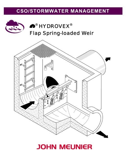
<strong>CSO</strong>/<strong>STORMWATER</strong> MANAGEMENT<br />
<strong>®</strong><br />
HYDROVEX <strong>®</strong><br />
<strong>Flap</strong> <strong>Spring</strong>-<strong>loaded</strong> <strong>Weir</strong>
HYDROVEX <strong>®</strong> FLAP SPRING-LOADED WEIR<br />
APPLICATION<br />
All Combined Sewer Systems have overflow points to the outfall. When a defined water level is exceeded in the system, the surplus<br />
water is overflowed to the receiving waters to avoid overloading of the Sewer Line and WWTP. Most overflow points are<br />
equipped with fixed static weirs. The allowable water height used to set the weir level w o is defined by the acceptable upstream<br />
backflow in the sewer line with the design flow Q b dimensioning = Q bü and the length of weir L.<br />
The height of the w o weir influences the passive capacity of retention of the line, which is the paramount factor in stormwater<br />
retention calculation. To reach an optimal use of the retention volume, long static weirs and their related civil work are required.<br />
With the HYDROVEX <strong>®</strong> <strong>Flap</strong> <strong>Spring</strong>-<strong>loaded</strong> <strong>Weir</strong>, we present a new type of level control device that is more powerful than a<br />
normal static weir. The spring-<strong>loaded</strong> weir can limit the required water level increase over the weir in order to generate a large<br />
overflow. Consequently, more retention volume in the sewer line is gained, while maintaining a safe level of water upstream<br />
(Figure 1). Contrary to the standard sharp crested weir, water can be overflowed without sucking out the sediment bed load from<br />
the sewer line.<br />
CONSTRUCTION<br />
The HYDROVEX <strong>®</strong> <strong>Flap</strong> <strong>Spring</strong>-<strong>loaded</strong> <strong>Weir</strong> is self-regulating and does not require external energy. Its stainless steel bow-shaped<br />
construction is very rigid in torsion and bending. The return mechanism consists of stainless steel compression springs installed<br />
under the weir to save space. The unit does not require cables, counterweight, bevel gearboxes and rotating shafts, resulting in a<br />
great reliability, long parts life and minimal maintenance.<br />
The construction of the spring-<strong>loaded</strong> weir is represented in Figure 2. A main beam, (1) made up of a profile sheet in the shape of a<br />
z, folded in two, is attached by shafts to the back of the concrete weir. We calculate the exact installation elevation of the unit<br />
according to each project to generate the appropriate retention level.<br />
The flap plate (2) pivots on bearings attached to the main beam. The flap plate is composed of reinforcing beams tied to the spring<br />
supports (3). The bearings of the weir (4) are made of stainless steel and designed for large loads. The return mechanism includes<br />
one or more springs (5) made of stainless steel. The springs are built on a spring internal guide (6). The geometry of construction<br />
and the characteristics of the springs guarantee the flow curve.<br />
The side plates of the spring-<strong>loaded</strong> weir are made of PEHD elements (7). These can be connected to the main beam and<br />
maintained by ties or be anchored directly on the existing side walls. The anchoring system supplies leveling to guarantee a reduced<br />
friction of the side elastomer EPDM joints (8) made to resist wastewater and frost.<br />
Figure 1: Demonstration of the efficiency of the<br />
HYDROVEX <strong>®</strong> <strong>Flap</strong> <strong>Spring</strong>-<strong>loaded</strong> <strong>Weir</strong><br />
compared to a static weir<br />
Figure 2: Sections of the HYDROVEX <strong>®</strong> <strong>Flap</strong><br />
<strong>Spring</strong>-<strong>loaded</strong> <strong>Weir</strong><br />
A gap of 1” to 1 ¼” between the side plates and the concrete wall is required. This gap serves mainly to adjust the unit inside the<br />
concrete openings work, but also as ventilation of the water flow, which passes over the weir to limit the oscillation of the unit. The<br />
gap is sealed to the upstream side by plastic strips to prevent water leaks.<br />
The main beam (1) is sealed in place with grout (9). This also supplies good support for the vertical loads on the unit.
OPERATION<br />
The construction simplicity of the HYDROVEX <strong>®</strong> <strong>Flap</strong> <strong>Spring</strong>-<strong>loaded</strong> <strong>Weir</strong> guarantees great reliability and allows for quick<br />
assembly. The form of the weir, the choice of material, as well as return mechanism conception, is the result of numerous<br />
laboratory tests and calculations. Behind this very simple construction is a very complex relationship between the static and<br />
dynamic hydraulic forces of the overflow water and the passive compression load of the springs in each position of the weir.<br />
Resting Position:<br />
When the HYDROVEX <strong>®</strong> <strong>Flap</strong> <strong>Spring</strong>-<strong>loaded</strong> <strong>Weir</strong> is in resting position, the pre-stressed springs are at full extension as long as<br />
there is no water level increase.<br />
Beginning of overflow:<br />
When the activation water level w min is reached, the hydrostatic forces of water make the weir yield downwards. The dynamic<br />
forces involved compress the spring mechanism to a new balance position.<br />
Rising Water Level:<br />
If the water level increases slightly, then the spring-<strong>loaded</strong> weir will yield more to the bottom and increase the water discharge<br />
section. The load curve in this case is practically horizontal (Figure 5), meaning that there is almost no water level increase, even<br />
though the discharged volume of water increases rapidly.<br />
Maximum flow:<br />
At maximum capacity, the spring-<strong>loaded</strong> weir is pressed against a mechanical stop unit, which limits the maximum bending. It is<br />
possible to overload the weir after this extreme position is reached and a much more significant flow can be created. However, once<br />
the springs are completely compressed, the flow can continue to increase, in spite of a reduction of effectiveness, it remains more<br />
efficient than a fixed weir, see Figure 5.<br />
Decreasing Water Level:<br />
When the flow decreases, the water level drops slowly and the forces on the weir are slackened. The weir progressively goes back<br />
to its resting position. As soon as the home position is reached, the overflow stops.<br />
The HYDROVEX <strong>®</strong> <strong>Flap</strong> <strong>Spring</strong>-<strong>loaded</strong> <strong>Weir</strong> shows a light and inevitable friction on the side supports, creating a small hysteresis<br />
of load Δh hy , like all valve-type level regulators without external energy. This implies that the level of water at end of discharge is<br />
somewhat lower than at beginning of discharge. However, due to its construction quality, the HYDROVEX <strong>®</strong> <strong>Flap</strong> <strong>Spring</strong>-<strong>loaded</strong><br />
<strong>Weir</strong> has a minimum friction and this hysteresis is limited to only some fraction of inches of the available water height, thus causing<br />
no operation problem. A certain hysteresis caused by friction is even necessary, as it prevents dynamic problems such as<br />
oscillations of the weir (damping effect of the spring motion).<br />
Figure 3 : Various operating phases of the spring overflow
We bring your attention to the fact that this device will cause brutal and<br />
sudden overflows. This implies that public security must be checked as well<br />
as the overall evacuation capacity of the downstream structures.<br />
Backwash prevention:<br />
The spring-<strong>loaded</strong> weir, subject to a backflow from the downstream side, can<br />
be modified to prevent water from returning in the sewer line. A higher lip<br />
seal is then added where the spring-<strong>loaded</strong> weir is in a resting position. The<br />
side plates for this option are strengthened to resist water loads in one way or<br />
the other. The spring-<strong>loaded</strong> weir can thus be used as a backflow prevention<br />
unit.<br />
MEASURE OF DISCHARGE<br />
Figure 4:<br />
Use of HYDROVEX <strong>®</strong> <strong>Flap</strong> <strong>Spring</strong>-<strong>loaded</strong><br />
<strong>Weir</strong> as backwash device<br />
The measure of overflowed water can be done by using the relationship between the angle of bending of the weir and the flow that<br />
passes the weir at a relatively constant water level. To do this, the weir plate has to be supplied with an angle indicator fixed on the<br />
body of the weir. Water passes over the weir only when it is not in resting position. If only the number and the duration of the<br />
activity of the discharge are required, then a limit switch is enough instead of the angle indicator.<br />
MODELS AVAILABLE<br />
Three standard models of HYDROVEX <strong>®</strong> <strong>Flap</strong> <strong>Spring</strong>-<strong>loaded</strong> <strong>Weir</strong>s are available and are represented in the table below. The<br />
specific design flow, indicated Q per meter length, is the flow for which the weir is in maximum bending position. The flows of<br />
weirs FSK 300 and FSK 700 meets chart ATV A 166, concerning the maximum allowable flows of the outfalls.<br />
Specific Design<br />
Type Flow Q<br />
ls-m (cfs)<br />
FSK 300 300 (10.6)<br />
FSK 465 465 (16.4)<br />
FSK 700 700 (24.7)<br />
Figure 5: Flow chart of the HYDROVEX <strong>®</strong> <strong>Flap</strong> <strong>Spring</strong>-<strong>loaded</strong> <strong>Weir</strong><br />
John Meunier Inc.<br />
ISO 9001 : 2000<br />
Head Office<br />
4105 Sartelon<br />
Saint-Laurent (Quebec) Canada H4S 2B3<br />
Tel.: 514-334-7230 www.johnmeunier.com<br />
Fax: 514-334-5070 cso@johnmeunier.com<br />
Ontario Office<br />
2000 Argentia Road, Plaza 4, Unit 430<br />
Mississauga (Ontario) Canada L5N 1W1<br />
Tel.: 905-286-4846 www.johnmeunier.com<br />
Fax: 905-286-0488 ontario@johnmeunier.com<br />
USA Office<br />
2209 Menlo Avenue<br />
Glenside, PA USA 19038<br />
Tel.: 412- 417-6614 www.johnmeunier.com<br />
Fax: 215-885-4741 asteele@johnmeunier.com<br />
Revised : 2008-10-01