Installation & Operating Instructions - Sweepsusa.net
Installation & Operating Instructions - Sweepsusa.net
Installation & Operating Instructions - Sweepsusa.net

You also want an ePaper? Increase the reach of your titles
YUMPU automatically turns print PDFs into web optimized ePapers that Google loves.
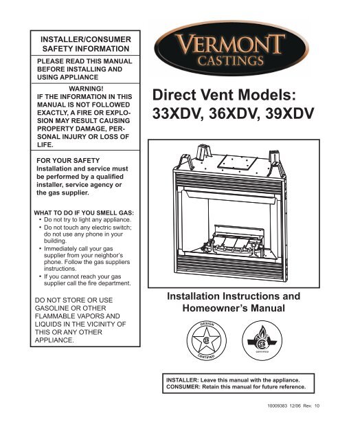
INSTALLER/CONSUMER<br />
SAFETY INFORMATION<br />
PLEASE READ THIS MANUAL<br />
BEFORE INSTALLING AND<br />
USING APPLIANCE<br />
WARNING!<br />
IF THE INFORMATION IN THIS<br />
MANUAL IS NOT FOLLOWED<br />
EXACTLY, A FIRE OR EXPLO-<br />
SION MAY RESULT CAUSING<br />
PROPERTY DAMAGE, PER-<br />
SONAL INJURY OR LOSS OF<br />
LIFE.<br />
Direct Vent Models:<br />
33XDV, 36XDV, 39XDV<br />
FOR YOUR SAFETY<br />
<strong>Installation</strong> and service must<br />
be performed by a qualified<br />
installer, service agency or<br />
the gas supplier.<br />
WHAT TO DO IF YOU SMELL GAS:<br />
• Do not try to light any appliance.<br />
• Do not touch any electric switch;<br />
do not use any phone in your<br />
building.<br />
• Immediately call your gas<br />
supplier from your neighbor’s<br />
phone. Follow the gas suppliers<br />
instructions.<br />
• If you cannot reach your gas<br />
supplier call the fire department.<br />
DO NOT STORE OR USE<br />
GASOLINE OR OTHER<br />
FLAMMABLE VAPORS AND<br />
LIQUIDS IN THE VICINITY OF<br />
THIS OR ANY OTHER<br />
APPLIANCE.<br />
<strong>Installation</strong> <strong>Instructions</strong> and<br />
Homeowner’s Manual<br />
DESIGN<br />
CERTIFIED<br />
9383<br />
XDV cover<br />
CERTIFIED<br />
5/06<br />
INSTALLER: Leave this manual with the appliance.<br />
CONSUMER: Retain this manual for future reference.<br />
10009383 12/06 Rev. 10
XDV Direct Vent Gas Fireplace<br />
Table of Contents<br />
PLEASE READ THE INSTALLATION & OPERATING INSTRUCTIONS<br />
BEFORE USING APPLIANCE.<br />
Thank you and congratulations on your purchase of a CFM Corporation fireplace.<br />
IMPORTANT: Read all instructions and warnings carefully before starting installation.<br />
Failure to follow these instructions fully may result in a possible fire hazard and will void the warranty.<br />
<strong>Installation</strong> & <strong>Operating</strong> <strong>Instructions</strong><br />
Important Curing/Burning <strong>Instructions</strong> .................................................................................................3<br />
Locating Your Fireplace .......................................................................................................................3<br />
Fireplace Dimensions ..........................................................................................................................4<br />
Clearance to Combustibles .................................................................................................................6<br />
Mantels .............................................................................................................................................6<br />
Hearth .............................................................................................................................................6<br />
Framing and Finishing .........................................................................................................................7<br />
Final Finishing .....................................................................................................................................7<br />
Gas Specifications ...............................................................................................................................7<br />
Gas Inlet and Manifold Pressures .......................................................................................................7<br />
High Elevations ....................................................................................................................................7<br />
Gas Line <strong>Installation</strong> ............................................................................................................................7<br />
Remote ON/OFF Switch ......................................................................................................................8<br />
Alternate Switch Location ....................................................................................................................8<br />
EB-1 Electrical Box ..............................................................................................................................8<br />
Electronic Gas Control Valve ...............................................................................................................9<br />
Optional Top Vent Application ............................................................................................................10<br />
Top Vent Application Restrictor Plate .................................................................................................11<br />
General Venting Information<br />
General Venting .................................................................................................................................11<br />
General Venting Information-Termination Location ...........................................................................12<br />
General Information Assembling Vent Pipes .....................................................................................13<br />
Flex Vent Pipes ..................................................................................................................................13<br />
Twist Lock Pipes ................................................................................................................................14<br />
How to Use the Vent Graph ...............................................................................................................14<br />
Rear Wall Venting Applications & <strong>Installation</strong> ....................................................................................14<br />
Vertical Sidewall Applications & <strong>Installation</strong> .......................................................................................16<br />
Below Grade <strong>Installation</strong> ....................................................................................................................20<br />
Vertical Through-the-Roof Applications & <strong>Installation</strong> ........................................................................20<br />
Venting Components .........................................................................................................................23<br />
<strong>Operating</strong> <strong>Instructions</strong><br />
Glass Information ..............................................................................................................................24<br />
Louvre Removal ................................................................................................................................24<br />
Window Frame Assembly Removal ...................................................................................................24<br />
Glass Cleaning ..................................................................................................................................24<br />
Replacement of Ceramic Hearth Panels ...........................................................................................24<br />
<strong>Installation</strong> of Logs and Lava Rock ....................................................................................................25<br />
Flame & Temperature Adjustment .....................................................................................................30<br />
Manual ON/OFF Valve ......................................................................................................................30<br />
Flame Characteristics ........................................................................................................................30<br />
Inspecting the Venting System ..........................................................................................................30<br />
Lighting and <strong>Operating</strong> <strong>Instructions</strong> ...................................................................................................32<br />
<strong>Instructions</strong> for RF Comfort Control Valve .........................................................................................34<br />
Troubleshooting .................................................................................................................................38<br />
Fuel Conversion <strong>Instructions</strong> .............................................................................................................40<br />
Maintenance<br />
Cleaning the Standing Pilot Control System ......................................................................................45<br />
Replacement Parts ...................................................................................................................................46<br />
Optional Accessories<br />
Fan Kits ...........................................................................................................................................49<br />
Remote Controls ................................................................................................................................50<br />
Ceramic Refractory Panels ................................................................................................................50<br />
Trim Kits, Screen Door Kit, Filigree Louvre Kit ..................................................................................51<br />
Warranty .......................................................................................................................................................55<br />
2<br />
Energuide ....................................................................................................................................................56<br />
10009383
<strong>Installation</strong> & <strong>Operating</strong> <strong>Instructions</strong><br />
This gas appliance should be installed by a qualified<br />
installer in accordance with local building codes and with<br />
current CSA-B149.1 <strong>Installation</strong> codes for Gas Burning<br />
Appliances and Equipment. For USA <strong>Installation</strong>s follow<br />
local codes and/or the current National Fuel Gas Code.<br />
ANSI Z223.1/NFPA 54.<br />
In the Commonwealth of Massachusetts, all gas fitting<br />
and installation of this heater shall only be done by a<br />
licensed gas fitter or licensed plumber.<br />
FOR SAFE INSTALLATION AND OPERATION PLEASE<br />
NOTE THE FOLLOWING:<br />
1. This fireplace gives off high temperatures and should be<br />
located out of high traffic areas and away from furniture and<br />
draperies.<br />
2. Children and adults should be alerted to the hazards of high<br />
surface temperatures of this fireplace and should stay away<br />
to avoid burns or ignition of clothing.<br />
3. CAUTION: Due to high glass surface temperature children<br />
should be carefully supervised when in the same<br />
room as fireplace.<br />
4. Under no circumstances should this fireplace be modified.<br />
Parts removed for servicing should be replaced prior to<br />
operating this fireplace again.<br />
5. <strong>Installation</strong> and any repairs to this fireplace must be performed<br />
by a qualified installer, service agency or gas supplier.<br />
A professional service person should be contacted to<br />
inspect this fireplace annually. Make it a practice to have<br />
all of your gas fireplaces checked annually. More frequent<br />
cleaning may be required due to excess lint and dust from<br />
carpeting, bedding material, etc.<br />
6. Control compartments, burners and air passages in this fireplace<br />
should be kept clean and free of dust and lint. Make<br />
sure the gas valve and pilot light are turned off before you<br />
attempt to clean this fireplace.<br />
7. The venting system (chimney) of this fireplace should be<br />
checked at least once a year and if needed your venting<br />
system should be cleaned.<br />
8. Keep the area around your fireplace clear of combustible<br />
materials, gasoline and other flammable vapor and liquids.<br />
This fireplace should not be used as a drying rack for clothing,<br />
nor should Christmas stockings or decorations be hung<br />
on or around the fireplace.<br />
9. Under no circumstances should any solid fuels (wood, coal,<br />
paper or cardboard etc.) be used in this fireplace.<br />
10. The flow of combustion and ventilation air must not be obstructed<br />
in any way.<br />
11. When fireplace is installed directly on carpeting, vinyl tile<br />
or any combustible material other than wood, the fireplace<br />
must be installed on a metal or wood panel extending the<br />
full width and depth of the fireplace.<br />
12. This fireplace requires adequate ventilation and combustion<br />
air to operate properly.<br />
13. This fireplace must not be connected to a chimney flue<br />
serving a separate solid fuel burning fireplace.<br />
14. When the fireplace is not in use it is recommended that the<br />
gas valve be left in the OFF position.<br />
WARNING: Check with your electronics manufacturer<br />
before installing a television or other electronic device<br />
above this fireplace.<br />
XDV Direct Vent Gas Fireplace<br />
This appliance may be installed in an aftermarket permanently<br />
located, manufactured home or mobile home,<br />
where not prohibited by local codes.<br />
This appliance is only for use with the type of gas indicated<br />
on the rating plate. This appliance is not convertible<br />
for use with other gases, unless a certified kit is used.<br />
IMPORTANT:<br />
PLEASE REVIEW THE FOLLOWING CAREFULLY<br />
Remove any plastic from trim parts before turning the<br />
fireplace ON.<br />
It is normal for fireplaces fabricated of steel to give off<br />
some expansion and/or contraction noises during the<br />
start up or cool down cycle. Similar noises are found<br />
with your furnace heat exchanger or car engine.<br />
It is not unusual for your gas fireplace to give off some<br />
odor the first time it is burned. This is due to the curing of<br />
the paint and any undetected oil from the manufacturing<br />
process.<br />
Please ensure that your room is well ventilated -<br />
open all windows.<br />
It is recommended that you burn your fireplace for at<br />
least ten (10) hours the first time you use it. If the optional<br />
fan kit has been installed, place the fan switch in the<br />
“OFF” position during this time.<br />
Fig. 1 Locate gas fireplace.<br />
Locating Your Fireplace<br />
A) Flat on wall B) Cross corner C) **Island<br />
D) *Room divider E) *Flat on wall corner F) Chase installation<br />
Y) 6” minimum<br />
NOTE: (fig. 1)<br />
** Island (C) and Room Divider (D) installation is possible as<br />
long as the horizontal portion of the vent system (X) does not<br />
exceed 20’ (610 cm). See details in Venting Section.<br />
* When you install your fireplace in(D) Room divider or (E) Flat<br />
on wall corner positions (Y), a minimum of 6” (153 mm) clearance<br />
must be maintained from the perpendicular wall and the<br />
front side edge of the fireplace.<br />
Refer to (Y) in Figure 1.<br />
10009383 3<br />
Y<br />
Y<br />
E<br />
D<br />
F<br />
A<br />
C<br />
X<br />
B<br />
B<br />
LU584-1<br />
Locating unit<br />
2/4/99 djt<br />
LU584-R
XDV Direct Vent Gas Fireplace<br />
XDV Fireplace Dimensions - Installed as Rear Vent<br />
Rough<br />
Opening<br />
Depth<br />
E<br />
4" Dia. (102mm)<br />
7" Dia. (178mm)<br />
S<br />
X<br />
F<br />
Recessed<br />
Nailing<br />
Flange<br />
S<br />
U<br />
5/8" (16 mm)<br />
T<br />
Rough<br />
Opening<br />
Height<br />
V - Rough Opening Width<br />
5/8" (16mm)<br />
G<br />
B<br />
Low Voltage<br />
Electrical<br />
Access<br />
Gas Line<br />
Access<br />
W<br />
C<br />
D<br />
B<br />
Electrical<br />
Access<br />
Low Voltage<br />
Electrical<br />
Access<br />
Gas Line<br />
Access<br />
H<br />
I<br />
M<br />
M N<br />
O<br />
P<br />
A<br />
J<br />
K<br />
L<br />
Fig. 2 Fireplace specifications and framing dimensions.<br />
Ref. 33XDV 792036XDV 39 XDV<br />
A 33” (838 mm) XDV 36” rear (914 specs mm) 39” (991 mm)<br />
B 28⁷⁄₈” (733 mm)<br />
2/05<br />
34¹⁄₄” (870 mm) 34¹⁄₄” (870 mm)<br />
C 31¹⁄₄” (794 mm) 34¹⁄₄” (870 mm) 37¹⁄₄” (946 mm)<br />
D 18³⁄₈” (466 mm) 23” (584 mm) 23” (584 mm)<br />
E 22³⁄₄” (578 mm) 24” (610 mm) 27” (686 mm)<br />
F 14³⁄₈” (365 mm) 16¹⁄₄” (413 mm) 16¹⁄₄” (413 mm)<br />
G 16³⁄₄” (426 mm) 18³⁄₄” (476 mm) 18³⁄₄” (476 mm)<br />
H 19³⁄₁₆” (487 mm) 24¹⁄₄” (616 mm) 24¹⁄₄” (616 mm)<br />
I 22¹¹⁄₁₆” (576 mm) 28¹⁄₈” (714 mm) 28¹⁄₈” (714 mm)<br />
J 4⁵⁄₈” (118 mm) 5⁵⁄₈” (143 mm) 5⁵⁄₈” (143 mm)<br />
K 6³⁄₈” (160 mm) 8” (203 mm) 8” (203 mm)<br />
L 8⁷⁄₈” (225 mm) 11⁷⁄₈” (302 mm) 11⁷⁄₈” (302 mm)<br />
M 2” (51 mm) 2” (51 mm) 2” (51 mm)<br />
N 3³⁄₈” (85 mm) 3¹⁄₄” (82 mm) 3¹⁄₄” (82 mm)<br />
O 4⁵⁄₈” (118 mm) 6³⁄₄” (171 mm) 6³⁄₄” (171 mm)<br />
P 6³⁄₈” (162 mm) 9¹⁄₄” (235 mm) 9¹⁄₄” (235 mm)<br />
Framing Dimensions<br />
S 36” (914 mm) 41⁵⁄₈” (1057 mm) 44” (1118 mm)<br />
T 51” (1295 mm) 58⁷⁄₈” (1495 mm) 62¹⁄₄” (1581 mm)<br />
U 25¹⁄₄” (641 mm) 29⁷⁄₈” (748 mm) 31¹⁄₈” (790 mm)<br />
V 33¹⁄₂” (851 mm) 36¹⁄₂” (927 mm) 39¹⁄₂” (1003 mm)<br />
W 31” (787 mm) 38⁵⁄₈” (980 mm) 38⁵⁄₈” (980 mm)<br />
X 14⁷⁄₈” (378 mm) 16³⁄₄” (426 mm) 16³⁄₄” (426 mm)<br />
4 10009383
XDV Direct Vent Gas Fireplace<br />
XDV Fireplace Dimensions - Installed as Top Vent<br />
Rough<br />
Opening<br />
Depth<br />
E<br />
7" Dia. (178mm)<br />
4" Dia. (102mm)<br />
S<br />
X<br />
F<br />
R<br />
Recessed<br />
Nailing<br />
Flange<br />
S<br />
U<br />
T<br />
5/8" (16 mm)<br />
Rough<br />
Opening<br />
Height<br />
V - Rough Opening Width<br />
5/8" (16mm)<br />
Q<br />
B<br />
Low Voltage<br />
Electrical<br />
Access<br />
Gas Line<br />
Access<br />
W<br />
C<br />
D<br />
B<br />
Electrical<br />
Access<br />
Low Voltage<br />
Electrical<br />
Access<br />
Gas Line<br />
Access<br />
N<br />
O<br />
P<br />
M<br />
A<br />
J<br />
K<br />
L<br />
M<br />
Fig. 3 Fireplace specifications and framing dimensions.<br />
Ref. 33XDV 36XDV 39XDV<br />
A 33” (838 mm) 36” (914 mm) 39” (991 mm)<br />
B 28⁷⁄₈” (733 mm) 34¹⁄₄” (870 mm) 34¹⁄₄” (870 mm)<br />
7920<br />
C 31¹⁄₄” (794 mm) 34¹⁄₄” (870 mm) 37¹⁄₄” (946 mm)<br />
XDV top specs<br />
D 18³⁄₈” (466 mm) 23” (584 mm) 23” (584 mm)<br />
E 22³⁄₄” (578 mm) 2/05 24” (610 mm) 27” (686 mm)<br />
F 14³⁄₈” (365 mm) 16¹⁄₄” (413 mm) 16¹⁄₄” (413 mm)<br />
G -- -- -- -- -- --<br />
H -- -- -- -- -- --<br />
I -- -- -- -- -- --<br />
J 4⁵⁄₈” (118 mm) 5⁵⁄₈” (143 mm) 5⁵⁄₈” (143 mm)<br />
K 6³⁄₈” (162 mm) 8” (203 mm) 8” (203 mm)<br />
L 8⁷⁄₈” (225 mm) 11⁷⁄₈” (302 mm) 11⁷⁄₈” (302 mm)<br />
M 2” (51 mm) 2” (51 mm) 2” (51 mm)<br />
N 3³⁄₈” (85 mm) 3¹⁄₄” (82 mm) 3¹⁄₄” (82 mm)<br />
O 4⁵⁄₈” (117 mm) 6³⁄₄” (171 mm) 6³⁄₄” (171 mm)<br />
P 6³⁄₈” (162 mm) 9¹⁄₄” (235 mm) 9¹⁄₄” (235 mm)<br />
Q 31³⁄₄” (806 mm) 37” (939 mm) 37” (939 mm)<br />
R 6⁵⁄₃₂” (156 mm) 6³⁄₄” (170 mm) 6³⁄₄” (170 mm)<br />
Framing Dimensions<br />
S 36” (914 mm) 39³⁄₄” (1010 mm) 43¹⁄₈” (1045 mm)<br />
T 51” (1295 mm) 55¹⁄₄” (1403 mm) 60⁷⁄₈” (1546 mm)<br />
U 25¹⁄₄” (641 mm) 28¹⁄₈” (714 mm) 30⁷⁄₈” (784 mm)<br />
V 33¹⁄₂” (851 mm) 36¹⁄₂” (927 mm) 39¹⁄₂” (1003 mm)<br />
W 31” (787 mm) 38⁵⁄₈” (980 mm) 38⁵⁄₈” (980 mm)<br />
X 14⁷⁄₈” (378 mm) 16³⁄₄” (426 mm) 16³⁄₄” (426 mm)<br />
10009383 5
XDV Direct Vent Gas Fireplace<br />
Clearance to Combustibles<br />
Top of Unit to Ceiling ................................36” (914 mm)<br />
Front of Unit to Combustibles ...................36” (914 mm)<br />
Appliance<br />
Top of Standoff .........................................0” (0 mm)<br />
Bottom ......................................................0” (0 mm)<br />
Side ..........................................................0” (0 mm)<br />
Back .........................................................0” (0 mm)<br />
Venting<br />
Concentric sections of DV Vent ....................1” (25 mm)<br />
Nonconcentric sections of DV Vent<br />
Sides and Bottom ...................................1” (25 mm)<br />
Top .........................................................2” (51 mm)<br />
Mantels<br />
The height that a combustible mantel is fitted above the<br />
fireplace is dependent on the depth of the mantel. This<br />
also applies to the distance between the mantel leg (if<br />
fitted) and the fireplace.<br />
For the correct mounting height and widths refer to<br />
Figs. 4a and 4b, and the following Mantel Charts.<br />
The fitting of a bay window trim kit does not effect<br />
the distances and reference points referred to in the<br />
diagram and chart.<br />
Noncombustible mantels and legs may be installed<br />
at any height and width around the appliance. When<br />
using paint or lacquer to finish the mantel, such paint or<br />
lacquer must be heat resistant to prevent discoloration.<br />
A B C D E<br />
V<br />
W<br />
X<br />
Y<br />
Z<br />
CFM146<br />
DV Mantel Chart<br />
7/5/01 sta<br />
Fireplace<br />
Mantel Chart<br />
Mantel Shelf<br />
Ref. or Breastplate<br />
V 10” (254 mm)<br />
W 8” (203 mm)<br />
X 6” (152 mm)<br />
Y 4” (101 mm)<br />
Z 2” (51 mm)<br />
Maintain minimum 3/4”<br />
(19 mm) clearance to<br />
combustible<br />
Louvre Assembly<br />
Top<br />
Top of Combustion<br />
Chamber<br />
Fig. 4a Combustible mantel minimum installation.<br />
CFM146<br />
Ref. Mantel from Top of Combustion Chamber<br />
33XDV 36XDV 39XDV<br />
A 18¹⁄₂” (470 mm) 19” (482 mm) 20” (508 mm)<br />
B 16¹⁄₂” (419 mm) 17” (432 mm) 18” (457 mm)<br />
C 14¹⁄₂” (368 mm) 15” (381 mm) 16” (406 mm)<br />
D 12¹⁄₂” (318 mm) 13” (330 mm) 14” (355 mm)<br />
E 10¹⁄₂” (267 mm) 11” (279 mm) 12” (305 mm<br />
CFM164a<br />
Black<br />
Surround<br />
Face<br />
Side of<br />
Combustion Chamber<br />
CFM164a<br />
Mantel Leg Chart<br />
06/22/01 sta<br />
Mantel<br />
Leg<br />
J<br />
M LK<br />
N<br />
O<br />
I<br />
H<br />
G<br />
F<br />
CFM170<br />
Mantel<br />
Mantel Leg FromSide<br />
Ref. Leg Depth Ref. of Comb. Opening<br />
F<br />
CFM170<br />
10” (254 DV mm) Builder Front K 11¹⁄₂” (292 mm)<br />
G 8” (203<br />
View<br />
mm) L 9¹⁄₂” (241 mm)<br />
H 6” (152 mm) M 7¹⁄₂” (191 mm)<br />
I 4” (101 mm) N 5¹⁄₂” (140 mm)<br />
J 2” (51 mm) O 3¹⁄₂” (89 mm)<br />
Fig. 4b Combustible mantel leg minimum installation.<br />
Hearth<br />
A hearth is not mandatory but is recommended for<br />
aesthetic purposes. We recommend a noncombustible<br />
hearth which projects out 12” (305 mm) or more from<br />
the front of the fireplace.<br />
Cold climate installation recommendation:<br />
When installing this unit against a<br />
non-insulated exterior wall or chase,<br />
it is mandatory that the outer walls<br />
be insulated to conform to applicable<br />
insulation codes.<br />
Proposition 65 Warning: Fuels used in gas, woodburning<br />
or oil fired appliances, and the products of<br />
combustion of such fuels, contain chemicals known to<br />
the State of California to cause cancer, birth defects<br />
and other reproductive harm.<br />
California Health & Safety Code Sec. 25249.6<br />
6 10009383
XDV Direct Vent Gas Fireplace<br />
Framing and Finishing<br />
Check fireplace to make sure it is levelled<br />
and properly positioned.<br />
To mount the appliance:<br />
1. Choose the location.<br />
2. This unit comes with four (4) flanges pre-mounted<br />
on both sides of the fireplace to allow two different<br />
drywall thicknesses to be used. Flange “A” is for<br />
1/2” drywall while flange “B” is for 5/8” drywall.<br />
3. Bend the desired flanges out 90° on both sides of<br />
the fireplace. Slide the fireplace into the framed<br />
opening until the flanges contact the front surfaces<br />
of the framing. Level the unit and secure it firmly in<br />
place.<br />
Flange<br />
Position<br />
A<br />
B<br />
A<br />
Drywall<br />
Depth<br />
1/2” / 13 mm<br />
5/8” / 16 mm<br />
B<br />
Fig. 5 Nailing flanges.<br />
Final Finishing<br />
Flange Location for<br />
Desired Drywall Depth<br />
FP1539a<br />
flanges w/standoffs<br />
FP1539<br />
Noncombustible materials such 5/05as brick or tile may be<br />
extended over the edges of the face of the fireplace.<br />
DO NOT cover any vent or grille panels.<br />
If a Trim Kit is going to be installed on the fireplace, the<br />
brick or tile will have to be installed flush with the edges<br />
of the fireplace.<br />
33XDV / 36XDV / 39XDV<br />
Certified To<br />
ANSI Z21.88-2005 / CSA 2.33-2005<br />
Vented Gas Fireplace Heaters<br />
Units: GFDN3L1, GFDE3L1, GFDN3J1, GFDI3J1,<br />
GFDE3JI, GFDN3K1, GFDE3K1<br />
Gas Specifications<br />
Max. Min.<br />
Input Input<br />
Model Fuel Gas Control BTU/h BTU/h<br />
33XDVRN Nat. Millivolt Hi/Lo 21,500 4,400<br />
33XDVRP Prop. Millivolt Hi/Lo 21,500 5,425<br />
33XDVEN Nat. 24 Volt Hi/Lo 21,500 4,400<br />
33XDVEP Prop. 24 Volt Hi/Lo 21,500 5,425<br />
36XDVRN Nat. Millivolt Hi/Lo 27,500 5,150<br />
36XDVRP Prop. Millivolt Hi/Lo 27,500 5,500<br />
36XDVRFN Nat. Comfort Contrl 27,500 5,810<br />
36XDVRFP Prop. Comfort Contrl 27,500 6,225<br />
36XDVEN Nat. 24 Volt Hi/Lo 27,500 5,150<br />
36XDVEP Prop. 24 Volt Hi/Lo 27,500 5,500<br />
39XDVRN Nat. Millivolt Hi/Lo 30,000 6,700<br />
39XDVRP Prop. Millivolt Hi/Lo 30,000 5,800<br />
39XDVEN Nat 24 Volt Hi/Lo 30,000 6,700<br />
39XDVEP Prop 24 Volt Hi/Lo 30,000 5,800<br />
Gas Inlet and Manifold Pressures<br />
Natural LP (Propane)<br />
Inlet Minimum 5.5” w.c. 11.0” w.c.<br />
Inlet Maximum 14.0” w.c. 14.0” w.c.<br />
Manifold Pressure 3.5” w.c. 10.0” w.c.<br />
High Elevations<br />
Input ratings are shown in BTU per hour and are<br />
certified without deration for elevations up to<br />
4,500 feet (1,370m) above sea level.<br />
For elevations above 4,500 feet (1,370m) in USA,<br />
installations must be in accordance with the current<br />
ANSI Z223.1/NFPA 54 and/or local codes having<br />
jurisdiction.<br />
In Canada, please consult provincial and/or local<br />
authorities having jurisdiction for installations at<br />
elevations above 4,500 feet (1,370m).<br />
Gas Line <strong>Installation</strong><br />
When purging the gas lines, the front window<br />
frame assembly must be removed.<br />
The gas pipeline can be brought in through the rear<br />
of the appliance as well as the bottom. Knockouts are<br />
provided on the bottom behind the valve to allow for the<br />
gas pipe installation and testing of any gas connection.<br />
It is most convenient to bring the gas line in from the<br />
rear right side of the valve as this allows fan installation<br />
or removal without disconnecting the gas line.<br />
10009383 7
XDV Direct Vent Gas Fireplace<br />
The gas line connection can be made with properly<br />
tinned 3/8” copper tubing, 3/8” rigid pipe or an approved<br />
flex connector. Since some municipalities have<br />
additional local codes, it is always best to consult your<br />
local authority and the National Fuel Gas Code, ANSI<br />
Z223.1/NFPA 54 in the USA or the CSA-B149.1 installation<br />
code.<br />
2. Attach the wire to the ON/OFF switch and install<br />
switch into receptacle box. Attach cover plate to<br />
switch.<br />
3. Connect wiring to gas valve. (Fig. 7)<br />
Remote ON/OFF Switch<br />
1/2” Gas Supply<br />
1/2” NPT x 1/2” Flare Shutoff<br />
Valve<br />
3/8” Flex Line<br />
(From Valve)<br />
Fig. 7 Remote switch wiring diagram for R models.<br />
TPTH TP TH<br />
FP1218<br />
FP297A<br />
Fig. 6 Typical gas supply installation.<br />
Always check for gas leaks with a mild<br />
soap and water solution applied with a<br />
brush no larger than FP297A 1” (25 mm). Never<br />
INSTA VENT FREE<br />
apply soap and water solution with a spray<br />
UVHB26 GAS SUPPLY<br />
bottle. Do not use 7/1/98 an open flame for leak<br />
testing.<br />
The fireplace valve must not be subjected<br />
to any test pressures exceeding 1/2 psi.<br />
Isolate or disconnect this or any other gas<br />
appliance control form the gas line when<br />
pressure testing.<br />
The gas control is equipped with a captured screw type<br />
pressure test point, therefore it is not necessary to provide<br />
a 1/8” test point up stream of the control.<br />
When using copper or flex connector use only approved<br />
fittings. Always provide a union when using black iron<br />
pipe so the gas line can be easily disconnected for<br />
burner or fan servicing. See gas specification for pressure<br />
details and ratings.<br />
The fireplace valve must not be subjected to any test<br />
pressures exceeding 1/2 psi. Isolate or disconnect this<br />
and any other gas appliance control from the gas line<br />
when pressure testing.<br />
Remote ON/OFF Switch<br />
Do not wire the remote ON/OFF wall switch for this gas<br />
appliance into a 120v power supply.<br />
1. Thread wire through the electrical knockout located<br />
on either side of the unit. Take care not to cut the<br />
wire or insulation on metal edges. Ensure the wire is<br />
secured and protected form possible damage. Run<br />
one end of the gas control valve and the other end to<br />
the conveniently located wall switch.<br />
Alternate Switch Location<br />
The remote switch can be installed on the front/side<br />
of the access door. FP1218 Simply mount the switch to the<br />
bracket provided and Remote screw the switch bracket to either side<br />
of the frame, lining up the screws with the pre-punched<br />
wiring<br />
holes. (Fig. 8)<br />
8/02<br />
Fig. 8 Alternate switch location.<br />
EB-1 Electrical Box<br />
FP1024<br />
The fireplace, when installed, must be<br />
electrically connected and grounded in<br />
accordance with local<br />
alternate<br />
codes or, in the absence<br />
of local codes, remote with the switch current CSA<br />
C22.1 Canadian Electrical Code.<br />
location<br />
FP1024<br />
For USA installations follow local codes<br />
and the national electrical 1/27/00 code djt ANSI/<br />
NFPA No. 70.<br />
It is strongly suggested that the wiring of<br />
the EB-1 Electrical Junction Box be carried<br />
out by a licensed electrician.<br />
Ensure that the power to the supply line<br />
has been disconnected before commencing<br />
this procedure.<br />
8 10009383
XDV Direct Vent Gas Fireplace<br />
The EB-1 Electrical junction box has been fitted standard<br />
on this model to allow for the easy connection of an<br />
optional fan kit.<br />
To connect the EB-1 box to the house electrical supply<br />
follow the steps below.<br />
1. Unscrew the retaining screw from the EB-1 base<br />
plate and remove the EB-1 assembly from the<br />
appliance. (Fig. 9)<br />
2. Remove the front cover of the EB-1 box.<br />
3. Remove the plug socket assembly from the EB-1<br />
box.<br />
4. Feed the supply line in through the EB-1 opening in<br />
the side of the appliance and then through the back<br />
of the EB-1 assembly. (Fig. 9)<br />
5. Connect the black wire of the power supply line to<br />
the brass screw (polarized) of the socket assembly.<br />
6. Connect the white wire of the power line to the<br />
chrome screw of the socket assembly.<br />
7. Connect the ground wire of the supply line to the<br />
green screw of the socket assembly.<br />
8. Refit the socket assembly back into the electrical<br />
box and replace the cover plate. Secure the cable<br />
with the clamp on the outside of the EB-1 base<br />
plate and refit the EB-1 assembly to the unit with the<br />
screw removed in step 1.<br />
INSIDE<br />
FRONT OF UNIT<br />
OUTSIDE<br />
Fig. 9 EB-1 receptacle.<br />
Electrical Box<br />
FRONT OF UNIT<br />
Electronic Gas Control Valve<br />
FP580<br />
INSTA VENT FREE<br />
EB1 JUNCTION BOX<br />
11/18/97<br />
FP580<br />
This appliance may be fitted with a Sy<strong>net</strong>ek ignition<br />
module.<br />
<strong>Installation</strong> of the remote on/off starter switch or<br />
wall thermostat on electronic ignition units.<br />
1. Thread the wiring through the holes on the side<br />
panels of the appliance. Take care not to cut the wire<br />
or insulation on metal edges. Route the wire to a<br />
conveniently located receptacle box.<br />
2. Attach the wire to the ON/OFF switch and install the<br />
switch into the receptacle box.<br />
BLACK<br />
WHITE<br />
GREEN<br />
L1<br />
L2<br />
POWER CORD<br />
PURPLE<br />
PILOT SENSING<br />
PILOT IGNITER<br />
YELLOW<br />
M<br />
O<br />
P<br />
O<br />
CIRCUIT BOARD<br />
RED<br />
WHITE<br />
BLUE<br />
ORANGE<br />
VALVE<br />
ON/OFF SWITCH<br />
OR<br />
WALL THERMOSTAT<br />
Fig. 10 SIT822 Valve with Sy<strong>net</strong>ek electronic control wiring diagram.<br />
FP1571<br />
10009383 9<br />
FP1571
XDV Direct Vent Gas Fireplace<br />
3. Connect the white wire from the wall switch or wall<br />
thermostat to the white wire terminal from the electronic<br />
module. Connect the black wire from the wall<br />
switch or the red wire from the wall thermostat, to<br />
the red wire terminal from the electronic module.<br />
Remove Insulation 7”<br />
Diameter Notch Out<br />
Remove Screws (4)<br />
Optional Top Vent Application<br />
The 33/36/39XDV fireplaces are shipped as rear vent<br />
units. If the layout requires a top vent, convert the unit<br />
following the steps below.<br />
1. Remove the 10 screws securing outer collar adapter<br />
to fireplace. (Fig. 11)<br />
2. Set outer collar adapter aside.<br />
3. Carefully remove and discard the insulation directly<br />
below the 7” hole in the cabi<strong>net</strong> top. The insulation<br />
is perforated around the hole to aid in its removal.<br />
Remove the four (4) screws securing flue cover to<br />
top of unit and remove flue cover. (Fig. 12)<br />
4. Remove the four (4) screws securing the flue pipe assembly<br />
to the appliance. Remove flue pipe. (Fig. 12)<br />
5. Secure flue cover to back of flue outlet. (Fig. 13)<br />
6. Install flue pipe and gasket removed in step 4 to top<br />
of unit with four (4) screws. (Fig. 13)<br />
7. Secure outer collar adapter to unit with the round<br />
collar on top, secure with 10 screws. (Fig. 14)<br />
NOTE: Be sure not to damage any gasket material.<br />
Outer Collar<br />
Adapter<br />
Remove Screws<br />
(5)<br />
Flue Cover<br />
Remove Screws (4)<br />
Fig. 12 Remove flue cover and flue pipe.<br />
Flue Pipe<br />
Install Screws (4)<br />
Back in Place<br />
<br />
<br />
<br />
Install Screws (4)<br />
Back in Place<br />
Fig. 13 Replace flue cover and flue pipe.<br />
Flue<br />
Cover<br />
<br />
Install Screws (5)<br />
<br />
Back in Place<br />
<br />
FP1549<br />
FP1551<br />
Outer Collar Adapter<br />
Flue Pipe<br />
Remove<br />
Screws (5)<br />
Fig. 11 Remove screws from outer collar adapter.<br />
<br />
<br />
<br />
FP1458<br />
Install Screws (5)<br />
Back in Place<br />
Fig. 14 Completed conversion.<br />
FP1550<br />
After conversion to top vent configuration,<br />
the 4” (102 mm) flue pipe should be concentric<br />
within the 7” (175 mm) outer collar.<br />
<br />
10 10009383
Top Vent Application<br />
Restrictor Plate<br />
When the 33XDV or 36XDV models are installed as top<br />
vent fireplaces with a minimum 12” (305 mm) rise, the<br />
restrictor plate must be installed to give better flame<br />
appearance.<br />
This restrictor plate is shipped with the 33/36XDV and is<br />
located below the access control panel.<br />
33XDV Restrictor Plate <strong>Installation</strong><br />
1. Remove rear log bracket located behind the burner<br />
panel.<br />
2. Install the restrictor plate with the rear log using existing<br />
mounting holes and pre-attached screws from<br />
the rear log bracket. (Fig. 15)<br />
3. Install rear log bracket assembly by reversing Step 1.<br />
4. Install log set, ember materials, lava rock. Refer to<br />
log set installation section.<br />
36XDV Restrictor Plate <strong>Installation</strong><br />
1. Remover rear log bracket located behind the burner<br />
panel.<br />
2. Replace the deflector rear log bracket with the<br />
restrictor plate to the rear log bracket using existing<br />
mounting holes and screws. (Fig. 16) Discard deflector.<br />
3. Install rear log bracket assembly by reversing Step 1.<br />
4. Install log set, ember materials, lava rock. Refer to<br />
log set installation section.<br />
Your fireplace is approved to be vented either through<br />
the side wall, or vertically through the roof.<br />
• Only CFM Corporation venting components specifically<br />
approved and labelled for this fireplace may be<br />
used.<br />
• If vent termination is installed in an accessible location,<br />
Vent Termination Guard #53525 shall be installed.<br />
• Vent terminations shall not be recessed into a wall or<br />
siding.<br />
• Horizontal venting which incorporates the twist lock<br />
pipe must be installed on a level plane without an<br />
inclining or declining slope.<br />
• Horizontal venting which incorporates the use of flex<br />
venting shall have an inclining slope from the unit of<br />
1/2” (13 mm) per 12” (305 mm).<br />
Restrictor Plate<br />
General Venting<br />
XDV Direct Vent Gas Fireplace<br />
Rear Log Bracket<br />
Fig. 15 33XDV restrictor plate installation.<br />
Remove<br />
and Discard<br />
Deflector<br />
Restrictor Plate<br />
Rear Log Bracket<br />
<br />
<br />
<br />
Fig. 16 36XDV restrictor plate installation.<br />
FP1729<br />
FP1730<br />
<br />
<br />
<br />
There must not be any obstruction such as bushes,<br />
garden sheds, fences, decks or utility buildings within<br />
24” (610 mm) from the front of the termination hood.<br />
Do not locate termination hood where excessive snow<br />
or ice build up may occur. Be sure to check vent termination<br />
area after snow falls, and clear to prevent accidental<br />
blockage of venting system. When using snow<br />
blowers, make sure snow is not directed towards vent<br />
termination area.<br />
Location of Vent Termination<br />
It is imperative the vent termination be located observing<br />
the minimum clearances as shown on the next<br />
page.<br />
*Check with local codes or in absence of same with<br />
CSA B149.1 <strong>Installation</strong> Codes (1991) for Canada<br />
or follow the current National Fuel Gas Code, ANSI<br />
Z223.1/NFPA 54 for installations in the USA.<br />
10009383 11
XDV Direct Vent Gas Fireplace<br />
General Venting Information - Termination Location<br />
INSIDE<br />
CORNER DETAIL<br />
D<br />
V<br />
E<br />
A<br />
V<br />
G<br />
H<br />
N<br />
N<br />
L<br />
V<br />
B<br />
F<br />
C<br />
V<br />
V<br />
B<br />
Fixed<br />
Closed<br />
Operable<br />
B<br />
V<br />
Operable<br />
B V<br />
A<br />
B<br />
Fixed<br />
Closed<br />
J<br />
X<br />
V<br />
B<br />
I<br />
M<br />
V<br />
K<br />
X<br />
G<br />
G<br />
A<br />
V<br />
V<br />
CFM145a<br />
V<br />
VENT TERMINATION X AIR SUPPLY INLET AREA WHERE TERMINAL IS NOT PERMITTED<br />
Canadian <strong>Installation</strong>s 1 US <strong>Installation</strong>s 2<br />
A = Clearance above grade, veranda, porch,<br />
CFM145a<br />
12” (30cm) DV Termin Location<br />
12” (30cm)<br />
deck, or balcony<br />
5/01/01 Rev. 12/05/01<br />
sta<br />
B = Clearance to window or door that may be 6” (15cm) for appliances 6” (15cm) for appliances<br />
opened < 10,000Btuh (3kW), 12” (30cm) < 10,000 Btuh (3kW), 9”<br />
for appliances > 10,000 Btuh (3kW) and (23cm) for appliances > 10,000<br />
< 100,000 Btuh (30kW), 36” (91cm) Btuh (3kW) and < 50,000 Btuh<br />
for appliances > 100,000 Btuh (30kW) (15kW), 12” (30cm) for<br />
appliances > 50,000 Btuh (15kW)<br />
C = Clearance to permanently closed window 12” (305mm) recommended to 12” (305mm) recommended to<br />
prevent window condensation<br />
prevent window condensation<br />
D = Vertical clearance to ventilated soffit located<br />
above the terminal within a horizontal 18” (458mm) 18” (458mm)<br />
distance of 2’ (610mm) from the center<br />
line of the terminal<br />
E = Clearance to unventilated soffit 12” (305mm) 12” (305mm)<br />
F = Clearance to outside corner see next page see next page<br />
G = Clearance to inside corner (see next page) see next page see next page<br />
H = Clearance to each inside of center line 3’ (91cm) within a height of 15’ (5m) 3’ (91cm) within a height of 15’<br />
extended above meter/regulator assembly above the meter/regulator assembly (5m) above the meter/regulator<br />
assy<br />
I = Clearance to service regulator vent outlet 3’ (91cm) 3’ (91cm)<br />
J = Clearance to nonmechanical air supply inlet 6” (15cm) for appliances < 10,000 6” (15cm) for appliances<br />
to building or the combustion air inlet to any Btuh (3kW), 12” (30cm) for < 10,000 Btuh (3kW), 9”<br />
other appliances appliances > 10,000 Btuh (3kW) and (23cm) for appliances > 10,000<br />
< 100,000 Btuh (30kW), 36” (91cm) Btuh (3kW) and < 50,000 Btuh<br />
for appliances > 100,000 Btuh (30kW) (15kW), 12” (30cm) for<br />
appliances > 50,000 Btuh (15kW)<br />
K = Clearance to a mechanical air supply inlet 6’ (1.83m) 3’ (91cm) above if within 10<br />
feet (3m) horizontally<br />
L = Clearance above paved sidewalk or paved 7’ (2.13m)† 7’ (2.13m)†<br />
driveway located on public property<br />
M = Clearance under veranda, porch, deck or 12” (30cm)‡ 12” (30cm)‡<br />
balcony<br />
N = Clearance above a roof shall extend a minimum of 24” (610mm) above the highest point when it passes through the roof<br />
surface, and any other obstruction within a horizontal distance of 18” (450mm).<br />
1 In accordance with the current CSA-B149 <strong>Installation</strong> Codes<br />
2 In accordance with the current ANSI Z223.1/NFPA 54 National Fuel Gas Codes<br />
† A vent shall not terminate directly above a sidewalk or paved driveway which is located between two single family dwellings and<br />
serves both dwellings<br />
‡ only permitted if veranda, porch, deck or balcony is fully open on a minimum 2 sides beneath the floor:<br />
NOTE: 1. Local codes or regulations may require different clearances.<br />
2. The special venting system used on Direct Vent Fireplaces are certified as part of the appliance, with clearances tested and<br />
approved by the listing agency.<br />
3. CFM Corporation assumes no responsibility for the improper performance of the appliance when the venting system does not<br />
meet these requirements.<br />
Fig. 17 Vent termination locations.<br />
12 10009383
XDV Direct Vent Gas Fireplace<br />
Termination Clearances<br />
Termination clearances for buildings with combustible and noncombustible exteriors.<br />
Inside Corner<br />
Outside Corner<br />
Alcove Applications*<br />
D<br />
C<br />
F =<br />
G =<br />
Combustible<br />
Combustible<br />
6" (152 mm)<br />
G<br />
V<br />
6" (152 mm)<br />
V<br />
Noncombustible<br />
2" (51 mm)<br />
Noncombustible<br />
V<br />
2" (51 mm)<br />
F<br />
O<br />
E<br />
C<br />
Balcony -<br />
with no side wall<br />
M<br />
M =<br />
Combustible &<br />
Noncombustible<br />
12" (305 mm)<br />
Fig. 17a Termination clearances.<br />
V<br />
Balcony -<br />
with perpendicular side wall<br />
M<br />
Combustible &<br />
Noncombustible<br />
M = 24" (610 mm)<br />
P = 20” (508 mm)<br />
V<br />
P<br />
E = Min. 6” (152 mm) for<br />
non-vinyl sidewalls<br />
Min. 12” (305 mm) for<br />
vinyl sidewalls<br />
O = 8’ (2.4 m) Min.<br />
No.<br />
of Caps D Min.<br />
C Max.<br />
1 3’ (.9 mm) 2 x D Actual<br />
2 6’ (1.8 m) 1 x D Actual<br />
3 9’ (2.7 m) 2/3 x D Actual<br />
4 12’ (3.7 m) 1/2 x D Actual<br />
D Min.<br />
= # of Termination caps x 3<br />
C Max.<br />
= (2 / # termination caps) x D Actual<br />
*NOTE: Termination in an alcove space (spaces open only on one side and with an overhang) is permitted with the dimensions<br />
specified for vinyl or non-vinyl siding and soffits. 1. There must be a 3’ (914 mm) minimum between termination caps. 2. All<br />
mechanical air intakes within 10’ (1 m) of a termination cap must be a minimum of 3’ (914 mm) below the termination cap. 3. All<br />
gravity air intakes within 3’ (914 mm) of a termination cap must be a minimum of 1’ (305 mm) below the termination cap.<br />
584-15<br />
Canadian <strong>Installation</strong>s:<br />
Venting system must be installed in accordance with the<br />
current CSA-B149.1 installation code.<br />
USA <strong>Installation</strong>s:<br />
The venting system must conform with local codes and/<br />
or the current National Fuel Gas code ANSI Z223.1/<br />
NFPA 54.<br />
Only venting components manufactured by CFM Corporation<br />
can be used in Direct Vent systems.<br />
Flex Vent Pipes<br />
Before joining the flex vent pipe to the unit, apply a<br />
bead of high temperature sealant* (provided) to the 4”<br />
pipe exiting the fireplace. Secure flex vent piep in place<br />
with a hose clamp (provided).<br />
*Be sure the flex pipe overlaps at least 1” (25 mm) onto<br />
the collars of the fireplace and termination. If the termination<br />
has an internal bead, be sure to overlap and<br />
secure 1” (25 mm) past the bead.<br />
General Information Assembling Vent Pipes<br />
* Be sure the flex vent is flat and flush with the flue or<br />
outer collar before proceeding. Apply a tug to be sure<br />
the vent will not slip off the collars.<br />
Repeat process with 7” flex vent pipe. The same procedure<br />
must be performed on the vent side.<br />
Apply High Temperature<br />
Sealant<br />
Hose Clamp<br />
10009383 13<br />
FP1471<br />
Fig. 18 Apply high temperature sealant to 4” and 7” pipes.
XDV Direct Vent Gas Fireplace<br />
Male End<br />
Screw Holes<br />
Fig. 19 Twist-lock pipe joints.<br />
Twist Lock Pipes<br />
When using CFM Corporation twist-lock pipe it is not<br />
necessary to use sealant on the joints. The only areas<br />
of the venting system that need to be sealed with high<br />
temperature silicone sealant are the sliding joints of any<br />
telescopic vent section used in the system.<br />
To join the twist lock pipes together, simply align the<br />
beads of the male end with the grooves of the female<br />
end, then while bringing the pipe together, twist the pipe<br />
until the flange on the female end contacts the external<br />
flange on the male end. It is recommended that you<br />
secure the joints with three (3) sheet metal screws,<br />
however this is not mandatory with twist lock pipe.<br />
To make it easier to assemble the joints we suggest<br />
putting a lubricant (Vaseline or similar) on the male end<br />
of the twist lock pipe prior to assembly.<br />
Female End<br />
How to Use the Vent Graph<br />
TWL100<br />
The vent chart should TWL100 be read in conjunction with the<br />
following vent installation Twist Lock instructions Pipe to determine the<br />
3/12/99 djt<br />
relationship of the vertical and horizontal dimensions of<br />
the vent system.<br />
1. Determine the height of the center of the horizontal<br />
vent pipe exiting through the outer wall. Using this<br />
dimension on the Sidewall Vent Graph (Fig. 20)<br />
locate the point intersecting with slanted graph line.<br />
2. From the point of this intersection, draw a vertical<br />
line to the bottom of the graph.<br />
3. Select the indicated dimension, and position the<br />
fireplace in accordance with same.<br />
Example A:<br />
If the vertical dimension from the floor of the<br />
fireplace is 11’ (3.4 m) the horizontal run to the face<br />
of the outer wall must not exceed 14’ (4.3 m).<br />
Example B:<br />
If the vertical dimension from the floor of the unit is<br />
7’ (2.14 m), the horizontal run to the face of the outer<br />
wall must not exceed 8¹⁄₂’ (2.6 m).<br />
30<br />
29<br />
28<br />
27<br />
26<br />
25<br />
24<br />
23<br />
22<br />
21<br />
20<br />
19<br />
18<br />
17<br />
16<br />
15<br />
14<br />
13<br />
12<br />
11<br />
10<br />
9<br />
8<br />
7<br />
6<br />
5<br />
4<br />
3<br />
eg: B<br />
eg: A<br />
3 4 5 6 7 8 9 10 11 12 13 14 15 16 17 18 19 20<br />
Horizontal dimension from the outside face of the<br />
DV Graph<br />
wall to the center of the fireplace vent flange<br />
rev. 8-8-02 rjs<br />
Sidewall vent graph showing the relationship between vertical<br />
and horizontal dimensions for a Direct Vent flue system.<br />
Fig. 20 Sidewall venting graph. (Dimensions in feet)<br />
Rear Wall Venting Applications<br />
Vertical dimension from the floor of the unit<br />
to the center of the horizontal vent pipe<br />
When installed as a rear vent unit this appliance may<br />
be vented directly to a termination located on the rear<br />
wall behind the appliance.<br />
• Only CFM Corporation venting components are<br />
approved to be used in these applications. (Refer to<br />
“Venting Components” listed for different installation<br />
requirements)<br />
• The maximum horizontal distance between the rear<br />
of the appliance (or end of the transition elbow in a<br />
corner application) and the outside face of the rear<br />
wall is 20” (508 mm). (Fig. 21)<br />
• Only one 45° elbow is allowed in these installations.<br />
• Minimum clearances between vent pipe and combustible<br />
materials are as follows:<br />
Top - 2” (51 mm)<br />
Sides - 1” (25 mm)<br />
Bottom - 1” (25 mm)<br />
14 10009383
XDV Direct Vent Gas Fireplace<br />
20"<br />
(508 mm)<br />
Rear Vent Top View<br />
10³⁄₈”<br />
(264mm)<br />
Vent Opening for Combustible Wall<br />
9³⁄₈”<br />
(240mm)<br />
Framing<br />
Detail<br />
DVR584-600<br />
Fig. 21 Rear vent application, no elbows.<br />
DVR584-600<br />
20"<br />
(508 mm)<br />
Rear Max. vent no elbows<br />
2/99 djt<br />
20"<br />
(508 mm)<br />
Max.<br />
Fireplace Hearth<br />
Opening for Noncombustible Wall<br />
7¹⁄₂”<br />
(190 mm)<br />
45° 45°<br />
Fig. 23 Locate vent opening on wall.<br />
Adjustable<br />
Zero Clearance<br />
Sleeve<br />
VO584-100<br />
Max. Length<br />
12” (305mm)<br />
#8 Screws (2)<br />
REAR VENT-TOP VIEW<br />
Fig. 22 Rear vent application, one 45° elbow.<br />
Rear Wall <strong>Installation</strong><br />
Twist Lock Pipe<br />
FP836<br />
Rear Vent-Top View<br />
11/21/98<br />
FP836<br />
STEP 1<br />
Locate vent opening on the wall. To locate hole center<br />
consult with appropriate fireplace dimensions, Page 4.<br />
Frame as shown below.<br />
NOTE: When using flex vent, the opening will have to<br />
be measured according to the 1/2” (13 mm) rise in 12”<br />
(305 mm) vertical run.<br />
Combustible Walls (Fig. 23): Cut a 10³⁄₈”H x 9³⁄₈” W<br />
(264 x 240 mm) hole through the exterior wall and<br />
frame as shown.<br />
Noncombustible Walls (Fig. 23): Hole opening must<br />
be 7¹⁄₂” (190 mm) in diameter.<br />
Zero clearance sleeve is only required for<br />
combustible walls.<br />
STEP 2<br />
Measure wall thickness and cut zero clearance sleeve<br />
parts to proper length (MAXIMUM 12”/305 mm). Assemble<br />
sleeve and attach to firestop with #8 sheet metal<br />
screws (supplied). (Fig. 24)<br />
STEP 3<br />
Measure the horizontal length requirement for the venting<br />
including a 2” (51 mm) overlap, i.e. from the elbow<br />
to the outside wall face plus 2” (51 mm). (Fig. 22)<br />
#8 Screws<br />
(2)<br />
VO584-100<br />
Vent Opening<br />
2/99 djt<br />
Firestop<br />
Adjustable Zero Clearance Sleeve<br />
Fig. 24 Adjustable ZCS101 zero clearance sleeve.<br />
Zero Clearance Sleeve<br />
3/11/99 djt<br />
STEP 4<br />
#8<br />
Screws<br />
(2)<br />
ZCS101<br />
Install the 4” (102 mm) vent to the appliance collar and<br />
secure with three (3) sheet metal screws. Install the 7”<br />
(178 mm) vent pipe tot he appliance collar and secure<br />
with three (3) sheet metal screws. It is not necessary<br />
to seal this connection. If a 45° elbow is being used,<br />
attach the elbow to the appliance in the same manner<br />
then attach the venting to the elbow.<br />
It is critical there is no downward slope<br />
away from the appliance when connecting<br />
the vent or elbow.<br />
STEP 5<br />
Guide the venting through the vent hole a you place the<br />
appliance in its installed position. Guide the 4” (102 mm)<br />
and 7” (178 mm) collar of the vent termination into the<br />
outer ends of the venting. Do not force the termination. If<br />
the vent pipes do not align with the termination, remove<br />
and realign the venting at the appliance flue collars.<br />
(Fig. 25) Attach the termination to the wall as outlined in<br />
the instruction sheet supplied with the termination.<br />
10009383 15
XDV Direct Vent Gas Fireplace<br />
Finished Wall<br />
Vent<br />
Termination<br />
Rise<br />
FP1472<br />
Fig. 27 There must be a 1/2” rise per foot length.<br />
Vertical Sidewall Applications<br />
Fig. 25 Side view of final unit location.<br />
Rear Wall Vent <strong>Installation</strong>s -<br />
Flex Vent Pipe<br />
FP1005<br />
Side View Vent Termination<br />
1/25/00 djt<br />
FP1005<br />
Follow Steps 1 and 2 on Page 15.<br />
Step 3<br />
Install the 4” (102 mm) flex vent pipe to the appliance<br />
collars described in “General Information Assembling<br />
Vent Pipes”, Page 11. If the installation requires a 45°<br />
angle, grasp the vent pipe close to the appliance collar<br />
and bend to 45°. DO NOT exceed 45°. (Fig. 26)<br />
Install the 7” vent pipe in the same manner as Step 2.<br />
Termination<br />
Flex Section<br />
Appliance Collars<br />
Since it is very important that the venting system<br />
maintain its balance between the combustion air<br />
intake and the flue gas exhaust, certain limitations<br />
as to vent configurations FP1472 apply and must be strictly<br />
adhered to. rise in length<br />
4/04 djt<br />
The Vent Graph shows the relationship between vertical<br />
and horizontal side wall venting and will help to determine<br />
the various dimensions allowable.<br />
Minimum clearance between vent pipes and combustible<br />
materials is 1”(25 mm) on top, bottom and<br />
sides unless otherwise noted.<br />
When vent termination exits through foundations less<br />
than 20” below siding outcrop, the vent pipe must<br />
flush up with the siding. It is always best to locate the<br />
fireplace in such a way that minimizes the number of<br />
offsets and horizontal vent length.<br />
The horizontal vent run refers to the total length of vent<br />
pipe from the flue collar of the fireplace to the face of<br />
the outer wall.<br />
Horizontal plane means no vertical rise exists on this<br />
portion of the vent assembly.<br />
When installing the appliance as a rear<br />
vent unit, the 90° or 45° transition elbow<br />
attached directly to the rear of the unit is<br />
NOT INCLUDED in the following criteria<br />
and calculations, and unless specifically<br />
mentioned should be ignored when calculating<br />
venting layouts.<br />
FP1473<br />
Fig. 26 Grasp the vent pipe close to the collar and bend to<br />
45° angle. Do not exceed 45°.<br />
NOTE: There must be a 1/2” (13 mm) rise in a 12”<br />
(305 mm) length of flex vent.<br />
Step 4<br />
Assemble the flex vent to the collars on the termination<br />
as you did on the appliance. FP1473<br />
corner flex install<br />
4/04 djt<br />
16 10009383
• The maximum number of 90° elbows per side wall<br />
installation is three (3). (Fig. 28)<br />
• If a 90° elbow is fitted directly on top of the fireplace<br />
flange, the maximum horizontal vent run before the<br />
termination or a vertical rise is 36” (914 mm). (Fig.<br />
29)<br />
A 10’<br />
(254 cm)<br />
XDV Direct Vent Gas Fireplace<br />
B 7’<br />
(178 cm)<br />
3 x 90°<br />
Elbows<br />
3 x 90°<br />
Elbows<br />
8’<br />
(244 cm)<br />
A + B = 17’<br />
(518 cm) Max.<br />
FP1176<br />
Fig. 28 Maximum three (3) 90° elbows per installation.<br />
36"<br />
(914 mm)<br />
Max.<br />
36"<br />
(914 mm)<br />
Max.<br />
FP1177<br />
Fig. 29 Maximum horizontal run with no rise.<br />
• If a 90° elbow is used in the horizontal vent run<br />
(level height maintained) the maximum horizontal<br />
vent length is reduced by 36” (914 mm). (Fig. 29)<br />
This does not apply Max if the 20" 90° elbows are used to<br />
increase or redirect a vertical rise. (Fig. 30, 31)<br />
Example: According to the vent graph (Page 15) the<br />
maximum horizontal vent length in a system with a 7.5’<br />
(2.3 m) vertical rise is 20’ (6 m) and if a 90° elbow is<br />
required in the horizontal vent it must be reduced to 17’<br />
(5.2 m). In Figure 31 Dimension A plus B must not be<br />
greater than 17’ (5.2 m).<br />
Fig. 31 Maximum vent run with elbows.<br />
V584-201<br />
In Figure 30 & 31, dimension A plus B must not be<br />
V584-201<br />
greater than 17’ (5.2 Horizontal m). Run<br />
• The maximum number<br />
2/99 djt<br />
of 45° elbows permitted per<br />
side wall installation is two (2). These elbows can be<br />
installed in either the vertical or horizontal run.<br />
• For each 45° elbow installed in the horizontal run,<br />
the length of the horizontal run MUST be reduced by<br />
18” (45 cm). This does not apply if the 45° elbows<br />
are installed on the vertical part of the vent system.<br />
• The maximum number of elbow degrees in a system<br />
is 270°. (Fig. 32)<br />
Example:<br />
Elbow 1 = 90°<br />
Elbow 2 = 45°<br />
Elbow 3 = 45°<br />
Elbow 4 = 90°<br />
Total angular variation = 270°<br />
1<br />
2<br />
3<br />
4<br />
1 + 2 + 3 + 4 = 270°<br />
1<br />
2<br />
3<br />
4<br />
A<br />
B<br />
Max 20"<br />
A + B = 17' (Max.)<br />
(5.2m)<br />
7'6"<br />
(2.3m)<br />
Fig. 32 Maximum elbow usage.<br />
FP1180<br />
Fig. 30 Horizontal run reduction.<br />
FP1178<br />
10009383 17
XDV Direct Vent Gas Fireplace<br />
STEP 1<br />
Vertical Sidewall <strong>Installation</strong><br />
Twist Lock Pipe<br />
Locate vent opening on the wall. It may be necessary<br />
to first position the fireplace and measure to obtain hole<br />
location. Depending on whether the wall is combustible<br />
or noncombustible, cut opening to size. (Fig. 33) (For<br />
combustible walls first frame in opening.)<br />
NOTE: When using flex vent, the opening will have to<br />
be measured according to the 1/2” (13 mm) rise in 12”<br />
(305 mm) vent run.<br />
Combustible Walls (Fig. 33): Cut a 9³⁄₈”H x 9³⁄₈” W<br />
(240 x 240 mm) hole through the exterior wall and<br />
frame.<br />
Noncombustible Walls (Fig. 33): Hole opening must<br />
be 7.5” (190 mm) in diameter.<br />
Vent Opening for Combustible Wall<br />
9³⁄₈”<br />
(240 mm)<br />
Adjustable<br />
Zero Clearance<br />
Sleeve<br />
#8 Screws<br />
(2)<br />
Firestop<br />
Adjustable Zero Clearance Sleeve<br />
Fig. 34 Adjustable ZCS101 zero clearance sleeve.<br />
Zero Clearance Sleeve<br />
3/11/99 djt<br />
X<br />
X<br />
Max. Length<br />
12” (305mm)<br />
#8 Screws (2)<br />
#8<br />
Screws<br />
(2)<br />
ZCS101<br />
9³⁄₈”<br />
(240 mm)<br />
Framing<br />
Detail<br />
Fireplace Hearth<br />
Opening for Noncombustible Wall<br />
7¹⁄₂”<br />
(190 mm)<br />
Fig. 33 Locate vent opening on wall.<br />
VO584-100<br />
STEP 2<br />
Measure wall thickness and cut adjustable zero clearance<br />
sleeve parts to proper length (MAXIMUM 12”/305 mm).<br />
Assemble sleeve and attach to firestop with #8 sheet metal<br />
screws (supplied). Install VO584-100<br />
firestop assembly. (Fig. 34)<br />
Zero clearance Vent sleeve Opening is only required for<br />
combustible 2/99 walls. djt<br />
STEP 3<br />
Place fireplace into position. Measure the vertical height<br />
(X) required from the base of the flue collars to the<br />
center of the wall opening. (Fig. 35)<br />
FP1181<br />
Fig. 35 Vertical height requirements.<br />
STEP 4<br />
Apply a band of silicone to the inner and outer flue<br />
collars of the fireplace and using appropriate length of<br />
pipe section(s) attach to fireplace with three (3) screws.<br />
Follow with the installation of the inner and outer elbow,<br />
again secure joints with three (3) sheet metal screws.<br />
Wipe off any excess silicone.<br />
STEP 5<br />
Measure the horizontal length requirement including a<br />
2” (51 mm) overlap, i.e. from the elbow to the outside<br />
wall finish plus 2”, or the distance required if installing a<br />
second 90° elbow. (Fig. 26)<br />
Always install horizontal venting on a level<br />
plane.<br />
STEP 6<br />
Use appropriate length of pipe section - telescopic or<br />
fixed - and install. The sections which go through the<br />
wall are packaged with the starter kit, and can be cut to<br />
suit if necessary.<br />
Sealing vent pipe and firestop gaps with high temperature<br />
sealant will restrict cold air being drawn in<br />
around fireplace.<br />
18 10009383
XDV Direct Vent Gas Fireplace<br />
X<br />
spring. Place the next spring 6” (152 mm) from the last<br />
spring. Finally, place the last spring 12” (305 mm) from<br />
the last spring installed. (Fig. 37)<br />
X<br />
4” Flex Vent Pipe<br />
Spacer Spring<br />
12"<br />
(305mm)<br />
6"<br />
(152mm)<br />
5"<br />
(127mm)<br />
6"<br />
(172mm)<br />
FP1474<br />
FP1182<br />
Fig. 36 Horizontal length requirement.<br />
STEP 7<br />
Apply high temperature sealant to 4” (102 mm) and 7”<br />
(178 mm) collars or the termination one inch away from<br />
the end. Guide the vent termination’s 4” and 7” collars<br />
into their respective vent pipes. Double check that the<br />
vent pipes overlap the collars by 2” (51 mm). Secure the<br />
termination to the wall with screws provided and caulk<br />
around the wall plate to weatherproof. As an alternative<br />
to screwing the termination directly to the wall, you<br />
may also use expanding plugs or an approved exterior<br />
construction adhesive. You may also attach the termination<br />
with screws through the inner body into the 4” vent<br />
pipe, however for this method, you must extend the 4”<br />
pipe approximately 6” (152 mm) beyond the outer face of<br />
the wall.<br />
Support horizontal pipes every 36”<br />
(914 mm) with metal pipe straps.<br />
Fig. 37 Install spacer springs.<br />
STEP 4<br />
FP1474<br />
Install the 4” (102 mm) flex spacer vent springs pipe to the appliance<br />
collar as described on Page 4/04 13. djt Secure the end with the<br />
first spring 6³⁄₄” (172 mm) from the flex pipe end to the<br />
unit.<br />
STEP 5<br />
Slide the 7” (178 mm) flex vent pipe over the 4” flex<br />
vent pipe and secure 7” collar as described on Page 14.<br />
STEP 6<br />
Bend the flex pipe horizontal so the bottom of the horizontal<br />
pipe measures 6¹⁄₂” (165 mm) from the top of the<br />
unit immediately after the 90° formation. (Fig. 38) Be<br />
sure to follow the 1/2” (13 mm) rise in a 12” (305 mm)<br />
horizontal run rule.<br />
STEP 7<br />
Install the 4” flex then 7” flex to the termination.<br />
Vertical Sidewall <strong>Installation</strong><br />
Flex Vent Pipe<br />
NOTE: The 40” (1016 mm) flex vent is used for 90° off<br />
the top of the unit then out the back wall.<br />
Follow Steps 1 and 2 on Page 18.<br />
STEP 3<br />
Install the four (4) spacer springs on the 4” flex vent<br />
pipe. When installing the spacer springs around the 4”<br />
pipe, stretch the spring to approximately 15” (381 mm),<br />
wrap the spring around the pipe and interlock the ends<br />
of the spacer spring approximately 2” (51 mm). Measure<br />
6³⁄₄” (172 mm) from the end of the pipe. Place the<br />
next spring 5” (127 mm) from the previously installed<br />
6" (165mm)<br />
FP1475<br />
Fig. 38 Bend flex vent at 90° so horizontal portion is 6¹⁄₂”<br />
(165 mm) off top of unit.<br />
10009383 19<br />
FP1475<br />
flex 90 bend
XDV Direct Vent Gas Fireplace<br />
Below Grade <strong>Installation</strong>s<br />
When it is not possible to meet the required vent terminal<br />
clearances of 12” (305 mm) above grade level<br />
a snorkel kit is recommended. This allows installation<br />
depth of down to 7” (178 mm) below grade level. The<br />
7” is measured from the center of the horizontal vent<br />
pipe as it pe<strong>net</strong>rates through the wall.<br />
Ensure the sidewall venting clearances are observed.<br />
If venting system is installed below ground, we recommend<br />
a window well with adequate and proper drainage<br />
to be installed around the termination.<br />
If installing a snorkel, a minimum 24” (610 mm) vertical<br />
rise is necessary. The maximum horizontal run with the<br />
24” vertical pipe is 36” (914 mm). This measurement<br />
is taken from the collar of the fireplace (or transition<br />
elbow) to the face of the exterior wall. See the Sidewall<br />
Venting Graph for extended horizontal run if the vertical<br />
exceeds 24” (610 mm).<br />
1. Establish vent hole through the wall. (Fig. 33)<br />
2. Remove soil to a depth of approximately 16”<br />
(406 mm) below base of snorkel. Install window<br />
well (not supplied). Refill hole with 12” (305 mm) of<br />
coarse gravel leaving a clearance of approximately<br />
4” (102 mm) below snorkel. (Fig. 39)<br />
3. Install vent system. See Page 18, Steps 2 through 5.<br />
4. Ensure a watertight seal is made around the vent<br />
pipe coming through the wall.<br />
5. Apply high temperature sealant caulking (supplied)<br />
around the 4” and 7” snorkel collars.<br />
6. Slide the snorkel into the vent pipe and secure to the<br />
wall.<br />
7. Level the soil to maintain a 4” (102 mm) clearance<br />
below snorkel. (Fig. 39)<br />
Zero Clearance Sleeve<br />
(if required)<br />
Firestop<br />
7” Pipe<br />
24” (610 mm )<br />
Minimum *<br />
Fig. 39 Below grade installation.<br />
Screws<br />
Drain<br />
7TDVSNORK<br />
(Snorkel)<br />
4” Clearance<br />
Min.<br />
Gravel<br />
Foundation Wall<br />
Window<br />
Well<br />
*A minimum of 24” (610 mm)<br />
vertical pipe must be installed<br />
when using the 7TDVSNORK.<br />
BG402a<br />
Do not backfill around snorkel.<br />
A clearance of at lest 4” must be maintained<br />
between the snorkel and the soil.<br />
If the foundation is recessed, use recess brackets (not<br />
supplied) for securing lower portion of the snorkel. Fasten<br />
brackets to wall first, then secure to snorkel with self<br />
drilling #8 x 1/2 sheet metal screws. It will be necessary<br />
to extend vent pipes out as far as the protruding wall<br />
face. (Fig. 40)<br />
Foundation<br />
Recess<br />
Watertight Seal<br />
Around Pipe<br />
Snorkel<br />
Wall Screws<br />
Sheet Metal<br />
Screws<br />
Fig. 40 Snorkel installation, recessed foundation.<br />
BG401<br />
Vertical Through-the-Roof BG401 Application<br />
Snorkel<br />
This gas fireplace has been approved for:<br />
2/10/99 djt<br />
• Vertical installations up to 40’ (12 m) in height. Up<br />
to a 10’ (3 m) horizontal vent run can be installed<br />
within the vent system using a maximum of two 90°<br />
elbows. (Fig. 41)<br />
• Up to two 45° elbows may be used within the horizontal<br />
run. For each 45° elbow used on the horizontal<br />
plane, the maximum horizontal length must be<br />
reduced by 18” (450 mm).<br />
Example: Maximum horizontal length:<br />
No elbows = 10’ (3 m)<br />
1 x 45° elbow = 8.5’ (2.6 m)<br />
2 x 45° elbows = 7’ (2.1 m)<br />
• A minimum of an 8’ (2.5m) vertical rise is required.<br />
• Two sets of 45° elbow offsets may be used within the<br />
vertical sections. From 0 to a maximum of 8’ (2.5 m)<br />
of vent pipe can be used between elbows. (Fig. 42)<br />
• 7DVCS supports offsets. (Fig. 44) This application<br />
will require that you first determine the roof pitch<br />
and use the appropriate starter kit. (Refer to Venting<br />
Components List)<br />
• The maximum angular variation allowed in the system<br />
is 270°. (Fig. 42)<br />
• The minimum height of the vent above the highest<br />
point of pe<strong>net</strong>ration through the roof is 2’ (610 mm).<br />
(Fig. 45) Refer to note 2, Page 15.<br />
20 BG402a<br />
Top Vent<br />
10009383<br />
Below grade installation<br />
1/26/00 djt
XDV Direct Vent Gas Fireplace<br />
Max. Height 40’ (12.2m)<br />
Min. Height 8’ (2.4m)<br />
Max.<br />
Height 40’ (12.2m)<br />
Min.<br />
Height 8’ (2.4m)<br />
Max. 10’ (3m)<br />
Support Straps<br />
Every 3’ (.9m)<br />
Max. 10’ (3m)<br />
Fig. 41 Support straps for horizontal runs.<br />
1 + 2 + 3 + 4 = 270°<br />
FP1183<br />
Vertical Through-the-Roof <strong>Installation</strong><br />
1. Locate your fireplace.<br />
2. Plumb to center of the (4”) flue collar from ceiling<br />
above and mark position.<br />
3. Cut opening equal to 9³⁄₈” x 9³⁄₈” (240 x 240 mm).<br />
4. Proceed to plumb for additional openings through<br />
the roof. In all cases, the opening must provide a<br />
minimum of 1 inch clearance to the vent pipe, i.e.,<br />
the hole must be at least 9³⁄₈” x 9³⁄₈” (240 x 240 mm).<br />
5. Place fireplace into position.<br />
6. Place firestop(s) #7DVFS or Attic Insulation Shield<br />
#7DVAIS into position and secure. (Fig. 43)<br />
7. Install roof support (Fig. 44) and roof flashing making<br />
sure upper flange is below the shingles. (Fig. 46)<br />
8. Install appropriate pipe sections until the venting is<br />
above the flashing. (Fig. 46)<br />
9. Install storm collar and seal around the pipe.<br />
10. Add additional vent lengths for proper height. (Fig.<br />
45)<br />
11. Apply high temperature sealant to 4” and 7” collars<br />
of vertical vent termination and install.<br />
If there is a room above ceiling level, fire stop spacer<br />
must be installed on both the bottom ad the top side<br />
of the ceiling joists. If an attic is above ceiling level a<br />
7DVAIS (Attic Insulation Shield) must be installed.<br />
The enlarged ends of the vent section always face<br />
downward.<br />
Attic Insulation Shield<br />
1<br />
2<br />
3<br />
4<br />
1<br />
2<br />
3<br />
4<br />
Upper Floor<br />
11”<br />
(279mm)<br />
11”<br />
(279mm)<br />
Ceiling <strong>Installation</strong><br />
Fig. 42 Maximum elbow usage.<br />
FP1179<br />
Joist<br />
Firestop<br />
Spacer<br />
Nails (4)<br />
FP1029<br />
Fig. 43 Place firestop spacer(s) and secure.<br />
FP1029<br />
attic insulation shield<br />
firestop spacers<br />
1/28/00 djt<br />
10009383 21
XDV Direct Vent Gas Fireplace<br />
3 #5 Sheet Metal<br />
Screws per Joint<br />
Sealant<br />
Storm Collar<br />
Typical Roof<br />
Support<br />
Application<br />
Fig. 44 Venting supports.<br />
FP1184<br />
Typical roof/ceiling<br />
support apps.<br />
Typical Ceiling<br />
Support<br />
Application<br />
Min.<br />
2' (610 mm)<br />
FP1184<br />
Fig. 46 Roof flashing.<br />
TWL101a<br />
Twist Lock Pipe<br />
2/8/99 djt<br />
TWL101a<br />
FP1185<br />
Fig. 45 Minimum termination to roof clearance.<br />
22 10009383
Venting Components<br />
XDV Direct Vent Gas Fireplace<br />
7TDVRVT - Through the wall Rear Vent Termination<br />
584A<br />
venting components<br />
rear vent term<br />
4/6/99 djt<br />
584B<br />
Vent components<br />
Starter Kit<br />
2/25/99 djt<br />
Starter Kit -<br />
Model 7TDVSK - Sidewall Venting (Twist Lock Pipe)<br />
Model 7FDVSK - Sidewall Venting (Flex Vent Pipe)<br />
Models 7TDVTK/TV - Hot Touch Termination Kits<br />
Model 7TDVTVTK/TV - Cool Touch Termination Kit<br />
Starter Kit - Model 7TDVSKV - Vertical Venting<br />
for 7TDVSKV-A order 1/12 to 6/12 roof pitch<br />
for 7TDVSKV-B order 7/12 to 12/12 roof pitch<br />
for 7TDVSKV-F order flat roof<br />
Starter Kit for Below Grade <strong>Installation</strong><br />
Model 7TDVSKS -Snorkel Kit (Twist Lock Pipe)<br />
Model 7FDVSKS -Snorkel Kit (Flex Vent Pipe)<br />
Starter Pipe<br />
Model 7TDVP 20/8 - 24” Starter Pipe Bulk<br />
Model 7FDVP 30/8 - 30” Flex Pipe Bulk<br />
45 o Elbow<br />
7TDV45 for Rear Vent to Vertical Vent<br />
or Vertical/Horizontal Offsets<br />
584C<br />
Vent components<br />
45 degree elbow<br />
584D<br />
Vent Components<br />
90 degree elbow<br />
2/25/99<br />
2/25/99<br />
djt<br />
djt<br />
10/20/99 twist lock<br />
10/20/99 twistlock<br />
584E<br />
Venting Components<br />
Telescope vent<br />
2/25/99 djt<br />
10/20/99 twist lock<br />
584F<br />
Venting Components<br />
Pipe sections<br />
2/25/99 djt<br />
10/20/99 twist lock<br />
584G<br />
Venting Components<br />
Firestop spacer<br />
2/25/99 djt<br />
584H<br />
Venting components<br />
attic insulation shield<br />
2/25/99 djt<br />
90 o Transition Elbow<br />
7TDVRT90 for Rear Vent to Vertical Vent<br />
90° Elbow<br />
7TDV90 Vertical/Horizontal Offset<br />
Telescopic vent sections<br />
7TDVP1117 -11” to 17” adjustable length<br />
7TDVP3567 -35” to 67” adjustable length<br />
Pipe sections for vertical or horizontal venting<br />
Model 7TDVP8” - 4 per box<br />
Model 7TDVP12” - 4 per box<br />
Model 7TDVP24” - 4 per box<br />
Model 7TDVP36”<br />
Model 7TDVP48”<br />
Firestop Spacer<br />
Model 7DVFS<br />
Attic Insulation Shield<br />
Model 7DVAIS<br />
Vertical/Horizontal Combination Offset Support<br />
Model 7DVCS<br />
10009383 23<br />
584I<br />
vent components
XDV Direct Vent Gas Fireplace<br />
<strong>Operating</strong> <strong>Instructions</strong><br />
Glass Information<br />
Only glass approved by CFM Corporation<br />
should be used on this fireplace.<br />
• The use of any non-approved replacement glass will<br />
void all product warranties.<br />
• Care must be taken to avoid breakage of the glass.<br />
• Do not operate appliance with glass front<br />
removed, cracked or broken.<br />
• Replacement glass (complete with gasket and<br />
window frame) is available through your CFM<br />
Corporation dealer and should only be installed<br />
by a licensed qualified service person.<br />
To remove louvre<br />
assembly top, pull<br />
louvre up and then<br />
lift out. The louvre<br />
assembly bottom is<br />
hinged at the bottom<br />
edge and swings<br />
down. (Fig. 47)<br />
Window Frame<br />
Louvre Removal<br />
Window Frame Assembly 12/99 Removal<br />
1. Turn the fireplace OFF (including the pilot).<br />
2. If the unit has been operating, allow time for the<br />
components to cool.<br />
3. Remove louvre assembly top.<br />
4. Open the louvre assembly bottom.<br />
5. Release the two clamps along lower edge of the<br />
frame by pulling down on clamp handles. (Fig. 48)<br />
6. Tilt window frame assembly out slightly at the bottom,<br />
lift the frame up and away from the fireplace.<br />
7. To replace window frame assembly reverse procedure.<br />
1.<br />
2.<br />
Louvre<br />
Glass Panel<br />
FP444<br />
Fig. 47 Remove louvre assembly<br />
top.<br />
FP444<br />
remove louvre<br />
Glass Cleaning<br />
It is necessary to clean the glass periodically. During<br />
start-up condensation, which is normal, forms on the<br />
inside of the glass and causes lint, dust and other<br />
airborne particles to cling to the glass surface. Also<br />
initial paint curing may deposit a slight film on the glass.<br />
It is therefore recommended the glass be cleaned<br />
Clamps<br />
Glass<br />
Panel<br />
FP771a<br />
DV360/580<br />
GLASS REMOVAL-CLIP<br />
1/27/00 djt<br />
Window Frame<br />
Assembly<br />
Fig. 48 Window frame assembly removal.<br />
Fireplace<br />
Front<br />
Glass<br />
Panel<br />
Pull<br />
Clamp Hook<br />
Push<br />
Clamp Handle<br />
G584-501<br />
two or three times with a non-ammonia household<br />
cleaner and warm water (gas fireplace glass cleaner<br />
is recommended). After the initial cleaning process the<br />
glass should be cleaned two or three times during each<br />
operating season depending on the environment in the<br />
house.<br />
Clean the glass after the first two weeks of<br />
operation.<br />
Do not clean glass when hot.<br />
Do not use abrasive cleaners.<br />
Do not strike or slam the glass.<br />
Replacement Of<br />
Ceramic Hearth Panels<br />
1. Remove glass.<br />
2. Set left and right panels on hearth and bring towards<br />
front of unit. (Fig. 49)<br />
Main Burner Assembly<br />
Grate<br />
Ceramic<br />
Hearth Front Burner<br />
Panel<br />
Front of Unit<br />
Fig. 49 Ceramic hearth panel location.<br />
Ceramic<br />
Hearth Panel<br />
Ember<br />
Material<br />
FP1611<br />
24 <br />
10009383
XDV Direct Vent Gas Fireplace<br />
<strong>Installation</strong> of Logs<br />
The logs are fragile and should be handled<br />
with care. Keep the packaging material out<br />
of the reach of children and dispose of the<br />
mterial in a safe manner.<br />
The individual logs can be easily identified<br />
by the numbers cast on the underside of<br />
each log.<br />
1. Remove the top louvre assembly.<br />
2. Open the bottom louvre.<br />
3. Remove the window frame assembly.<br />
4. Remove log box from inside firebox.<br />
5. Unpack the logs from packaging and remove each<br />
log from its wrapping material. Set aside the ember<br />
and the lava rock bags.<br />
As with all plastic bags - these are not toys<br />
and should be kept away from children and<br />
infants.<br />
Log Identification Chart<br />
LOGS 33XDV 36XDV 39XDV<br />
Log Rear A49 B152 20010994<br />
Log Center Right A51 B153 --<br />
Log Right Top A52 B154 20010995<br />
Log Front A50 B155 --<br />
Log Cross Over Center A53 B156 --<br />
Log Left Top A54 B157 --<br />
Log Top Center -- -- 20010677<br />
Log Front Right -- -- 20010672<br />
Log Front Left -- -- 20010996<br />
Log Overlay -- -- 20010674<br />
33XDV<br />
1. Place ember material on top of front<br />
burner. Separate the ember material<br />
into small pieces approximately 1/2” in<br />
diameter and keep 1/2” space between<br />
the ember pieces. (Fig. 50)<br />
2. Place the log rear (A49) over the rear<br />
log bracket. Align the underside hole on<br />
the left to sit over the pin stud pointing<br />
up on the rear log bracket. Push the<br />
right side of the log against the back.<br />
(Fig. 50)<br />
Figure 50<br />
Log Rear (A49)<br />
Figure 51<br />
LG954<br />
Log Center Right (A51)<br />
Ember Material<br />
3. Place the log center right (A51). Place<br />
the two underside holes of the log over<br />
the two pin studs of the bracket on the<br />
right side of the burner housing. (Fig. 51)<br />
<br />
<br />
<br />
LG955<br />
10009383 25
XDV Direct Vent Gas Fireplace<br />
4. Place the log front (A50). Place the two<br />
underside holes of the log over the two pin<br />
studs of the bracket located at the front of the<br />
burner housing. (Fig. 52)<br />
5. Place the log top right (A52). Place the bottom<br />
round hole onto the knob at the right side<br />
of the rear log. The cross section of the log<br />
will rest on top of the center right log. (Fig. 53)<br />
6. Position the log cross over center (A53) by<br />
locating the bottom rectangular slot of this<br />
log onto the knob at the center of the front<br />
log. The other end of the log, with the bottom<br />
round hole, will be on the knob located on the<br />
top center of the rear log. (Fig. 53)<br />
Figure 53<br />
Log Rear<br />
(A49)<br />
Log Left Top<br />
(A54)<br />
Log Cross Over<br />
Center (A53)<br />
LG956<br />
Log Top<br />
Right (A52)<br />
Log Center<br />
Right (A51)<br />
Figure 52<br />
Log Front (A50)<br />
7. Place the log left top (A54). Place<br />
the bottom rectangular slot of this<br />
log onto the knob at the left side<br />
of the front log. (Fig. 53)<br />
<br />
8. Place large lava rock onto the<br />
<br />
two sides of the burner tray as<br />
shown in Figure 53.<br />
Do not place any of the<br />
lava rock material on the<br />
burner housing assembly.<br />
Lava Rock<br />
Log Front (A50)<br />
Ember Material<br />
Lava Rock<br />
LG958<br />
<br />
<br />
<br />
1. Place the log rear (B152). Place the two<br />
underside holes of the log over the two<br />
pins studs of the rear log bracket. (Fig. 54)<br />
36XDV<br />
Figure 54<br />
Log Rear<br />
(B152)<br />
LG948<br />
Ember Material<br />
26<br />
<br />
10009383
2. Place the log, center right (B153). Place the<br />
two underside holes of the log over the two<br />
pin studs of the bracket support center log on<br />
the right. (Fig. 55)<br />
Figure 55<br />
XDV Direct Vent Gas Fireplace<br />
Log Center Right<br />
(B153)<br />
Figure 56<br />
LG949<br />
LG950<br />
Log Front<br />
(B155)<br />
4. Place the log, top right (B154). Place the bottom<br />
round hole onto the pin of the rear log at the<br />
right. The cross section of the log will rest on top<br />
<br />
<br />
<br />
of the center right log. (Fig. 57)<br />
5. Position the log, cross over center (B156) by<br />
locating the bottom rectangular slot of this log<br />
onto the front log center knob. The other end of<br />
the log with the bottom round hole will set on top<br />
of the rear log center pin. (Fig. 57)<br />
3. Place the log, front (B155). Place the two<br />
underside holes of the log over the two<br />
pin studs of the bracket front log support<br />
located at the front of the burner housing.<br />
(Fig. 56)<br />
<br />
<br />
Log Cross Over<br />
Center (B156)<br />
Figure 57<br />
Log Top Right<br />
(B154)<br />
Log Left<br />
Top (B157)<br />
Log Rear<br />
(B152)<br />
Figure 58<br />
Log Cross Over<br />
Center (B156)<br />
Log Right Top<br />
(B154)<br />
Log Center<br />
Right (B153)<br />
<br />
<br />
<br />
LG951<br />
6. Place the log, front left (B157).<br />
Place the bottom rectangular slot<br />
of this log onto the knob of the<br />
front log at the left. (Fig. 58)<br />
7. Place ember material on top of<br />
front burner. Ensure separating<br />
the ember material into small<br />
pieces approximately 1/2” diameter<br />
and keep 1/2” space between<br />
the ember pieces. (Fig. 58)<br />
8. Place large lava rock onto the two<br />
sides of the burner tray as shown<br />
in Figure 58.<br />
LG952<br />
Volcanic<br />
Lava Rock<br />
Log Front<br />
(B155)<br />
Ember Material<br />
Volcanic Lava<br />
Rock<br />
Do not place any of the<br />
lava rock material on the<br />
burner housing assembly.<br />
10009383 27
XDV Direct Vent Gas Fireplace<br />
NOTE: Refer to Figure 57 for bracket and bend locations.<br />
1. Place the log front right. Hold the log with the pointed<br />
end toward the left. Place on top of burner toward<br />
the right. Slide the log toward the front until it comes<br />
in contact with the bracket at the front of the burner<br />
housing behind the burner tube. (Fig. 59) Adjust the<br />
log until the pointed end on the left is aligned with<br />
the left edge of the bracket. (Fig. 60)<br />
39XDV<br />
Left Edge<br />
of Bracket<br />
Stop<br />
Bracket<br />
Rear Log Bracket<br />
Front Brackets<br />
Figure 60<br />
Fig. 59 Burner brackets and bends.<br />
Log Front Right<br />
<br />
<br />
<br />
FP1607<br />
LG478<br />
Figure 61<br />
2. Place the log overlay. Hold the overlay<br />
with the flat side down and large cut out<br />
<br />
for the middle flame on the right. Set the<br />
overlay on top of the burner toward the <br />
left front inside the stop bracket on the <br />
left end and the bend on the front left<br />
of the burner. (Fig. 61) Rotate the<br />
right end of the overlay clockwise<br />
until it makes contact with the back<br />
of the log front right. NOTE: This is<br />
very critical as improper<br />
positioning of the overlay<br />
will affect the flame<br />
and the performance of the unit.<br />
(Fig. 61)<br />
LG479<br />
Log Overlay<br />
28 <br />
10009383
XDV Direct Vent Gas Fireplace<br />
3. Place log rear. The rear log<br />
sits in the firebox at an angle<br />
toward the left over the rear log<br />
bracket and the left side of the<br />
burner. (Fig. 59) Set the log on<br />
the rear log bracket. Slide the<br />
log to the right until the bracket<br />
lines up with the left side of the<br />
notch on the rear log. Swing<br />
the left end of the log toward<br />
the front until it makes contact<br />
with the stop bracket. (Fig. 62)<br />
Figure 62<br />
Log Rear<br />
LG467<br />
Figure 63<br />
<br />
<br />
<br />
LG468<br />
4. Place the glowing embers by building<br />
them up lightly between the fettle<br />
and the burner tube assembly. (Fig.<br />
63)<br />
5. Place the log front left. Set the log<br />
by matching the square hole on the<br />
bottom with the pins on the overlay.<br />
The right side of this log should<br />
come in contact with the left andiron.<br />
Lay the log at an angle to the left<br />
over the fettle. When this log is in<br />
place, it must not cover the front left<br />
opening of the overlay. (Fig. 64)<br />
<br />
<br />
<br />
6. Place the log top center. Hold the<br />
log with the pointed end toward<br />
the back. Match the two holes on<br />
the bottom of the log with the two<br />
pins on the top of the log front<br />
right. Set the log and lay it into<br />
the rear log. (Fig. 64)<br />
7. Place the log top right. Hold<br />
the log with pointed end to the<br />
left. Match the two holes on the<br />
bottom of the log with the two<br />
pins on the rear log and set the<br />
fork on the log over the right<br />
front log. (Fig. 64)<br />
8. Place the lava rock on the<br />
hearth refractory in the front as<br />
desired. (Fig. 64)<br />
Glowing Embers<br />
Log Front<br />
Left<br />
Log Rear<br />
Log Top<br />
Center<br />
Figure 64<br />
Glowing Embers<br />
Log Top Right<br />
LG469<br />
Lava Rock<br />
Log Front Right<br />
10009383 29
XDV Direct Vent Gas Fireplace<br />
Burner Lava Rock Placement<br />
Place the contents of the small bag of ceramic burner<br />
lava embers on the burner in front of the front logs. Do<br />
not place burner lava rock in the inside corners of the<br />
front logs.<br />
Large Lava Rock<br />
The large bag of lava rock provided with this fireplace<br />
must be placed on the firebox base around the sides of<br />
the burner assembly and on the tray beneath the grate.<br />
Under no circumstances should this large lava rock<br />
be placed on any part of the burner assembly.<br />
Flame & Temperature Adjustment<br />
For fireplaces equipped with Hi/Lo valves, flame adjustment<br />
is accomplished by rotating the Hi/Lo adjustment<br />
knob located near the centre of the gas control. (Fig. 65<br />
or 66)<br />
Honeywell Valve<br />
Turn<br />
counterclockwise<br />
to decrease<br />
flame height<br />
Fig. 65 Flame adjustment knob for Honeywell valve.<br />
Turn<br />
counterclockwise<br />
to increase<br />
flame height<br />
LO<br />
SIT 820 Valve<br />
HV102<br />
Honeywell hi/lo knob<br />
4/5/99 djt<br />
Fig. 66 Flame adjustment knob for SIT valve.<br />
HI<br />
LO<br />
HI<br />
Turn clockwise<br />
to increase<br />
flame height<br />
Turn clockwise<br />
to decrease<br />
flame height<br />
Flame Characteristics<br />
It is important to periodically perform a visual check of<br />
the pilot and the burner flames. Compare them to Figures<br />
68-69. If any of the flames appear abnormal call a<br />
service person.<br />
3/8” - 1/2”<br />
(10 - 13 mm)<br />
SIT Pilot<br />
Fig. 68 Correct pilot flame appearance.<br />
PSE Pilot<br />
Inspecting the Venting System<br />
F584-703<br />
This appliance venting system is designed and constructed<br />
to develop a positive flow adequate to remove<br />
flue gases to the outside atmosphere.<br />
Any foreign objects in the venting system, except those<br />
designed specifically for the venting system, may cause<br />
spillage of flue gases.<br />
To inspect the venting system, make sure the main gas<br />
valve is off. Remove window frame assembly (Refer to<br />
Window Frame Assembly Removal Section). Using a<br />
flashlight, check the area above the baffle in the combustion<br />
dome. Clean if necessary.<br />
Manual ON/OFF Valve<br />
The Manual ON/OFF FP390valve was designed particularly<br />
for the main burner FLAME operation. ADJUSTMENT The main KNOBburner flame<br />
11/21/96<br />
can be turned on and off as desired. This valve is recommended<br />
to be set to the “ON” position when lighting<br />
the unit. (Fig. 67)<br />
OFF<br />
Ignitor<br />
Flame Adjustment<br />
ON<br />
Fan Speed<br />
OFF<br />
ON<br />
OFF PILOT<br />
ON<br />
FP1613<br />
Fig. 67 Manual ON/OFF valve shown on RN/RP models.<br />
30 10009383
XDV Direct Vent Gas Fireplace<br />
Yellow Flames<br />
33XDV<br />
LG959<br />
Red Glow<br />
Yellow Flames<br />
36XDV<br />
<br />
<br />
<br />
LG953<br />
39XDV<br />
Yellow Flames<br />
Red Glow<br />
<br />
<br />
<br />
LG470<br />
Red Glow<br />
Fig. 69 Correct burner flame appearance.<br />
10009383 31
XDV Direct Vent Gas Fireplace<br />
Lighting and <strong>Operating</strong> <strong>Instructions</strong><br />
FOR YOUR SAFETY READ BEFORE LIGHTING<br />
WARNING:If you do not follow these instructions exactly, a fire or explosion<br />
may result causing property damage, personal injury or loss of life.<br />
A. This heater has a pilot which must be lit manually.<br />
When lighting the pilot follow these instructions<br />
exactly.<br />
B. BEFORE LIGHTING smell all around the<br />
heater area for gas. Be sure to smell next to<br />
the floor because some gas is heavier than air<br />
and will settle on the floor.<br />
WHAT TO DO IF YOU SMELL GAS<br />
• Do not try to light any fireplace<br />
• Do not touch any electric switch<br />
• Do not use any phone in your building<br />
• Immediately call your gas supplier from a<br />
neighbor’s phone. Follow the gas suppli-<br />
1. STOP! Read the safety information above.<br />
2. Turn off all electrical power to the fireplace.<br />
3. For MN/MP/TN/TP appliances ONLY, go on to<br />
Step 4. For RN/RP appliances turn the On/Off<br />
switch to “OFF” position or set thermostat to<br />
lowest level.<br />
4. Open control access panel.<br />
5. Push in gas control knob slightly and turn<br />
clockwise to “OFF”.<br />
1<br />
PILOT<br />
PILOT<br />
OFF<br />
Lighting <strong>Instructions</strong><br />
er’s instructions.<br />
• If you cannot reach your gas supplier, call<br />
the Fire Department<br />
C. Use only your hand to push in or turn the gas<br />
control knob. Never use tools. If the knob will not<br />
push in or turn by hand, do not try to repair it, call a<br />
qualified service technician. Applying force or any<br />
attempted repair may result in a fire or explosion.<br />
D. Do not use this fireplace if any part has been under<br />
water. Immediately call a qualified service technician<br />
to inspect the heater and to replace any part of<br />
the control system and any gas control which has<br />
been under water.<br />
10. Push the control knob all the way in and hold.<br />
Immediately light the pilot by repeatedly depressing<br />
the piezo spark ignitor until a flame appears.<br />
Continue to hold the control knob in for about one<br />
(1) minute after the pilot is lit. Release knob and it<br />
will pop back up. Pilot should remain lit. If it goes<br />
out, repeat steps 5 through 8.<br />
3/8" - 1/2"<br />
OFF Pilot<br />
5<br />
4<br />
3<br />
2<br />
OFF<br />
OFF<br />
ON<br />
ON<br />
Euro SIT SIT NOVA Honeywell<br />
6. Wait five (5) minutes to clear out any gas. Then<br />
smell for gas, including near the floor. If you<br />
smell gas, STOP! FP1067 Follow “B” in the safety information<br />
above. If lighting you do instruction not smell gas, go to the<br />
knobs<br />
next step.<br />
3/9/01 djt<br />
7. Remove glass door before lighting pilot. (See<br />
Glass Frame Removal section).<br />
8. Visibly locate pilot by the main burner.<br />
9. Turn knob on gas control counterclockwise<br />
to “PILOT”.<br />
To Turn Off Gas To Heater<br />
• If knob does not pop up when released, stop<br />
and immediately call your service technician or<br />
gas supplier.<br />
FP1068<br />
• If after several tries, Lighting the pilot instructions will not stay lit,<br />
turn the gas control knob Pilots to “OFF” and call your<br />
service technician or gas supplier.<br />
11. Replace glass door.<br />
12. Turn gas control knob to “ON” position.<br />
13. For RN/RP appliances turn the On/Off switch to<br />
“ON” position or set thermostat to desired setting.<br />
14. Turn on all electrical power to the fireplace.<br />
1. Turn the On/Off switch to Off position or set the<br />
thermostat to lowest setting.<br />
2. Turn off all electric power to the fireplace if<br />
service is to be performed.<br />
3. Open louvre assembly bottom.<br />
4. Push in gas control knob slightly and turn clockwise<br />
to “OFF”. Do not force.<br />
5. Close control access panel.<br />
32 10009383
XDV Direct Vent Gas Fireplace<br />
Lighting & <strong>Operating</strong> <strong>Instructions</strong><br />
For Fireplaces equipped with SIT822 Gas Valve (EN or EP)<br />
Warning: If you do not follow these instructions exactly, a fire or explosion may<br />
result, causing property damage, personal injury and loss of life.<br />
For Your Safety, Read the Following Warnings<br />
before Lighting the Appliance<br />
A. This fireplace is equipped with an ignition device<br />
which automatically lights the pilot. DO NOT try to<br />
light the pilot by hand.<br />
B. BEFORE OPERATING, smell all around the<br />
appliance area for gas. Be sure to smell next to<br />
the floor because some gas is heavier than the air<br />
and will settle on the floor.<br />
What to do if you smell gas<br />
• Do not try to light any appliance.<br />
• Do not operate any electrical switch.<br />
• Do not use any phone in your building.<br />
• Immediately call your gas supplier from<br />
a neighbor’s phone. Follow the gas<br />
suppliers instructions.<br />
• If you cannot contact your gas supplier call<br />
the Fire Department<br />
C. Use only your hand to push in or turn the gas<br />
control knob. Never use tools. If the knob will not<br />
push in or turn by hand do not try to repair it, call a<br />
qualified service technician. Force or attempting<br />
repair may result in a fire or explosion.<br />
D. Do not use this appliance if any part has been<br />
under water. Immediately call a qualified service<br />
technician to inspect the appliance and replace<br />
any part of the control system and any gas control<br />
that has been under water.<br />
Lighting <strong>Instructions</strong><br />
1. STOP! Read the safety information above<br />
before continuing.<br />
2. Turn off all electrical power to the appliance.<br />
3. This appliance is equipped with an ignition device<br />
which automatically lights the pilot. DO NOT try<br />
to light the pilot by hand.<br />
4. Access the gas control by lowering the lower<br />
access door (louvre assembly).<br />
LO<br />
HI<br />
5. Turn the remote switch, if used, OFF. Turn the<br />
wireless remote, if used, OFF.<br />
6. Wait five (5) minutes to clear out any gas. Then<br />
smell for gas, including near the floor. If you<br />
smell gas, STOP. Follow instruction B in the<br />
safety warnings above. If you do not smell gas,<br />
go on to the next step.<br />
7. Close the access door.<br />
8. Turn ON all electrical power to the appliance.<br />
9. Turn remote switch or wireless remote to ON.<br />
10. If the appliance will not operate, follow the<br />
instructions TURNING OFF THE GAS TO THE<br />
APPLIANCE, and call your service technician or<br />
gas supplier.<br />
Turning Off the Gas to the Appliance<br />
1. Turn the remote switch to the OFF position.<br />
2. Turn OFF all electrical power to the fireplace if<br />
service is required.<br />
3. Open the lower access panel.<br />
4. Turn the shut-off valve on the flexible gas line to<br />
the OFF position.<br />
1/2” Gas Supply<br />
Valve in the “ON” position<br />
1/2” NPT x 1/2” Flare<br />
Shut-Off Valve<br />
3/8” Flex Line<br />
(From Valve)<br />
FP297A<br />
FP297A<br />
INSTA VENT FREE<br />
UVHB26 GAS SUPPLY<br />
7/1/98<br />
10009383 33
XDV Direct Vent Gas Fireplace<br />
<strong>Instructions</strong> for RF Comfort Control Valve<br />
The Comfort Control Valve allows remote control of<br />
temperature, fan and flame appearance.<br />
NOTE: The antenna should hang in free air away from<br />
grounded metal.<br />
Operation<br />
1. If the manual switch is in remote position, switch it to<br />
LOCAL. (Fig. 70)<br />
2. Turn the pilotstat knob counterclockwise from OFF<br />
to the PILOT position, push the knob down, and hold<br />
in position. The pilot valve opens and allows gas to<br />
flow to the pilot burner.<br />
3. Push plunger on the piezo until the pilot burner is lit.<br />
When the pilot burner is lit, the LED on the control<br />
will come on after approximately 40 seconds and will<br />
be continuously red. When the light turns off which<br />
will be approximately 10 seconds after it has been<br />
continuously red, the receiver/valve is fully powered.<br />
7. If the manual switch is in the LOCAL position, the<br />
valve will be at the highest fixed pressure setting.<br />
The transmitter will control the fan only.<br />
Shut Off Procedure<br />
If the manual switch is in the REMOTE position, the<br />
transmitter can shut off the main burner and fan. However,<br />
the control is still on and a command from the<br />
transmitter can turn on the main burner or fan.<br />
To shut off the system, turn the pilotstat knob clockwise<br />
to the OFF position. This action closes the main gas<br />
and safety valves. The transmitter cannot turn on the<br />
main burner or fan.<br />
Transmitter Operation<br />
Off Mode<br />
In the OFF mode, the fireplace flame and fan are<br />
off, the display will show OFF and displays the room<br />
temperature. If the receiver is in REMOTE mode, the<br />
fireplace will shut off.<br />
Motor Top<br />
Cap<br />
ON<br />
•<br />
Piezo Ignitor<br />
PILOT<br />
OFF<br />
•<br />
Mode<br />
Auto<br />
On<br />
Off<br />
Display<br />
Room Temperature<br />
Set Temperature<br />
Flame Height Level<br />
Fan Speed Level<br />
Countdown Timer<br />
Low Battery<br />
Flame<br />
Local/<br />
Remote Switch<br />
LOCAL<br />
REMOTE<br />
Pilotstat<br />
Knob<br />
LED<br />
Plug<br />
Fig. 70 Comfort control FP1037 valve.<br />
Honeywell<br />
4. Release the knob. comfort The valve shaft will move upward. The<br />
pilot burner should 3/22/00 now djt stay burning. If the pilot<br />
burner goes out, repeat step 2.<br />
5. Turn the knob counterclockwise to the ON position. If<br />
the manual switch is in the LOCAL position, the main<br />
burner will turn on immediately.<br />
6. ON the initial use of a transmitter, a recognition<br />
operation is required between the receiver/valve<br />
and transmitter. Change the switch from LOCAL<br />
to REMOTE. Press the fan or flame button on the<br />
transmitter within 30 seconds. The LED will blink<br />
indicating the transmitter will now work with the receiver/valve.<br />
If the switch continues in the REMOTE<br />
position, the transmitter will now control the main<br />
valve, flame modulation level and fan control.<br />
LED<br />
Antenna<br />
FP1037<br />
Countdown<br />
Timer<br />
Fan<br />
FP1039<br />
Fig. 71 Transmitter diagram.<br />
On (Manual) Mode<br />
Up<br />
Increases Flame<br />
Height, Fan Speed<br />
Timer, or Set Point<br />
Down<br />
Decrease<br />
Flame, Fan<br />
Speed Timer<br />
or Set Point<br />
FP1039<br />
comfort valve<br />
In the ON mode, transmitter the room temperature, flame and fan<br />
levels will be shown. 3/27/00 MANUAL djt will appear next to both<br />
the flame and fan icons.<br />
When the control is in the ON mode, the flame and fan<br />
levels, and delay timer are changed with the up and<br />
down buttons. To change the flame level, press the<br />
flame button followed by an arrow key. To change the<br />
fan level, press the fan key followed by an arrow key.<br />
Pushing the arrow key once will change the level by<br />
one unit.<br />
34 10009383
XDV Direct Vent Gas Fireplace<br />
Delay Timer Mode<br />
The shut off delay timer has a maximum of 2 hours and<br />
a minimum of zero minutes. To change the timer level,<br />
press the time key followed by an arrow key. Pushing<br />
the key once will change the timer by 10 minutes.<br />
Auto Mode<br />
In the AUTO mode, the room temperature, set temperature,<br />
flame and fan levels will be shown. AUTO will<br />
appear next to both the flame and fan icons.<br />
When the control is in the AUTO mode, the main burner<br />
will turn on/off or modulate based on the heat needed<br />
to maintain the set temperature. The flame level will<br />
change automatically to optimize the heat output<br />
needed to maintain the set temperature. To change the<br />
set temperature, press the up or down key. Pushing a<br />
key once will change the temperature by one degree.<br />
In the AUTO mode, the fan speed will increase with<br />
increasing flame height or decrease with decreasing<br />
flame height. “AUTO” is displayed next to the flame and<br />
fan icons.<br />
Fan Override During Auto Mode<br />
If a lower or higher fan speed is desired when operating<br />
in the AUTO mode, the fan speed can be overridden by<br />
pushing the fan button followed by the up or down key.<br />
Pushing a key once will change the fan level by one<br />
unit. In this mode “AUTO” is displayed next to the flame<br />
icon and “MANUAL” is displayed next to the fan icon.<br />
Change Between F/C Temperature Units<br />
Push the up and down arrow keys simultaneously for<br />
at least 3 seconds to toggle between Fahrenheit and<br />
Celsius units.<br />
Disable Thermostat Function<br />
To disable the thermostat function in the AUTO mode,<br />
push the time and down keys simultaneously for at<br />
least 3 seconds.<br />
To Change Batteries<br />
1. Remove cover on the backside of the transmitter.<br />
Install 3 AAA batteries as shown and reattach cover.<br />
2. Once steps 1-3 in OPERATION are completed,<br />
receiver/valve and transmitter are now ready. Press<br />
any button on transmitter for recognition process to<br />
occur between the receiver/valve and transmitter.<br />
3. Use functions as described in TRANSMITTER section.<br />
FP1038<br />
Pilot Assembly<br />
Red<br />
White<br />
Red<br />
White<br />
Antenna<br />
Fan<br />
Valve<br />
(Bottom View)<br />
White Dots<br />
Fig. 72 Comfort Valve wiring diagram.<br />
FP1038<br />
Troubleshooting comfort valve<br />
1. Locate LED light on valve. wiring diagram<br />
2. LED will blink after every valid 3/24/00 command djt received by<br />
the transmitter; this is not an error.<br />
3. Failure codes may occur anytime after pilot burner is<br />
lit.<br />
4. Sequence is failure code followed by light not blinking<br />
for 30 seconds.<br />
5. In the event of multiple failure codes, next failure<br />
code follows previous failure code by approximately<br />
3 seconds.<br />
If an Error Code 3 is observed while performing the<br />
testing, complete the following:<br />
1. Make sure the spade connectors are pushed all the<br />
way on. If the Error Code 3 is still showing, then go<br />
to the next step.<br />
2. Switch the front two thermopile leads with the back<br />
two. Be sure the white lead is connected to the<br />
spade with the white dot next to it. If the Error Code<br />
3 is still showing, replace the thermopiles.<br />
If an Error Code 8 is observed while performing the<br />
testing, complete the following:<br />
1. Confirm the valve is not in REMOTE mode.<br />
• If the valve is producing Error Code 8 and in RE-<br />
MOTE mode, the valve is defective and should be<br />
replaced.<br />
• If the valve is in LOCAL mode and producing Error<br />
Code 8, then go to the next step.<br />
FAN<br />
10009383 35
XDV Direct Vent Gas Fireplace<br />
2. Slide the Remote/Local switch to REMOTE and<br />
teach the valve a transmitter (refer to Item 6, page<br />
32). The Error Code will clear itself after approximately<br />
1¹⁄₂ minutes and return to normal operation.<br />
LED Count<br />
Service Action<br />
8 Replace valve<br />
7 Confirm stepper motor connection<br />
exists<br />
5 Confirm fan connection exists and<br />
works<br />
4 Confirm gas type; jumper in place<br />
3 Replace thermopiles<br />
2 Turn fan ON<br />
NOTE: Some keys are not active.<br />
Auto Path<br />
If the manual switch is<br />
set to REMOTE, press<br />
the mode button to<br />
display AUTO on the<br />
transmitter. Does the<br />
transmitter display the<br />
room and temperature<br />
setting<br />
Yes<br />
If the setting is above<br />
room temperature on<br />
the transmitter, does the<br />
main valve and fan turn<br />
on<br />
No<br />
Move switch<br />
from LOCAL to<br />
REMOTE. Press<br />
any key within 30<br />
seconds.<br />
Yes<br />
If the setting is below<br />
room temperature on<br />
the transmitter, does<br />
the main valve and fan<br />
turn off<br />
No<br />
Turn pilotstat knob<br />
to OFF to turn valve<br />
completely off<br />
36 10009383
XDV Direct Vent Gas Fireplace<br />
Comfort Valve system control sequence of operation with transmitter<br />
Set manual switch<br />
to local or remote<br />
Five minute wait<br />
period<br />
Light pilot burner<br />
Did the LED stop<br />
blinking<br />
Yes<br />
Review LED failure<br />
analysis<br />
Release pilotstat<br />
knob<br />
Yes<br />
Turn pilotstat knob<br />
from PILOT to ON<br />
Cycle switch<br />
once and leave in<br />
remote. Press any<br />
key on transmitter<br />
for recognition<br />
operation<br />
Choose Local or<br />
Remote path. Set<br />
switch to manual or<br />
remote<br />
Yes<br />
Yes<br />
If manual switch is<br />
set to LOCAL, did<br />
main burner light<br />
Transmitter controls<br />
fan<br />
Turn pilotstat knob<br />
to PILOT to turn<br />
off main burner<br />
Local Path<br />
No<br />
Move switch from<br />
local to remote.<br />
Press any key on<br />
transmitter. Move<br />
switch back to<br />
local<br />
If the manual switch<br />
is set to REMOTE,<br />
press the mode button<br />
to display “ON”.<br />
Does transmitter control<br />
the main burner<br />
and fan<br />
Yes<br />
Does transmitter<br />
change levels of<br />
flame height, fan<br />
speed and set<br />
temperature<br />
Yes<br />
On Path<br />
No<br />
Move switch from<br />
manual to remote.<br />
Press any key on<br />
transmitter.<br />
Turn pilotstat knob<br />
to OFF to turn<br />
valve completely<br />
off<br />
Set levels of flame<br />
height and fan to<br />
“0” to shut off main<br />
burner and fan<br />
Turn pilotstat knob<br />
to OFF to turn<br />
valve completely<br />
off<br />
10009383 37
XDV Direct Vent Gas Fireplace<br />
Troubleshooting the Gas Control System<br />
SIT NOVA 820 MILLIVOLT VALVE<br />
NOTE: Before troubleshooting the gas control system, be sure external gas shut off is in the “On” position.<br />
WARNING: REMOVE GLASS FRONT BEFORE DOING ANY GAS CONTROL SERVICE WORK.<br />
SYMPTOM POSSIBLE CAUSES CORRECTIVE ACTION<br />
1. Spark ignitor will not light A. Defective or misaligned Using a match, light pilot. If pilot lights, turn off<br />
electrode at pilot.<br />
pilot and push the red button again. If pilot will not<br />
light, check the gap at electrode and pilot; it should<br />
be 1/8” to have a strong spark.<br />
B. Defective ignitor (Push Button) Push piezo Ignitor Button. Check for spark at<br />
electrode and pilot. If no spark to pilot, and electode<br />
wire is properly connected, replace ignitor.<br />
2. Pilot will not stay lit after A. Defective pilot generator Check pilot flame. Must impinge on thermocouple/<br />
carefully following lighting (thermocouple), remote wall thermopile. NOTE: This pilot burner assembly<br />
instructions. switch. utilizes both a thermocouple and a thermopile.<br />
The thermocouple operates the main valve operation<br />
(ON/OFF). Clean and/or adjust pilot for maximum<br />
flame impingement on thermopile and thermocouple.<br />
B. Defective automatic valve Turn valve knob to “Pilot.” Maintain flow to pilot;<br />
millivolt meter should read greater than 10 mV. If<br />
the reading is okay and the pilot does not stay on,<br />
replace the gas valve. NOTE: An interrupter block<br />
(not supplied) must be used to conduct this test.<br />
3. Pilot burning, no gas to A. Wall switch or wires defective Check wall switch and wires for proper connections<br />
main burner<br />
Jumper wires across terminals at wall switch; if<br />
burner comes on, repalce defective wall switch. If<br />
okay, jumper wires across wall switch wires at valve;<br />
if burner comes on, wires are faulty or connections<br />
are bad.<br />
B. Thermopile may not be 1. Be sure wire connections from thermopile at<br />
generating sufficient<br />
gas valve terminals are tight and thermopile is<br />
millivoltage.<br />
fully inserted into pilot bracket.<br />
2. One of the wall switch wires may be grounded.<br />
Remove wall switch wires from valve terminals if<br />
pilot now stays lit, trace wall switch wiring for<br />
ground. May be grounded to fireplace or gas<br />
supply.<br />
3. Check thermopile with millivolt meter. Take<br />
reading at thermopile terminals of gas valve—<br />
should read 250-300 millivolts (minimum 150)<br />
while holding valve knob depressed in pilot<br />
position and wall switch “OFF.” Replace faulty<br />
thermopile if reading is below specified minimum.<br />
C. Plugged burner orifice. Check burner orifices for debris and remove.<br />
D. Defective automatic valve Turn valve knob to “ON,” place wall switch to “ON” —<br />
operator.<br />
millivolt meter should read greater than 100 mV. If<br />
the reading is okay and the burner does not come<br />
on, replace the gas valve.<br />
4. Frequent pilot outage A. Pilot flame may be too low Clean and/or adjust pilot flame for maximum flame<br />
problem. or blowing (high) causing the impingement on thermopile and thermocouple.<br />
pilot safety to drop out.<br />
B. Possible blockage of the vent Check the vent terminal for blockage (recycling the<br />
terminal.<br />
flue gases)<br />
38 10009383
XDV Direct Vent Gas Fireplace<br />
Troubleshooting the Gas Control System<br />
SIT 822 Valve with Sy<strong>net</strong>ek Electronic Control<br />
<strong>Operating</strong> Diagram<br />
Normal Operation<br />
Abnormal Operation<br />
ON/OFF Switch Closed<br />
YES<br />
5 sec Inter-Trial Delay<br />
Safe Start Check On<br />
YES<br />
0 Sec Purge<br />
NO<br />
LED: Steady Flash<br />
Lockout: Flame detected out of sequence<br />
Reset by interrupting ON/OFF switch or<br />
power for 10 sec<br />
LED: 5 Flashes<br />
Reverse power cord polarity<br />
Ignition Trial: 30 sec Spark ON<br />
Pilot Valve ON. Has Flame<br />
been Detected within 30 sec<br />
Spark Off. Main Valve ON.<br />
Pilot Flame Continuously<br />
Monitored<br />
Pilot Flame Sense OK<br />
NO<br />
NO<br />
LED: 2 Flashes<br />
Reset by interrupting ON/OFF<br />
switch for power for 10 sec<br />
YES<br />
Pilot, Valve OFF, Spark OFF<br />
Have three ignition trials been completed<br />
LED: 3 Flashes<br />
Lockout: Flame Loss<br />
Reset by interrupting ON/OFF switch or<br />
power for 10 sec<br />
NO<br />
ON/OFF Switch Opened<br />
YES<br />
Pilot and Main Valve OFF<br />
YES<br />
YES<br />
Main Valve OFF, Spark ON<br />
Has flame been detected within 30 sec<br />
NO<br />
Have three pilot flame losses been<br />
detected<br />
YES<br />
0 sec Post Purge<br />
Heating Cycle Complete LED:<br />
OFF<br />
10009383 39
OOFF PIL<br />
XDV Direct Vent Gas Fireplace<br />
Conversions must be completed by qualified personnel<br />
Fuel Conversion <strong>Instructions</strong><br />
To convert the XDV units for use with a different gas follow<br />
these instructions. Before proceeding, turn control<br />
knob on valve to “OFF” and turn gas supply OFF. Turn<br />
OFF any electricity that may be going to the appliance.<br />
CAUTION: Logs may be HOT! Allow to cool before<br />
proceeding.<br />
1. Open louvre assembly bottom to gain access to valve.<br />
Remove window frame assembly. (Refer to “Window<br />
Frame Assembly Removal”, Page 24, Fig. 48)<br />
2. Remove logs if previously installed.<br />
Honeywell Valve<br />
1. Remove cap from HI/LO knob. This can be accomplished<br />
by lifting the plastic cap off the screw. (Fig.<br />
73)<br />
2. Remove the screw from center of HI/LO knob with<br />
small screwdriver turning counterclockwise. (Fig. 73)<br />
3. Insert conversion screw supplied in conversion kit.<br />
Blue for natural gas, red for LP.<br />
4. Tighten screw, replace cap.<br />
Cap<br />
Lift Open<br />
2. Insure the rubber gasket (D) is properly positioned<br />
and install the new HI/LO pressure regulator assembly<br />
to the valve using the new screws (E) supplied<br />
with the kit. Tighten the screws securely. (Ref. torque<br />
= 25 in/lb) (Fig. 75)<br />
3. Install the enclosed conversion label (F) to the valve<br />
body where it can easily be seen. (Fig. 75)<br />
Valve conversion is complete.<br />
F<br />
E<br />
ON<br />
OFF<br />
PILOT<br />
D<br />
FC108<br />
Hi-Lo Knob<br />
LO<br />
Remove<br />
Center Screw<br />
CO100<br />
Fig. 73 Remove center screw from Gas conversion Hi-Lo knob.<br />
HI-LO knob<br />
3/15/99 djt<br />
NOVA SIT820 Valve<br />
1. Using the TORX T20 bit, remove and discard the<br />
three (3) pressure regulator mounting screws (A),<br />
pressure regulator tower (B) and the spring and<br />
diaphragm assembly (C). (Fig. 74)<br />
A<br />
LO<br />
CO100<br />
Fig. 75 Replace regulator.<br />
Burner Orifice Conversion FC108<br />
33/36XDV SIT<br />
1. Remove bracket regulator rear log and front grate. (Fig. 76)<br />
2. Remove burner conversion housing assembly and front burner<br />
tube. (Fig. 76) 10/03<br />
3. Remove burner orifice from manifold assembly using<br />
3/8” wrench. (Fig. 76)<br />
4. Install conversion orifices in place of orifices just<br />
removed.<br />
Rear Burner Orifice:<br />
(Refer to Conversion Kit<br />
Orifice Chart)<br />
Main Burner<br />
Assembly<br />
HI<br />
HI<br />
B<br />
C<br />
ON<br />
FC107<br />
Fig. 74 Remove mounting screws, pressure regulator tower<br />
and spring and diaphragm assembly.<br />
T<br />
Front Burner Orifice:<br />
Pilot<br />
(Refer to Conversion Kit<br />
Front Burner<br />
Orifice Chart)<br />
Location<br />
Tube<br />
FP1612<br />
Fig. 76 Remove manifold assembly.<br />
5. Remove air shutters from burner pan by removing<br />
shutter retaining screw then air shutter. (Fig. 77)<br />
6. For 36XDV replace only rear air shutter.<br />
Natural Gas: Rear <br />
air shutter, close two sides, top<br />
and bottom open.<br />
<br />
Front air shutter, fully open.<br />
40 10009383<br />
FC107<br />
SIT820<br />
valve conversion<br />
10/03
XDV Direct Vent Gas Fireplace<br />
Shutter<br />
Retaining<br />
Screw<br />
Air<br />
Shutter<br />
Burner Pan<br />
Front View<br />
CO103<br />
Fig. 77 Remove CO103 air shutter from burner pan.<br />
Gas Conversion<br />
LP: Rear air Air shutter fully open.<br />
2/15/99 djt<br />
Front air shutter fully open.<br />
7. Reinstall burner housing assembly and front burner<br />
tube.<br />
Burner Orifice Conversion<br />
39XDV<br />
1. Remove the two (2) screws which secure the burner<br />
tube assembly/fettle and the two (2) screws located<br />
behind the burner tube assembly which secure the<br />
diverter. Remove the four (4) screws that secure the<br />
burner housing assembly to the base pan at the right<br />
and left end of the burner housing assembly. (Fig. 78)<br />
Burner Housing<br />
Assembly<br />
Pilot Location<br />
Remove<br />
Screws<br />
Burner Tube<br />
Assembly<br />
CO129<br />
Remove Screws<br />
Fig. 78 Remove screws holding burner housing assembly<br />
and burner tube assembly.<br />
2. Remove the fettle and<br />
<br />
the burner tube assembly.<br />
Slide the burner housing<br />
<br />
assembly to the right and<br />
up to free the orifice.<br />
<br />
3. Using a 1/2” open end wrench remove the orifices.<br />
(Fig. 79)<br />
4. Converting LP to NG, remove bracket/gasket assembly<br />
by unfastening the screw which secures the<br />
bracket to the burner tray base. Discard bracket and<br />
refasten the screw into the hole. (Fig. 80)<br />
Converting NG to LP, assemble the bracket/gasket<br />
assembly to the burner tray assembly base by unfastening<br />
the screw on the tray to the right side of the<br />
orifice. Slide the bracket/gasket assembly over the<br />
fitting on the manifold toward the back with the gasket<br />
to the right. Secure the bracket/gasket assembly<br />
using the screw removed earlier. (Fig. 80)<br />
Screw<br />
LP Bracket/Gasket<br />
Assembly - in<br />
place for use with<br />
LP Gas; remove<br />
for use with Natural<br />
Gas<br />
CO132<br />
Fig. 80 LP bracket/gasket assembly.<br />
5. Replace the orifices according to the table on Page<br />
42. <br />
6. Replace <br />
the burner housing with the new one provided<br />
in kit.<br />
<br />
7. Reassemble the burner housing assembly, the<br />
burner tube assembly and the fettle in reverse order.<br />
NOTE: It is not necessary to remove the pilot tube<br />
for conversion.<br />
Pilot Orifice Conversion<br />
1. Remove pilot hood by lifting up. (Fig. 81)<br />
2. Remove pilot orifice with allen wrench. (Fig. 82)<br />
3. Install conversion pilot orifice.<br />
Pilot Hood<br />
Pilot Bracket<br />
CO105a<br />
Fig. 81 Remove pilot hood.<br />
Front Burner Orifice<br />
(Refer to Table on<br />
CO130<br />
Page 42)<br />
Fig. 79 Burner orifice replacement.<br />
Rear Burner Orifice<br />
(Refer to Table on<br />
Page 42)<br />
Index Tab<br />
Snap Ring<br />
Fig. 82 Remove pilot orifice.<br />
Allen<br />
Wrench<br />
CO105a<br />
DV360/580<br />
Gas Conversion<br />
Pilot<br />
1/28/00 djt<br />
CO106a<br />
10009383 41<br />
<br />
<br />
<br />
CO106a<br />
DV360/580<br />
Gas Conversion
XDV Direct Vent Gas Fireplace<br />
4. Reinstall pilot hood and be sure to align with index<br />
tab.<br />
5. Turn the gas supply valve and gas valve on and<br />
test for leaks. Use a 50/50 solution of liquid soap<br />
and water to test for leaks at gas fittings and joints.<br />
Apply water/soap solution with brush only - do not<br />
over apply. NEVER test with an open flame.<br />
6. Follow procedure on rating plate to light the pilot.<br />
Check for leaks.<br />
7. Turn main burner on and check for leaks.<br />
8. Turn the gas supply valve and gas valve on and<br />
test for leaks. Use a 50/50 solution of liquid soap<br />
and water to test for leaks at gas fittings and joints.<br />
Apply water/soap solution with brush only - do not<br />
over apply. NEVER test with an open flame.<br />
9. Follow procedure on rating plate to light the pilot.<br />
Check for leaks.<br />
10. Turn main burner on and check for leaks.<br />
11. Reinstall bracket rear log, front grate and logs. Refer<br />
to Page 25 for proper log placement.<br />
<strong>Installation</strong> complete.<br />
Fuel Conversion <strong>Instructions</strong><br />
Honeywell Comfort Control Valve ONLY<br />
WARNING: The conversion must only be<br />
undertaken by a qualified, certified gas appliance<br />
installer.<br />
<strong>Installation</strong> Precautions<br />
Before proceeding, turn control knob on valve to OFF<br />
and turn gas supply OFF. Turn OFF any electricity that<br />
may be going to the appliance. CAUTION: Logs may<br />
be hot!<br />
Conversion Procedure<br />
1. Open bottom grille to gain access to valve. Remove<br />
glass door. (Refer to “Window Frame Assembly Removal<br />
Section” Page 24, Fig. 48)<br />
2. Remove logs if previously installed. CAUTION: Logs<br />
may be hot!<br />
3. Remove and replace plug on lower right hand side of<br />
the valve; Red for LP and blue for NG. (Fig. 83)<br />
4. Remove motor top cap. Depress and turn center<br />
plunger until arrow points to correct screw. Red for<br />
LP and Blue for NG. NOTE: Plunger will “snap” into<br />
NG position when arrow is close to blue screw. It will<br />
not “snap” at LP (Red) position. (Fig. 84)<br />
Local/<br />
Remote Switch<br />
Motor Top Cap<br />
LOCAL<br />
REMOTE<br />
Pilotstat<br />
Knob<br />
Fig. 83 Comfort control valve.<br />
Center<br />
Plunger<br />
Blue<br />
- NG<br />
ON<br />
•<br />
FP1037<br />
Honeywell<br />
comfort valve<br />
3/22/00 djt<br />
Red - LP<br />
Piezo Ignitor<br />
PILOT<br />
OFF<br />
•<br />
LED<br />
LED<br />
Plug<br />
Antenna<br />
Motor Top Cap<br />
LOCAL<br />
FP1037<br />
REMOTE<br />
ON<br />
•<br />
FP1037b<br />
Fig. 84 Depressd and turn center plunger.<br />
Burner Orifice Conversion<br />
33/36XDV<br />
1. Remove bracket rear log and front grate. Remove<br />
burner housing assembly and front burner tube.<br />
2. Remove burner orifice from manifold assembly using<br />
7/16” wrench. (Fig. 85)<br />
3. Install conversion orifice in place of<br />
FP1037b<br />
orifice just removed.<br />
Refer to Table 2. comfort valve<br />
convert<br />
4. Remove both air shutters from burner pan by removing<br />
air shutter retaining screw then air shutter. (Fig.<br />
3/6/01 djt<br />
86)<br />
Rear Burner Orifice:<br />
(Refer to Conversion Kit<br />
Orifice Chart)<br />
Main Burner<br />
Assembly<br />
PILOT<br />
OFF<br />
•<br />
LED<br />
Front Burner Orifice:<br />
(Refer to Conversion Kit<br />
Orifice Chart)<br />
Fig. 85 Remove burner assembly.<br />
Front Burner<br />
Tube<br />
Pilot<br />
Location<br />
FP1612<br />
<br />
<br />
<br />
42 10009383
XDV Direct Vent Gas Fireplace<br />
Shutter<br />
Retaining<br />
Screw<br />
Air Shutter<br />
Burner Pan<br />
Front View<br />
CO103<br />
Fig. 86 Remove air CO103 shutter from burner pan.<br />
5. Install conversion Gas Conversion air shutters on burner pan. Replace<br />
air shutter 2/15/99 retaining djt screw. Adjust both air shut-<br />
Air shutter<br />
ters. Refer to Table 1 for proper air shutter adjustment.<br />
Secure air shutter retaining screw.<br />
6. Reinstall burner housing assembly and front burner<br />
tube.<br />
39XDV<br />
1. Remove the two (2) screws which secure the burner<br />
tube assembly/fettle and the two (2) screws located<br />
behind the burner tube assembly which secure the<br />
diverter. Remove the four (4) screws that secure the<br />
burner housing assembly to the base pan at the right<br />
and left end of the burner housing assembly. (Fig.<br />
78)<br />
2. Remove the fettle, the burner tube assembly and the<br />
diverter. Slide the burner housing assembly to the<br />
right and up to free the orifice.<br />
3. Using a 1/2” open end wrench remove the orifices.<br />
(Fig. 79)<br />
4. Converting LP to NG, remove bracket/gasket assembly<br />
by unfastening the screw which secures the<br />
bracket to the burner tray base. Discard bracket and<br />
refasten the screw into the hole. (Fig. 80)<br />
Converting NG to LP, assemble the bracket/gasket<br />
assembly to the burner tray assembly base by<br />
unfastening the screw on the tray to the right side of<br />
the orifice. Slide the bracket/gasket assembly over<br />
the fitting on the manifold toward the back with the<br />
gasket to the right. Secure the bracket/gasket assembly<br />
using the screw removed earlier. (Fig. 80)<br />
5. Replace the orifices according to the table on Page<br />
43.<br />
6. Replace the burner housing with the new one provided<br />
in kit.<br />
7. Reassemble the burner housing assembly, the<br />
burner tube assembly and the fettle in reverse order.<br />
Pilot Orifice Conversion<br />
NOTE: It is not necessary to remove the pilot tube for<br />
conversion.<br />
1. Loosen pilot hood turning counterclockwise using a<br />
7/16” wrench. (Fig. 87)<br />
2. Remove pilot orifice with needlenose pliers. (Fig. 88)<br />
3. Install conversion pilot orifice.<br />
4. Reinstall pilot hood. Be sure to align pilot hood with<br />
index marks.<br />
5. Turn the gas supply valve and gas valve on and<br />
test for leaks. Use a 50/50 solution of liquid soap<br />
and water to test for leaks at gas fittings and joints.<br />
Apply water/soap solution with brush only - do not<br />
over apply. NEVER test with an open flame.<br />
6. Follow procedure on rating plate to light the pilot.<br />
Check for leaks.<br />
7. Turn main burner on and check for leaks.<br />
8. Reinstall bracket rear log, front grate and logs. Refer<br />
to Page 25 for proper log placement.<br />
<strong>Installation</strong> complete.<br />
Index<br />
Marks<br />
Pilot<br />
Bracket<br />
Fig. 87 Remove pilot hood.<br />
CO105<br />
Gas Conversion<br />
Pilot<br />
2/15/99 djt<br />
Pilot Hood<br />
CO105<br />
Pilot Orifice<br />
CO106<br />
Fig. 88 Remove pilot orifice.<br />
CO106<br />
Gas Conversion<br />
Pilot2<br />
2/15/99 djt<br />
10009383 43
XDV Direct Vent Gas Fireplace<br />
Table 1 Injector Orifice Size Matrix<br />
Conversion to Natural Gas<br />
Burner Orifice<br />
Input (BTU/hr)<br />
Kit # Model Front Part # Rear Part # Minimum Maximum<br />
20011506 39XDVRP #53 20007347 #44 30000334 6,700 30,000<br />
(.059”) (.086”)<br />
Conversion to LP<br />
Burner Orifice<br />
Input (BTU/hr)<br />
Kit # Model Front Part # Rear Part # Minimum Maximum<br />
20011505 39XDVRN #64 20010935 #54 20000130 5,800 30,000<br />
20011504 39XDVEN (.036”) (.055”)<br />
44 10009383
Burner and Burner Compartment<br />
It is important to keep the burner and the burner<br />
compartment clean. At least once per year the logs and<br />
lava rock/ember material should be removed and the<br />
burner compartment vacuumed and wiped out. Remove<br />
and replace the logs as per the instructions in this<br />
manual.<br />
Always handle the logs with care as they<br />
are fragile and may also be hot if the<br />
fireplace has been in use.<br />
FK24/FK12 Fan Assembly<br />
The fan unit requires periodic cleaning. At least once<br />
per month in the operating season, open the lower<br />
louvre panels and wipe or vacuum the area around the<br />
fan to remove any build up of dust or lint.<br />
Brass Trim<br />
Clean the brass trim pieces using a soft cloth lightly<br />
dampened with lemon oil. Do not use water or<br />
household cleaners on any brass components.<br />
Contact your local representative to arrange an annual<br />
service program.<br />
Cleaning the Standing<br />
Pilot Control System<br />
The burner and control system consists of<br />
• burner tube • gas orifice<br />
• pilot assembly • thermopile<br />
• millivolt gas valve<br />
Most of these components may require only an occasional<br />
checkup and cleaning and some may require<br />
adjustment. If repair is necessary, it should be performed<br />
by a qualified technician.<br />
Logs May Be HOT!!<br />
Maintenance<br />
XDV Direct Vent Gas Fireplace<br />
To obtain proper operation, it is imperative that the pilot<br />
and burner’s flame characteristics are steady, not lifting<br />
or floating.<br />
Typically, the top 3/8” or 1/2” of the thermopile should<br />
be engulfed in the pilot flame. (Fig. 89)<br />
To adjust pilot burner; (by qualified service technician)<br />
1. Remove pilot adjustment cap.<br />
2. Adjust pilot screw to provide properly sized flame.<br />
3. Replace pilot adjustment cap.<br />
The primary air shutter is set at factory and should only<br />
be adjusted, if necessary, by a qualified service technician.<br />
3/8” - 1/2”<br />
(10 - 13mm)<br />
SIT Pilot<br />
Fig. 89 Correct pilot flame appearance.<br />
PSE Pilot<br />
F584-703<br />
1. Turn off pilot light at gas valve side.<br />
2. Let fireplace cool if it has been running.<br />
3. Remove window frame assembly. (Refer to Window<br />
Frame Assembly Removal section)<br />
4. Remove logs.<br />
5. Vacuum burner compartment especially around<br />
orifice primary air openings.<br />
6. Visually inspect pilot. Brush or blow away any dust<br />
or lint accumulation.<br />
7. Reinstall logs.<br />
8. Ignite pilot - Refer to Lighting <strong>Instructions</strong>.<br />
9. Reinstall window frame assembly.<br />
10009383 45
•<br />
XDV Direct Vent Gas Fireplace<br />
1 33XDV 1 36XDV<br />
1 39XDV<br />
1a<br />
1a<br />
2<br />
1a<br />
1f<br />
1e<br />
1c<br />
1b<br />
1d<br />
1d<br />
1f<br />
1b<br />
1e<br />
1c<br />
1i<br />
1g<br />
1c<br />
1h<br />
1j<br />
4<br />
3<br />
5 10<br />
7<br />
6<br />
14<br />
9<br />
9a,b<br />
19<br />
8<br />
11 16<br />
12<br />
13<br />
6a,b<br />
21a,b<br />
15<br />
27<br />
22a,b<br />
25<br />
29<br />
31<br />
32<br />
33a,b<br />
35<br />
61<br />
40<br />
37<br />
24<br />
26<br />
23a,b<br />
17-18a,b<br />
38<br />
34a,b<br />
LOCAL<br />
REMOTE<br />
ON<br />
•<br />
PILOT<br />
OFF<br />
LED<br />
50<br />
28<br />
30<br />
51<br />
36<br />
45<br />
39<br />
41<br />
53<br />
46<br />
52<br />
54<br />
48<br />
47<br />
LO<br />
HI<br />
56<br />
49<br />
55<br />
57a,b 58<br />
69<br />
63<br />
60<br />
59<br />
62<br />
66<br />
61<br />
71<br />
65<br />
64<br />
70<br />
67<br />
68<br />
CFM Corporation reserves the right to make changes in design, materials, specifications, prices and discontinue colors and products at any time,<br />
without notice.<br />
9383<br />
XDV parts<br />
5/06<br />
33XDV/36XDV/39XDV<br />
46 10009383
XDV Direct Vent Gas Fireplace<br />
33XDV/36XDV/39XDV (continued)<br />
Ref. Description 33XDV 36XDV 39XDV<br />
1. Log Set (Complete) 10009399 10009367 20010991<br />
1a. Log Rear 10009392 (A49) 10009361 (B152) 20010994<br />
1b. Log Center Right 10009394 (A51) 10009362 (B153) --<br />
1c. Log Right Top 10009395 (A52) 10009363 (B154) 20010995<br />
1d. Log Front 10009393 (A50) 10009364 (B155) --<br />
1e. Log Cross Over Center 10009396 (A53) 10009365 (B156) --<br />
1f. Log Left Top 10009397 (A54) 10009366 (B157) --<br />
1g. Log Top Center -- -- 20010677<br />
1h. Log Front Right -- -- 20011514<br />
1i. Log Front Left -- -- 20010996<br />
1j. Log Overlay -- -- 20010674<br />
2. Volcanic Lava Rock (1lb pkg) 10001454 10001454 20000376<br />
3. Embers Package 51915 51915 0005219<br />
4. Bracket Rear Log Assembly Black 10009403 10008856 20011363<br />
5. Grate Assembly Black 10008831 10008831 20010490<br />
6. Burner Housing Assembly 10009163 10008864 --<br />
6a. Burner Housing Assembly - NG -- -- 20011347<br />
6b. Burner Housing Assembly - LP 10009744 -- 20011528<br />
7. Brkt Support Center Log Assembly 10009024 10009024 --<br />
8. Angle Front Log Support Assembly 10009386 10009142 --<br />
9. Bi-metal Air Shutter Assembly 10009140 10009140 --<br />
9a. Bi-metal Air Shutter Assembly (NG) -- -- 20011350<br />
9b. Bi-metal Air Shutter Assembly (LP) -- -- 20010666<br />
10. Ceramic Tile 57803 57803 57803<br />
11. Burner Tube Assembly 10009168 10009157 20010580<br />
12. Window Assy w/ Glass 10009483 10007490 10007971<br />
13. Clamp Frame Window 54174 54174 54174<br />
14. Louvre Assembly Top 10007400 10007090 10007984<br />
15. Louvre Assembly Bottom 10007397 10007092 10007986<br />
16. Bracket Burner Tube 10009146 10009155 --<br />
17a. Orifice Rear Burner - Nat. Refer to Rating Plate for Orifice Size<br />
17b. Orifice Rear Burner - LP Refer to Rating Plate for Orifice Size<br />
18a. Orifice Front Burner - Nat. Refer to Rating Plate for Orifice Size<br />
18b. Orifice Front Burner - LP Refer to Rating Plate for Orifice Size<br />
19. Switch Rocker 53606 53606 53606<br />
20. Remote Switch Kit (not shown) 20010793 20010793 20010793<br />
21a. Orifice Pilot - Nat. 10002268 10002268 10002268<br />
21b. Orifice Pilot - LP 10002269 10002269 10002269<br />
22a. Pilot Assembly SIT (RN) 10002264 10002264 10002264<br />
22b. Pilot Assembly SIT (RP) 10002265 10002265 10002265<br />
23a. Pilot Assembly SIT (EN) 10002387 10002387 10002387<br />
23b. Pilot Assembly SIT (EP) 10002388 10002388 10002388<br />
24. Pilot Tubing w/Fittings SIT 10001296 10001296 10001296<br />
25. Pilot Hood 10002385 10002385 10002385<br />
26. Thermocouple (RN/RP) 53373 53373 53373<br />
27. Thermopile (RN/RP) 51827 51827 51827<br />
28. Electrode Ignitor w/Cable (RN/RP) 10001297 10001297 10001297<br />
29. Electrode Ignitor (EN/EP) 52465 52465 52465<br />
30. Cable Ignitor (EN/EP) 10000696 10000696 10000696<br />
31. Sensing Electrode (EN/EP) 57885 57885 57885<br />
32. Ignitor Piezo w/Nut SIT 50932 50932 50932<br />
33a. Orifice Pilot Nat. RF -- 20000908 n/a<br />
10009383 47
XDV Direct Vent Gas Fireplace<br />
33XDV/36XDV/39XDV (continued)<br />
Ref. Description 33XDV 36XDV 39XDV<br />
33b. Orifice Pilot LP RF -- 20000907 n/a<br />
34a. Pilot Assembly Nat. RF -- 20002266 n/a<br />
34b. Pilot Assembly LP RF -- 20002268 n/a<br />
35. Thermopile (RF) -- 20002400 n/a<br />
36. Pilot Tubing w/Fittings PSE -- 10003279 n/a<br />
37. Ignitor Piezo Honeywell -- 20000062 n/a<br />
38. Valve SIT 820.662 (RN) 20010563 20010563 20010563<br />
39. Valve SIT EN 20011013 20011013 20011013<br />
40. Valve HW RFN Conv RV8310E -- 20003719 n/a<br />
41. Flexible Gas Line w/ON/OFF Shut-off 20002500 20002500 20002500<br />
42. Manifold Tubing w/fittings (not shown) 57318 57318 57318<br />
43. Fan Kit Assembly FK24 (Optional, not shown) ZA1100 ZA1100 ZA1100<br />
44. Fan Kit Assembly FK12 (Optional, not shown) ZA1110 ZA1110 ZA1110<br />
45. Fan w/Bracket 54103 54103 n/a<br />
46. Electrical Cord (6ft) Fan Kits 51865 51865 51865<br />
47. Fan Temperature Sensor (FK24) 51704 51704 51704<br />
48. Speed Control (FK24) 51738 51738 51738<br />
49. Speed Control Knob (FK24) 51882 51882 51882<br />
50. Remote Switch Wire Assembly 20010345 20010345 20010345<br />
51. Gasket Plate Air Inlet 10008179 10007706 10007706<br />
52. Gasket Plate Cover Flue Products 10002233 10002233 10002233<br />
53. Gasket Plate Cover Flue Pipe 10002237 10002237 10002237<br />
54. Gasket Burner Base 10007387 10007087 10007980<br />
55. Relief Plate Assembly (Burner Base) 10004192 10004192 10004192<br />
56. Relief Plate Assembly 10007396 10002429 10007967<br />
57a. Console Assembly RN/RP 10009153 10009153 10009153<br />
57b. Console Assembly RF -- 10009377 n/a<br />
58. Valve ON/OFF 10009138 10009138 10009138<br />
59. Transmitter -- 20002047 n/a<br />
60. Cord Set RF Valve -- 20002541 n/a<br />
61. Antennae HW395783-1 RFN/RFP Valve -- 20003561 n/a<br />
62. Shield Heat Pilot 10000248 10000248 10000248<br />
63. Ignition Control Sy<strong>net</strong>ek (EN) 10007939 10007939 10007939<br />
64. Wire Harness (EN) Sy<strong>net</strong>ek (low voltage) 10008139 10008139 10008139<br />
65. Wire Harness (EN) Sy<strong>net</strong>ek 10008140 10008140 10008140<br />
66. Electrical Cord (6ft) Ignition Control 10008298 10008298 10008298<br />
67. Clevis Pin 10008615 10008615 10008615<br />
68. Clip Pin Hitch 10008616 10008616 10008616<br />
69. Wire w/Terminals Assembly 10009179 10009179 10009179<br />
70. Knob Valve ON/OFF 76525 76525 76525<br />
71. Shield Pilot Front 10009404 10009154 --<br />
Fuel Conversion Kits<br />
Conversion Kit, NG to LP<br />
33XDV KIt # 10009427<br />
36XDVRN/EN Kit # 10009419<br />
36XDVRFN Kit # 10008276<br />
39XDVRN Kit # 20011505<br />
39XDVEN Kit # 20011504<br />
Conversion Kit, LP to NG<br />
33XDV Kit # 10009429<br />
36XDVRP/EP Kit # 10009421<br />
36XDVRFP Kit # 10008277<br />
39XDVRP Kit # 20011506<br />
48 10009383
PILOT<br />
LO<br />
HI<br />
E A<br />
OFF<br />
ON<br />
FK12 Fan Assembly<br />
Fan Kits<br />
1. Open louvre assembly bottom.<br />
2. Install FK12 fan in back of unit between hearth supports.<br />
(Fig. 90)<br />
3. Secure fan on velcro strips.<br />
4. Power to the fan can be supplied by plugging the<br />
supply lead into a conveniently located wall socket<br />
or by using a hard-wired EB-1 connector box.<br />
5. Be sure fan motor does not touch hearth supports.<br />
Side View<br />
Front of<br />
Unit<br />
Cold Air Box<br />
Optional Accessories Available<br />
XDV Direct Vent Gas Fireplace<br />
Method A<br />
Route the 6’ (1.8m) lead fitted to the unit to a conveniently<br />
located wall socket.<br />
Method B<br />
If the EB-1 receptacle box (Pt. #ZA1200) was correctly<br />
connected when the unit was installed, the<br />
fan lead can be directly plugged into the EB-1 plug<br />
socket.<br />
5. Whether wiring directly to the fan junction box (Option<br />
A) or into the EB1 (electrical box, Option B) first<br />
ensure cable is secured using box connector.<br />
The fireplace, when installed must be<br />
electrically connected and grounded in accordance<br />
with local codes, with the current<br />
CSA C22.1 Canadian Electrical Code or for<br />
US installations, follow local codes and the<br />
National Electrical Code, ANSI/NFPA No.<br />
70.<br />
Hard (Direct) Wire Hook Up<br />
Hearth Pan<br />
First connect ground wire to ground stud located on<br />
the base of either box. Black wire from supply should<br />
connect to the variable speed switch. Alternate speed<br />
switch wire connects to temperature sensor. Alternate<br />
lead from sensor connects to fan. Alternate fan lead<br />
connects back to the white supply wire. (Fig. 92)<br />
Base Pan<br />
FK12 Fan<br />
FP1004<br />
Any electrical rewiring of this fan must be<br />
Fig. 90 FK12 Fan Kit placement.<br />
completed by a qualified electrician.<br />
FK24 Fan Assembly<br />
Turn off all power before hook up.<br />
Fan specifications: 120 FP1004 volt, 60 Hz, .75 Amp.<br />
This fan does not need Fan regular placement maintenance, however<br />
Electrical Box<br />
Heat Sensor Fan<br />
periodic cleaning is required. DV360/580 Check Series the area under the<br />
control door and in front 1/25/00 of the fan djt and wipe or vacuum<br />
at least once a month during the operating season.<br />
Should this fan require servicing, the power supply must<br />
be disconnected.<br />
The FK24 comes with the electrical cord attached.<br />
1. Slide fan assembly from the left side into the fireplace<br />
opening, line up mounting holes with screw<br />
Fan Speed<br />
Valve<br />
Switch<br />
Gas Line<br />
studs on back of fireplace and fasten with #10 - 24<br />
FP1026<br />
hex nuts. (Fig. 91)<br />
2. Install thermal sensor on bottom of firebox using #10<br />
Fig. 91 FK24 fan placement.<br />
- 24 hex nuts.<br />
FP1026<br />
Fan<br />
3. (Option A) - Place electronic fan speed control box<br />
Temperature FK24<br />
Sensor fan placement<br />
on bottom of fireplace base, lining up mounting holes<br />
Speed<br />
1/27/00 djt<br />
with screw studs. Fasten fan speed control box with<br />
Control<br />
#10 - 24 hex nuts.<br />
Black<br />
(Option B) - The speed control can be installed in an<br />
White<br />
electrical box at normal wall switch height for convenient<br />
Ground<br />
access.<br />
FP1025<br />
4. The power supply may be connected in 2 ways:<br />
Fig. 92 FK24 fan wiring.<br />
FP394<br />
WIRING DIAGRAM<br />
10009383 11/20/96<br />
49<br />
TP TH
XDV Direct Vent Gas Fireplace<br />
Remote Controls<br />
Optional remote control units are available to control different<br />
functions of the appliance. (For use on R Models)<br />
Model Functions Controlled<br />
RC1 ON/OFF<br />
RC2 ON/OFF and Temperature<br />
IMTFK Wall mounted thermostat control<br />
Ceramic Refractory Panels<br />
Unit<br />
Kit Model and Finishings<br />
Sandstone Red Black Grey<br />
33XDV GAHC3I0 GAFC3I0 GABC3I0 GAGC3I0<br />
36XDV GAHC3J0 GAFC3J0 GABC3J0 GAGC3J0<br />
39XDV GAHC3K0 GAFC3K0 GABC3K0 GAGC3K0<br />
Take care when handling the refractory<br />
panels as they are fragile until held in place<br />
and supported.<br />
<strong>Installation</strong> <strong>Instructions</strong><br />
1. Remove window frame assembly and logs.<br />
2. Remove three (3) screws securing heat shield to<br />
combustion dome. (Fig. 93)<br />
3. Place rear ceramic panel in back of unit. (Fig. 94)<br />
4. Place side panels.<br />
5. Re-install heat shield, logs and window frame assembly.<br />
Heat Shield<br />
Fig. 93 Heat shield.<br />
Burner<br />
Section A<br />
H103<br />
heat shield<br />
3/1/99 djt<br />
Rear<br />
Ceramic Panel<br />
Fig. 94 Rear ceramic panel placement.<br />
Heat<br />
Shield<br />
(3)<br />
Screws<br />
Side View<br />
Section A<br />
H103<br />
Back of<br />
Firebox<br />
Rear Log<br />
Support<br />
H102<br />
H102<br />
rear ceramic support<br />
2/23/99 djt<br />
50 10009383
XDV Direct Vent Gas Fireplace<br />
Optional Trim Kits<br />
Louvre Accent Trim<br />
Appliance Model Main Louvre Kit Additional Louvre<br />
Polished Brass<br />
33XDV 33DVLMP 33DVLAP<br />
36XDV 36DVLMP 36DVLAP<br />
39XDV 39DVLMP 39DVLAP<br />
Antique Brass<br />
33XDV 33DVLMA 33DVLAA<br />
36XDV 36DVLMA 36DVLAA<br />
39XDV 39DVLMA 39DVLAA<br />
Rustic Bronze<br />
33XDV 33DVLMR 33DVLAR<br />
36XDV 36DVLMR 36DVLAR<br />
39XDV 39DVLMR 39DVLAR<br />
Pewter<br />
33XDV 33DVLMS 33DVLAS<br />
36XDV 36DVLMS 36DVLAS<br />
39XDV 39DVLMS 39DVLAS<br />
Regular Trim Kit<br />
Appliance Model Trim Kit<br />
33XDV 33DVRTKP Polished Brass<br />
33XDV 33DVRTKA Antique Brass<br />
33XDV 33DVRTKS Pewter<br />
33XDV 33DVRTKR Rustic Bronze<br />
Adjustable Regular Trim Kit<br />
Appliance Model Trim Kit<br />
36XDV ADVRTKP Polished Brass<br />
36XDV ADVRTKA Antique Brass<br />
36XDV ADVRRKS Pewter<br />
36XDV ADVRTKR Rustic Bronze<br />
39XDV ADVRTKP Polished Brass<br />
39XDV ADVRTKA Antique Brass<br />
39XDV ADVRRKS Pewter<br />
39XDV ADVRTKR Rustic Bronze<br />
Medium Trim Kit<br />
Appliance Model Trim Kit<br />
33XDV 33DVMTKP Polished Brass<br />
33XDV 33DVMTKA Antique Brass<br />
33XDV 33DVMTKS Pewter<br />
33XDV 33DVMTKB Black<br />
Adjustable Medium Trim Kit<br />
Appliance Model Trim Kit<br />
36XDV ADVMTKP Polished Brass<br />
36XDV ADVMTKA Antique Brass<br />
36XDV ADVMTKS Pewter<br />
36XDV ADVMTKB Black<br />
39XDV ADVMTKP Polished Brass<br />
39XDV ADVMTKA Antique Brass<br />
39XDV ADVMTKS Pewter<br />
39XDV ADVMTKB Black<br />
Screen Door Kit<br />
Appliance Model Kit Model<br />
33XDV 33DVSDKG Gold<br />
36XDV 36DVSDKG Gold<br />
39XDV 39DVSDKG Gold<br />
33XDV 33DVSDKS Pewter<br />
36XDV 36DVSDKS Pewter<br />
39XDV 39DVSDKS Pewter<br />
33XDV 33DVSDKB Black<br />
36XDV 36DVSDKB Black<br />
39XDV 39DVSDKB Black<br />
33XDV 33DVSDKR Rustic Bronze<br />
36XDV 36DVSDKR Rustic Bronze<br />
39XDV 39DVSDKR Rustic Bronze<br />
Filigree Louvre Kit<br />
Appliance Model Kit Model<br />
33XDV 33DVFKB Black<br />
36XDV 36DVFKB Black<br />
39XDV 39DVFKB Black<br />
33XDV 33DVFKS Pewter<br />
36XDV 36DVFKS Pewter<br />
39XDV 39DVFKS Pewter<br />
33XDV 33DVFKG Gold<br />
36XDV 36DVFKG Gold<br />
39XDV 39DVFKG Gold<br />
33XDV 33DVFKR Rustic Bronze<br />
36XDV 36DVFKR Rustic Bronze<br />
39XDV 39DVFKR Rustic Bronze<br />
Arch/Square Face Kit<br />
for the 36XDV<br />
Romanesque - Arch<br />
36DVARFKB<br />
36DVARFKR<br />
36DVARFKS<br />
Romanesque - Square<br />
36DVSRFKB<br />
36DVSRFKR<br />
36DVSRFKS<br />
Marquette - Arch<br />
36DVAMTKB<br />
36DVAMTKR<br />
36DVAMTKS<br />
Marquette - Square<br />
36DVSMTKB<br />
36DVSMTKR<br />
36DVSMTKS<br />
Black<br />
Rustic Bronze<br />
Pewter<br />
Black<br />
Rustic Bronze<br />
Pewter<br />
Black<br />
Rustic Bronze<br />
Pewter<br />
Black<br />
Rustic Bronze<br />
Pewter<br />
10009383 51
XDV Direct Vent Gas Fireplace<br />
52 10009383
XDV Direct Vent Gas Fireplace<br />
10009383 53
XDV Direct Vent Gas Fireplace<br />
54 10009383
LIMITED LIFETIME WARRANTY XDV Direct Vent Gas Fireplace<br />
PRODUCT COVERED BY THIS WARRANTY<br />
All Vermont Castings gas stoves, gas inserts, and gas fireplaces, and all Majestic brand gas fireplaces equipped with<br />
an Insta-Flame Ceramic Burner, or standard steel tube burner.<br />
BASIC WARRANTY<br />
CFM Corporation (hereinafter referred to collectively as the Company)<br />
warrants that your new Vermont Castings or Majestic Gas Fireplace/<br />
Stove is free from manufacturing and material defects for a period of<br />
one year from the date of purchase, subject to the following conditions<br />
and limitations.<br />
EXTENDED LIFETIME WARRANTY<br />
The heat exchanger, where applicable, and combustion chamber<br />
of every Vermont Castings or Majestic gas product is warranted for<br />
life against through wall perforation. All appliances equipped with an<br />
Insta-Flame Ceramic Burner have limited lifetime coverage on the<br />
ceramic burner plaque. Warrantees are made to the original owner<br />
subject to proof of purchase and the conditions and limitations listed<br />
on this Warranty Document<br />
COMPONENT WARRANTY<br />
CAST IRON: All external and internal cast iron parts are warranted for a<br />
period of three years.<br />
Note: On porcelain enamel finished external parts and accessories The<br />
Company offers no Warranty on chipping of enamel surfaces. Inspect<br />
all product prior to accepting it for any damage to the enamel.<br />
The salt air environment of coastal areas or a high humidity environment<br />
can be corrosive to the porcelain enamel finish. These conditions can<br />
cause rusting of the cast iron beneath the porcelain enamel finish,<br />
which will cause the finish to flake off.<br />
Dye lot variations with replacement parts and/or accessories can occur<br />
and are not covered by warranty.<br />
GLASS DOORS: Glass doors are covered for a period of one year.<br />
Glass doors are not warranted for breakage due to misuse or accident.<br />
Glass doors are not covered for discoloration or burned in stains due to<br />
environmental issues, or improper cleaning and maintenance.<br />
BRASS PLATED PARTS AND ACCESSORIES: Brass parts should be<br />
cleaned with Lemon oil only. Brass cleaners cannot be used. Mortar<br />
mix and masonry cleaners may corrode the brass finish. The Company<br />
will not be responsible for, nor will it warrant any brass parts which are<br />
damaged by external chemicals or down draft conditions.<br />
GAS VALVES: Gas valves are covered for a period of one year<br />
ELECTRONIC AND MECHANICAL COMPONENTS: Electronic and<br />
mechanical components of the burner assembly are covered for one year.<br />
All steel tube burners are warranted for one year.<br />
ACCESSORIES: Unless otherwise noted all components and CFM<br />
Corporation company supplied accessories are covered for a period of<br />
one year.<br />
CONDITIONS AND LIMITATIONS<br />
• This new Vermont Castings or Majestic product must be installed by<br />
a competent, authorized, service contractor. A licensed technician, as<br />
prescribed by the local jurisdiction must perform any installation/service<br />
work. It must be installed and operated at all times in accordance with<br />
the <strong>Installation</strong> and <strong>Operating</strong> instructions furnished with the product.<br />
Any alteration, willful abuse, accident, or misuse of the product shall<br />
nullify this warranty.<br />
• This warranty is non-transferable, and is made to the original owner,<br />
provided that the purchase was made through an authorized supplier<br />
of the Company.<br />
• The customer must pay for any Authorized Dealer in-home travel fees<br />
or service charges for in-home repair work. It is the dealers option<br />
whether the repair work will be done in the customer’s home or in the<br />
dealer’s shop.<br />
• If upon inspection, the damage is found to be the fault of the manufacturer,<br />
repairs will be authorized at no charge to the customer parts and/or<br />
labor.<br />
• Any part and/or component replaced under the provisions of this<br />
warranty is covered for six months or the remainder of the original<br />
warranty, whichever is longest.<br />
• This warranty is limited to the repair of or replacement of part(s) found<br />
to be defective in material or workmanship, provided that such part(s)<br />
have been subjected to normal conditions of use and service, after<br />
said defect is confirmed by the Company’s inspection.<br />
• The company may, at its discretion, fully discharge all obligations<br />
with respect to this warranty by refunding the wholesale price of the<br />
defective part(s)<br />
• Any installation, labor, construction, transportation, or other related<br />
costs/expenses arising from defective part(s), repair, replacement,<br />
or otherwise of same, will not be covered by this warranty, nor shall<br />
the Company assume responsibility for same. Further, the Company<br />
will not be responsible for any incidental, indirect, or consequential<br />
damages except as provided by law.<br />
• SOME STATES DO NOT ALLOW FOR THE EXCLUSION OR<br />
LIMITATIONS OF INCIDENTAL AND CONSEQUENTIAL DAMAGES<br />
OR LIMITATIONS ON HOW LONG AN IMPLIED WARRANTY<br />
LASTS, SO THE ABOVE LIMITATIONS MAY NOT APPLY TO YOUR<br />
CIRCUMSTANCES. THIS WARRANTY GIVES YOU SPECIFIC<br />
RIGHTS AND YOU MAY HAVE OTHER RIGHTS WHICH VARY FROM<br />
STATE TO STATE.<br />
• All other warranties-expressed or implied- with respect to the product,<br />
its components and accessories, or any obligations/liabilities on the<br />
part of the Company are hereby expressly excluded.<br />
• The Company neither assumes, nor authorizes any third party to<br />
assume on its behalf, any other liabilities with respect to the sale of<br />
this Vermont Castings or Majestic product<br />
• The warranties as outlined within this document do not apply to<br />
chimney components or other non CFM Corporation accessories used<br />
in conjunction with the installation of this product..<br />
• Damage to the unit while in transit is not covered by this warranty but<br />
is subject to claim against the common carrier. Contact the dealer<br />
from whom you purchased your fireplace/stove (do not operate the<br />
appliance as this might negate the ability to process the claim with the<br />
carrier).<br />
• The Company will not be responsible for:<br />
a) Down drafts or spillage caused by environmental conditions such<br />
as near-by trees, buildings, roof tops, hills, or mountains.<br />
b) Inadequate ventilation or negative air pressure caused by<br />
mechanical systems such as furnaces, fans, clothes dryers, etc.<br />
• This warranty is void if:<br />
a) The fireplace has been operated in atmospheres contaminated by<br />
chlorine, fluorine, or other damaging chemicals.<br />
b) The fireplace has been subjected to prolonged periods of dampness<br />
or condensation<br />
c) Any damages to the fireplace, combustion chamber, heat exchanger<br />
or other components due to water, or weather damage, which is the<br />
result of but not limited to, improper chimney/venting installation.<br />
d) Any alteration, willful abuse, accident, or misuse of the product<br />
has occurred.<br />
IF WARRANTY SERVICE IS NEEDED…<br />
1) Contact your supplier. Make sure you have your warranty,<br />
your sales receipt, and the model/serial number of your CFM<br />
Corporation product.<br />
2) DO NOT ATTEMPT TO DO ANY SERVICE WORK<br />
YOURSELF.<br />
10009383 55
Efficiency Ratings<br />
Model EnerGuide Ratings Steady State (%) D.O.E.<br />
Fireplace Efficiency (%) Fan-OFF Fan-ON (AFUE%)<br />
33XDVRN 60.1 80 81 64<br />
33XDVRP 60.1 81 82 64<br />
33XDVEN 66.2 80 81 64<br />
33XDVEP 66.2 81 82 64<br />
36XDVRN 61.8 83 84 64<br />
36XDVRP 61.8 84 85 64<br />
36XDVRFN 61.8 83 84 64<br />
36XDVRFP 61.8 84 85 64<br />
36XDVEN 66.6 83 84 64<br />
36XDVEP 66.6 84 85 64<br />
39XDVRN 61.6 80 81 64<br />
39XDVRP 61.6 81 82 64<br />
39XDVEN 65.8 80 81 64<br />
39XDVEP 65.8 81 82 64<br />
CFM Corporation<br />
2695 Meadowvale Blvd. • Mississauga, Ontario, Canada L5N 8A3<br />
800-668-5323 • www.cfmcorp.com