Body builder guidelines Transporter T5 - Aufbaurichtlinien
Body builder guidelines Transporter T5 - Aufbaurichtlinien
Body builder guidelines Transporter T5 - Aufbaurichtlinien

You also want an ePaper? Increase the reach of your titles
YUMPU automatically turns print PDFs into web optimized ePapers that Google loves.
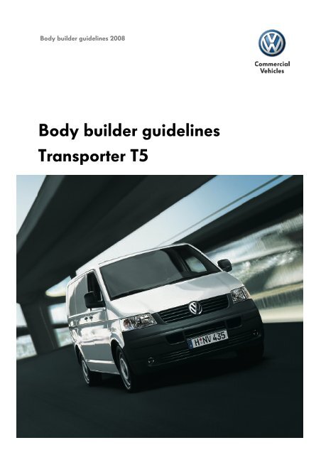
<strong>Body</strong> <strong>builder</strong> <strong>guidelines</strong> 2008<br />
<strong>Body</strong> <strong>builder</strong> <strong>guidelines</strong><br />
<strong>Transporter</strong> <strong>T5</strong>
<strong>Body</strong> assembly <strong>guidelines</strong> Volkswagen Nutzfahrzeuge<br />
The <strong>Transporter</strong> <strong>T5</strong><br />
The following pages contain technical <strong>guidelines</strong> for custom body manufacturers/ coachwork<br />
specialists for construction and assembly of custom body-related parts and conversions.<br />
The body assembly <strong>guidelines</strong> should be strictly adhered to if modifications are made with the<br />
intention of doing so.<br />
Included in the Volkswagen body assembly <strong>guidelines</strong> are also the body dimension plans for our<br />
commercial vehicles Crafter, <strong>Transporter</strong> T4 and <strong>T5</strong>, Caddy and LT. These can be installed in 3<br />
formats (TIF, DXF, IGES) for CAD programs and as PDF files.<br />
Advice: If further technical queries about the series production vehicle arise over and beyond these<br />
<strong>guidelines</strong>, please contact your local conversion expert at your importer.<br />
Volkswagen Nutzfahrzeuge<br />
Brieffach 2965/5<br />
Postfach 21 05 80<br />
D - 30405 Hannover<br />
Fax. +49 (0)511 / 7 98 - 85 00<br />
Online contact: http://www.vwn-aufbaurichtlinien.de/de/kontaktformular<br />
Note: Subject to errors and technical amendments. The electronic version of the body <strong>guidelines</strong> is the<br />
decisive source of up-to-date data on body <strong>guidelines</strong> http://www.vwn-aufbaurichtlinien.de<br />
Data status September 2008
The body assembly <strong>guidelines</strong> contain technical <strong>guidelines</strong> for custom body manufacturers/coachwork specialists for<br />
construction and assembly of custom body-related parts and conversions in and on the Volkswagen <strong>Transporter</strong>.<br />
The body assembly <strong>guidelines</strong> should be strictly adhered to if modifications are made with the intention of doing so.<br />
For all modifications, make absolutely sure that the functional safety of all components of the running gear, the body and<br />
the electrical system is guaranteed. These modifications should only be carried out by trained specialists in accordance<br />
with recognised trade skills from the motor vehicle industry.<br />
The prerequisite for modifications to used vehicles is: The vehicle should be in a generally good state of repair, i.e.<br />
structural parts such as longitudinal members and cross members, pillars, etc. should not be corroded to the extent that<br />
sacrifices have to be made in structural rigidity.<br />
Modifications that affect the vehicle s general certificate of roadworthiness must be presented to an authorised testing<br />
centre for validation. It is recommended that such modifications are agreed upon in advance with the relevant authority.<br />
For inquiries about planned modifications, please attach two sets of plans with the full scope of work, including all weight,<br />
centre of gravity and dimensional figures, from which the exact means of attachment of the body to the chassis can be<br />
gleaned. Furthermore, please inform us about the conditions in which the modified vehicle will operate.<br />
Providing the customisation or conversion measures to the interior or exterior of the vehicle meet these <strong>guidelines</strong>, there<br />
will be no need to obtain a special permit from Volkswagen AG for submission to the relevant authority.<br />
The relevant work safety regulations should be observed.<br />
Note: Subject to errors and technical amendments. The electronic version of the body <strong>guidelines</strong> is the decisive source of up-to-date data on body <strong>guidelines</strong> (online body<br />
<strong>guidelines</strong>). Data status August 2007<br />
1
For the items supplied by the custom body manufacturer/coachwork specialist,<br />
the associated conditions of warranty apply. Warranty claims associated with<br />
complaints to the items supplied can therefore not be made within the scope of<br />
warranty for the Volkswagen <strong>Transporter</strong>.<br />
The responsibility for design and assembly of custom body parts and conversions for the interior or exterior of the vehicle,<br />
and any consequent defects to the base vehicles caused as a result, is placed wholly on the custom body<br />
manufacturer/coachwork specialist. With a view to the diversity of modifications and different end uses, the notes given by<br />
Volkswagen AG herein are restricted to the provision that they have not carried out any trials on the modified vehicles<br />
themselves. Modifications can result in changes to the properties of the vehicle.<br />
For reasons of liability, it is therefore necessary for the custom body<br />
manufacturer/coachwork specialist to offer, in writing, the following notice to its<br />
customers:<br />
Due to modifications to your Volkswagen <strong>Transporter</strong>, the properties of the<br />
vehicle have been affected.<br />
Please understand that Volkswagen AG can accept no liability for any negative<br />
effects that may have been brought about by modifications to the vehicle.<br />
If there is uncertainty as to whether a defect or damage has been caused by<br />
Volkswagen or the custom/converted body parts from the custom body manufacturer, an assumption will be made in the<br />
relationship between Volkswagen and the custom body manufacturer that the custom/converted body<br />
parts were the cause.<br />
Volkswagen AG reserves the right in special circumstances to demand proof of<br />
the information provided by the customer.<br />
Legal entitlement to a permit for body customisation measures is fundamentally<br />
not granted, even if a permit was granted in the past.<br />
For modifications, all valid legal motor vehicle technology regulations<br />
and <strong>guidelines</strong> (underride protection, lighting equipment, etc.) and other<br />
relevant regulations, e.g. with regards to environmental issues and<br />
vehicle safety, must be observed.<br />
*In place of modifications , the precise work measures carried out can also be<br />
specified here, e.g. installation of camping equipment , modification of<br />
wheelbase , box body .<br />
Note: Subject to errors and technical amendments. The electronic version of the body <strong>guidelines</strong> is the decisive source of up-to-date data on body <strong>guidelines</strong> (online body<br />
<strong>guidelines</strong>). Data status August 2007<br />
1
• Two wheelbases<br />
• Four weight categories of 2600 kg, 2800 kg, 3000 kg and 3200 kg.<br />
• Good percentage of effective space<br />
• Loading width between wheelbases of 124 cm, size of pallet<br />
• Low, level cargo bed of 56 cm in height<br />
• Rigid frame and smooth upper strap for easy body assembly<br />
• Independent front and rear suspension<br />
• Powerful and economic range of engines<br />
• Excellent drag coefficient of 0.33 on panel van and Kombi<br />
• High vehicle safety<br />
• Towing capacity up to 2,500 kg<br />
• 4motion available on all models<br />
• Low maintenance requirement<br />
1
Note: Subject to errors and technical amendments. The electronic version of the body <strong>guidelines</strong> is the decisive source of up-to-date data on body <strong>guidelines</strong> (online body<br />
<strong>guidelines</strong>). Data status August 2007<br />
2
<strong>Body</strong> assembly <strong>guidelines</strong> Volkswagen Nutzfahrzeuge<br />
The <strong>Transporter</strong> <strong>T5</strong><br />
The following pages contain technical <strong>guidelines</strong> for custom body manufacturers/ coachwork<br />
specialists for construction and assembly of custom body-related parts and conversions.<br />
The body assembly <strong>guidelines</strong> should be strictly adhered to if modifications are made with the<br />
intention of doing so.<br />
Included in the Volkswagen body assembly <strong>guidelines</strong> are also the body dimension plans for our<br />
commercial vehicles Crafter, <strong>Transporter</strong> T4 and <strong>T5</strong>, Caddy and LT. These can be installed in 3<br />
formats (TIF, DXF, IGES) for CAD programs and as PDF files.<br />
Advice: If further technical queries about the series production vehicle arise over and beyond these<br />
<strong>guidelines</strong>, please contact your local conversion expert at your importer.<br />
Volkswagen Nutzfahrzeuge<br />
Brieffach 2965/5<br />
Postfach 21 05 80<br />
D - 30405 Hannover<br />
Fax. +49 (0)511 / 7 98 - 85 00<br />
Online contact: http://www.vwn-aufbaurichtlinien.de/de/kontaktformular<br />
Note: Subject to errors and technical amendments. The electronic version of the body <strong>guidelines</strong> is the<br />
decisive source of up-to-date data on body <strong>guidelines</strong> http://www.vwn-aufbaurichtlinien.de<br />
Data status September 2008
Volkswagen AG offers front-wheel drive vehicle, such as panel van, Kombi, drop-side, chassis with cab, double cab and<br />
chassis with double cab, in the following weight categories: Reduced load capacity (PR no. 0WL). Standard load capacity<br />
(PR no. 0WM) and increased load capacity (PR no. 0J3) 4motion vehicles are only offered with standard load capacity<br />
(PR no. 0WM) and increased load capacity (PR no. 0WQ). For panel vans and Kombis, a maxi version with 3.2 t (PR no.<br />
0WR) is offered.<br />
Permissible weights, unladen weights<br />
The weight entries in the technical data refer to the series production vehicle with basic equipment. Weight tolerances of<br />
+5 % in production are permissible in accordance with DIN 70020 and, if necessary, allowances should be made<br />
respectively. If special equipment is installed, the unladen weight will be increased. The final unladen weight of the<br />
complete vehicle should be checked on a weighbridge or similar.<br />
4-cylinder turbo-diesel 1.9 ltr. 77 kW/63 kW<br />
5-cylinder turbo-diesel 2.5 ltr. 96 kW/128 kW<br />
6-cylinder petrol engine 3.2 ltr. 170 kW<br />
4-cylinder petrol engine 2.0 ltr. 85 kW<br />
Designation PR No. Wheelbase<br />
mm<br />
Max.<br />
perm.<br />
weight kg<br />
Perm.<br />
axle load<br />
front kg<br />
Perm.<br />
axle load<br />
rear kg<br />
Unladen<br />
weight with<br />
driver<br />
Of which<br />
on front<br />
axle<br />
Of which<br />
on rear<br />
axle<br />
Panel van 0WL 3000 2600 1400 1400 1800 1123 677 800<br />
Panel van, lowered 0WM<br />
suspension Runing gear +2MD<br />
load<br />
capacity<br />
kg<br />
3000 2800 1450 1500 1800 1123 677 1000<br />
Panel van 0WM 3000 2800 1450 1550 1800 1123 677 1000<br />
Panel van 0WQ 3000 3000 1500 1625 1800 1123 677 1200<br />
Panel van 0WR 3000 3200 1) 1630 1720 1809 1128 681 1391<br />
Panel van, medium high<br />
roof, lowered<br />
suspension Running<br />
gear<br />
Panel van, medium high<br />
roof<br />
Panel van, medium high<br />
roof<br />
Panel van, lowered<br />
suspension<br />
0WM 3000 2800 1450 1500 1830 1136 694 970<br />
0WM<br />
+2MD<br />
3000 2800 1450 1550 1830 1136 694 970<br />
0WQ 3000 3000 1500 1625 1830 1136 694 1170<br />
0WM<br />
+2MD<br />
3400 2800 1550 1500 1830 1148 682 970<br />
Panel van 0WM 3400 2800 1550 1550 1830 1148 682 970<br />
Panel van 0WQ 3400 3000 1575 1625 1830 1148 682 1170<br />
Panel van 0WR 3400 3200 1) 1650 1720 1839 1153 686 1361<br />
Panel van, medium high<br />
roof, lowered<br />
suspension<br />
Panel van, medium high<br />
roof<br />
0WM<br />
+2MD<br />
3400 2800 1550 1500 1860 1157 703 940<br />
0WM 3400 2800 1550 1550 1860 1157 703 940<br />
1
Panel van, medium high<br />
roof<br />
Panel van, lowered<br />
suspension<br />
Panel van, high roof,<br />
lowered suspension<br />
0WQ 3400 3000 1575 1625 1860 1157 703 1140<br />
0WR 3400 3200 1) 1650 1720 1869 1162 707 1331<br />
0WM<br />
+2MD<br />
3400 2800 1550 1500 1880 1162 718 920<br />
Panel van, high roof 0WM 3400 2800 1550 1550 1880 1162 718 920<br />
Panel van, high roof 0WQ 3400 3000 1575 1625 1880 1162 718 1120<br />
Panel van, high roof 0WR 3400 3200 1) 1650 1720 1889 1167 722 1311<br />
Kombi 0WL 3000 2600 1480 1350 1865 2) 1157 708 735<br />
Kombi, lowered<br />
suspension<br />
0WM<br />
+2MD<br />
3000 2800 1480 1400 1865 2) 1157 708 935<br />
Kombi 0WM 3000 2800 1480 1460 1865 2) 1157 708 935<br />
Kombi 0WQ 3000 3000 1480 1550 1865 2) 1157 708 1135<br />
Kombi 0WR 3000 3200 1) 1640 1720 1874 2) 1162 712 1326<br />
Kombi, medium high<br />
roof, lowered<br />
suspension<br />
Kombi, medium roof<br />
0WM 3000 2800 1480 1400 1895 2) 1170 725 905<br />
0WM<br />
+2MD<br />
3000 2800 1480 1460 1895 2) 1170 725 905<br />
Kombi, medium roo 0WQ 3000 3000 1480 1550 1895 2) 1170 725 1105<br />
Kombi, lowered<br />
suspension<br />
0WM<br />
+2MD<br />
3400 2800 1550 1400 1905 2) 1172 733 895<br />
Kombi 0WM 3400 2800 1550 1460 1905 2) 1172 733 895<br />
Kombi 0WQ 3400 3000 1550 1550 1905 2) 1172 733 1095<br />
Kombi 0WR 3400 3200 1) 1640 1720 1914 2) 1177 737 1286<br />
Kombi, medium high<br />
roof, lowered<br />
suspension<br />
0WM<br />
+2MD<br />
3400 2800 1550 1400 1935 2) 1181 754 865<br />
Kombi, medium roof 0WM 3400 2800 1550 1460 1935 2) 1181 754 865<br />
Kombi, medium roof 0WQ 3400 3000 1550 1550 1935 2) 1181 754 1065<br />
Kombi, medium roof 0WR 3400 3200 1) 1640 1720 1944 2) 1186 758<br />
Kombi, high roof,<br />
lowered suspension<br />
0WM<br />
+2MD<br />
3400 2800 1550 1400 1955 2) 1186 769 845<br />
Kombi, high roof 0WM 3400 2800 1550 1460 1955 2) 1186 769 845<br />
Kombi, high roof 0WQ 3400 3000 1550 1550 1955 2) 1186 769 1045<br />
Kombi, high roof 0WR 3400 3200 1) 1640 1720 1964 2) 1191 773 1236<br />
Drop-side/deep bed,<br />
drop-side<br />
Drop-side/deep bed,<br />
drop-side<br />
Drop-side/deep bed,<br />
drop-side<br />
Drop-side/deep bed,<br />
drop-side<br />
0WM 3000 2800 1350 1580 1740 1150 590 1060<br />
0WQ 3000 3000 1450 1680 1740 1150 590 1260<br />
0WM 3400 2800 1390 1580 1800 1197 603 1000<br />
0WQ 3400 3000 1490 1680 1800 1197 603 1200<br />
Chassis with cab 0WM 3000 2800 1350 1580 1575 1143 432 1225<br />
Chassis with cab 0WQ 3000 3000 1450 1680 1575 1143 432 1425<br />
Chassis with cab 0WM 3400 2800 1390 1580 1615 1179 436 1185<br />
Chassis with cab 0WQ 3400 3000 1490 1680 1615 1179 436 1385<br />
2
Double cab/deep, bed<br />
drop-side<br />
Double cab/deep, bed<br />
drop-side<br />
0WM 3400 2800 1480 1630 1840 1180 660 960<br />
0WQ 3400 3000 1510 1680 1840 1180 660 1160<br />
Chassis with double cab 0WM 3400 2800 1480 1630 1690 1183 507 1110<br />
Chassis with double cab 0WQ 3400 3000 1510 1680 1690 1183 507 1310<br />
Designation PR- No. Wheelbase<br />
mm<br />
Panel van, lowered<br />
suspension<br />
0WM<br />
+2MD<br />
Max.<br />
perm.<br />
weight kg<br />
Perm.<br />
axle load<br />
front kg<br />
Perm.<br />
axle load<br />
rear kg<br />
Unladen<br />
weight with<br />
driver<br />
Of which<br />
on front<br />
axle<br />
Of which<br />
on rear<br />
axle<br />
3000 2800 1575 1500 1875 1201 674 925<br />
Panel van 0WM 3000 2800 1575 1550 1875 1201 674 925<br />
Panel van 0WQ 3000 3000 1575 1625 1875 1201 674 1125<br />
Panel van 0WR 3000 3200 1) 1650 1720 1884 1206 678 1316<br />
Panel van, medium<br />
high roof, lowered<br />
suspension<br />
Panel van, medium<br />
high roof<br />
Panel van, medium<br />
high roof<br />
Panel van, lowered<br />
suspension<br />
0WM 3000 2800 1575 1500 1905 1214 691 895<br />
0WM<br />
+2MD<br />
3000 2800 1575 1550 1905 1214 691 895<br />
load<br />
capacity<br />
kg<br />
0WQ 3000 3000 1575 1625 1905 1214 691 1095<br />
0WM<br />
+2MD<br />
3400 2800 1575 1500 1905 1226 679 895<br />
Panel van 0WM 3400 2800 1575 1550 1905 1226 679 895<br />
Panel van 0WQ 3400 3000 1575 1625 1905 1226 679 1095<br />
Panel van 0WR 3400 3200 1) 1650 1720 1914 1231 683 1286<br />
Panel van, medium<br />
high roof, lowered<br />
suspension<br />
Panel van, medium<br />
high roof<br />
Panel van, medium<br />
high roof<br />
Panel van, medium<br />
high roof<br />
Panel van, high roof,<br />
lowered suspension<br />
0WM<br />
+2MD<br />
3400 2800 1575 1500 1935 1235 700 865<br />
0WM 3400 2800 1575 1550 1935 1235 700 865<br />
0WQ 3400 3000 1575 1625 1935 1235 700 1065<br />
0WR 3400 3200 1) 1650 1720 1944 1240 704 1256<br />
0WM<br />
+2MD<br />
3400 2800 1575 1500 1955 1240 715 845<br />
Panel van, high roof 0WM 3400 2800 1575 1550 1955 1240 715 845<br />
Panel van, high roof 0WQ 3400 3000 1575 1625 1955 1240 715 1045<br />
Panel van, high roof 0WR 3400 3200 1) 1650 1720 1964 1245 719 1236<br />
Kombi<br />
tiefergelegtes Fahrw.<br />
Kombi<br />
0WM<br />
+2MD<br />
3000 2800 1575 1400 1940 2) 1235 705 860<br />
Kombi 0WM 3000 2800 1575 1460 1940 2) 1235 705 860<br />
3
Kombi 0WQ 3000 3000 1575 1550 1940 2) 1235 705 1060<br />
Kombi, medium high<br />
roof lowered<br />
suspension<br />
0WR 3000 3200 1) 1640 1720 1949 2) 1240 709 1251<br />
Kombi, medium roof 0WM 3000 2800 1575 1400 1970 2) 1248 722 830<br />
Kombi, medium roof<br />
Kombi, lowered<br />
suspension<br />
Kombi<br />
0WM<br />
+2MD<br />
3000 2800 1575 1460 1970 2) 1248 722 830<br />
0WQ 3000 3000 1575 1550 1970 2) 1248 722 1030<br />
0WM<br />
+2MD<br />
3400 2800 1575 1400 1980 2) 1250 730 820<br />
Kombi 0WM 3400 2800 1575 1460 1980 2) 1250 730 820<br />
Kombi 0WQ 3400 3000 1575 1550 1980 2) 1250 730 1020<br />
Kombi, medium high<br />
roof, lowered<br />
suspension<br />
Kombi, medium roof<br />
0WR 3400 3200 1) 1710 1720 1989 2) 1255 734 1211<br />
0WM<br />
+2MD<br />
3400 2800 1575 1400 2010 2) 1259 751 790<br />
Kombi, medium roof 0WM 3400 2800 1575 1460 2010 2) 1259 751 790<br />
Kombi, medium roof 0WQ 3400 3000 1575 1550 2010 2) 1259 751 990<br />
Kombi, high roof,<br />
lowered suspension<br />
Kombi, high roof<br />
0WR 3400 3200 1) 1710 1720 2019 2) 1264 755 1181<br />
0WM<br />
+2MD<br />
3400 2800 1575 1400 2030 2) 1264 766 770<br />
Kombi, high roof 0WM 3400 2800 1575 1460 2030 2) 1264 766 770<br />
Kombi, high roof 0WQ 3400 3000 1575 1550 2030 2) 1264 766 970<br />
Drop-side/deep bed<br />
drop-side<br />
Drop-side/deep bed<br />
drop-side<br />
Drop-side/deep bed<br />
drop-side<br />
Drop-side/deep bed<br />
drop-side<br />
0WR 3400 3200 1) 1710 1720 2039 2) 1269 770 1161<br />
0WM 3000 2800 1430 1580 1815 1228 587 985<br />
0WQ 3000 3000 1530 1680 1815 1228 587 1185<br />
0WM 3400 2800 1480 1580 1875 1275 600 925<br />
Chassis with cab 0WQ 3400 3000 1575 1680 1875 1275 600 1125<br />
Chassis with cab 0WM 3000 2800 1430 1580 1650 1221 429 1150<br />
Chassis with cab 0WQ 3000 3000 1530 1680 1650 1221 429 1350<br />
Chassis with cab 0WM 3400 2800 1480 1580 1690 1257 433 1110<br />
Double cab/deep bed<br />
drop-side<br />
Double cab/deep bed<br />
drop-side<br />
Chassis with double<br />
cab<br />
Chassis with double<br />
cab<br />
Panel van, lowered<br />
suspension<br />
0WQ 3400 3000 1575 1680 1690 1257 433 1310<br />
0WM 3400 2800 1575 1630 1915 1258 657 885<br />
0WQ 3400 3000 1575 1680 1915 1258 657 1085<br />
0WM 3400 2800 1575 1630 1765 1261 504 1035<br />
0WQ 3400 3000 1575 1680 1765 1261 504 1235<br />
4
Designation PR- No. Wheelbase<br />
mm<br />
Panel van, lowered<br />
suspension<br />
0WM<br />
+2MD<br />
Max.<br />
perm.<br />
weight kg<br />
Perm.<br />
axle load<br />
front kg<br />
Perm.<br />
axle load<br />
rear kg<br />
Unladen<br />
weight with<br />
driver<br />
Of which<br />
on front<br />
axle<br />
Of which<br />
on rear<br />
axle<br />
3000 2800 1575 1500 1900 1218 682 900<br />
Panel van 0WM 3000 2800 1575 1550 1900 1218 682 900<br />
Panel van 0WQ 3000 3000 1575 1625 1900 1218 682 1100<br />
Panel van, medium<br />
high roof, lowered<br />
suspension<br />
Panel van, medium<br />
high roof<br />
Panel van, medium<br />
high roof<br />
Panel van, lowered<br />
suspension<br />
0WM 3000 2800 1575 1500 1930 1231 699 870<br />
0WM<br />
+2MD<br />
3000 2800 1575 1550 1930 1231 699 870<br />
load<br />
capacity<br />
kg<br />
0WQ 3000 3000 1575 1625 1930 1231 699 1070<br />
0WM<br />
+2MD<br />
3400 2800 1575 1500 1930 1243 687 870<br />
Panel van 0WM 3400 2800 1575 1550 1930 1243 687 870<br />
Panel van 0WQ 3400 3000 1575 1625 1930 1243 687 1070<br />
Panel van<br />
Panel van, medium<br />
high roof, lowered<br />
suspenion<br />
Panel van, medium,<br />
high roof<br />
Panel van, medium<br />
high roof<br />
Panel van, medium<br />
high roof, lowered<br />
suspension<br />
0WM<br />
+2MD<br />
3400 2800 1575 1500 1960 1252 708 840<br />
0WM 3400 2800 1575 1550 1960 1252 708 840<br />
0WQ 3400 3000 1575 1625 1960 1252 708 1040<br />
0WM<br />
+2MD<br />
3400 2800 1575 1500 1980 1257 723 820<br />
0WM 3400 2800 1575 1550 1980 1257 723 820<br />
Panel van, high roof 0WQ 3400 3000 1575 1625 1980 1257 723 1020<br />
Kombi, lowered<br />
suspension<br />
0WM<br />
+2MD<br />
3000 2800 1575 1400 1965 2) 1252 713 835<br />
Kombi 0WM 3000 2800 1575 1460 1965 2) 1252 713 835<br />
Kombi 0WQ 3000 3000 1575 1550 1965 2) 1252 713 1035<br />
Kombi, medium high<br />
roof, lowered<br />
suspension<br />
Kombi, medium roof<br />
0WM 3000 2800 1575 1400 1995 2) 1265 730 805<br />
0WM<br />
+2MD<br />
3000 2800 1575 1460 1995 2) 1265 730 805<br />
Kombi, medium roof 0WQ 3000 3000 1575 1550 1995 2) 1265 730 1005<br />
Kombi, lowered<br />
suspension<br />
0WM<br />
+2MD<br />
3400 2800 1575 1400 2005 2) 1267 738 795<br />
Kombi 0WM 3400 2800 1575 1460 2005 2) 1267 738 795<br />
5
Kombi 0WQ 3400 3000 1575 1550 2005 2) 1267 738 995<br />
Kombi, medium high<br />
roof lowered<br />
suspension<br />
0WM<br />
+2MD<br />
3400 2800 1575 1400 2035 2) 1276 759 765<br />
Kombi, medium roof 0WM 3400 2800 1575 1460 2035 2) 1276 759 765<br />
Kombi, medium roof 0WQ 3400 3000 1575 1550 2035 2) 1276 759 965<br />
Kombi, high roof,<br />
lowered suspension<br />
0WM<br />
+2MD<br />
3400 2800 1575 1400 2055 2) 1281 774 745<br />
Kombi, high roof 0WM 3400 2800 1575 1460 2055 2) 1281 774 745<br />
Kombi, high roof 0WQ 3400 3000 1575 1550 2055 2) 1281 774 945<br />
Drop-side/deep bed<br />
drop-side<br />
Drop-side/deep bed<br />
drop-side<br />
Drop-side/deep bed<br />
drop-side<br />
Drop-side/deep bed<br />
drop-side<br />
0WM 3000 2800 1430 1580 1840 1245 595 960<br />
0WQ 3000 3000 1530 1680 1840 1245 595 1160<br />
0WM 3400 2800 1480 1580 1900 1292 608 900<br />
0WQ 3400 3000 1575 1680 1900 1292 608 1100<br />
Chassis with cab 0WM 3000 2800 1430 1580 1675 1238 437 1125<br />
Chassis with cab 0WQ 3000 3000 1530 1680 1675 1238 437 1325<br />
Chassis with cab 0WM 3400 2800 1480 1580 1715 1274 441 1085<br />
Chassis with cab 0WQ 3400 3000 1575 1680 1715 1274 441 1285<br />
Double cab/deep bed<br />
drop-side<br />
Double cab/deep bed<br />
drop-side<br />
Chassis with double<br />
cab<br />
Chassis with double<br />
cab<br />
0WM 3400 2800 1575 1630 1940 1275 665 860<br />
0WQ 3400 3000 1575 1680 1940 1275 665 1060<br />
0WM 3400 2800 1575 1630 1790 1278 512 1010<br />
0WQ 3400 3000 1575 1680 1790 1278 512 1210<br />
Panel van 0WL 3000 2600 1400 1400 1785 1107 678 815<br />
Panel van, lowered suspension, Running gear<br />
0WN<br />
+2MD<br />
3000 2850 1450 1500 1785 1107 678 1065<br />
Panel van 0WN 3000 2850 1450 1550 1785 1107 678 1065<br />
Panel van, medium high roof, lowered suspension<br />
Running gear<br />
0WN<br />
+2MD<br />
3000 2850 1450 1500 1815 1120 695 1035<br />
Panel van, medium high roof 0WN 3000 2850 1450 1550 1815 1120 695 1035<br />
Panel van, lowered suspension<br />
0WN<br />
+2MD<br />
3400 2850 1550 1500 1815 1132 683 1035<br />
6
Panel van 0WN 3400 2850 1550 1550 1815 1132 683 1035<br />
Panel van, medium high roof, lowered suspension<br />
0WN<br />
+2MD<br />
3400 2850 1550 1500 1845 1141 704 1005<br />
Panel van, medium high roof 0WN 3400 2850 1550 1550 1845 1141 704 1005<br />
Panel van, high roof, lowered suspension<br />
0WN<br />
+2MD<br />
3400 2850 1550 1500 1865 1146 719 985<br />
Panel van, high roof 0WN 3400 2850 1550 1550 1865 1146 719 985<br />
Kombi 0WL 3000 2600 1480 1350 1850<br />
2)<br />
Kombi, lowered suspension<br />
0WN<br />
+2MD<br />
3000 2850 1575 1400 1850<br />
2)<br />
Kombi 0WN 3000 2850 1575 1460 1850<br />
2)<br />
Kombi, medium high roof, lowered suspension<br />
0WN<br />
+2MD<br />
3000 2850 1575 1400 1880<br />
2)<br />
Kombi, medium roof 0WN 3000 2850 1575 1460 1880<br />
2)<br />
Kombi, lowered suspension<br />
0WN<br />
+2MD<br />
3400 2850 1575 1400 1890<br />
2)<br />
Kombi 0WN 3400 2850 1575 1460 1890<br />
2)<br />
Kombi<br />
Kombi<br />
Kombi, medium high roof, lowered suspension<br />
0WN<br />
+2MD<br />
3400 2850 1575 1400 1920<br />
2)<br />
Kombi, medium roof 0WN 3400 2850 1575 1460 1920<br />
2)<br />
Kombi, high roof, lowered suspension<br />
0WN<br />
+2MD<br />
3400 2850 1575 1400 1940<br />
2)<br />
Kombi, high roof 0WN 3400 2850 1575 1460 1940<br />
2)<br />
1141 709 750<br />
1141 709 1000<br />
1141 709 1000<br />
1154 726 970<br />
1154 726 970<br />
1156 734 960<br />
1156 734 960<br />
1165 755 930<br />
1165 755930<br />
1170 770 910<br />
1170 770 910<br />
Drop-side/deep bed drop-side 0WN 3000 2850 1430 1580 1725 1134 591 1125<br />
Drop-side/deep bed drop-side 0WN 3400 2850 1480 1580 1785 1181 604 1065<br />
Chassis with cab 0WN 3000 2850 1430 1580 1560 1127 433 1290<br />
7
Chassis with cab 0WN 3400 2850 1480 1580 1600 1163 437 1250<br />
Chassis with cab 0WN 3400 2850 1575 1630 1825 1164 661 1025<br />
Chassis with double cab 0WN 3400 2850 1575 1630 1675 1167 508 1175<br />
1) Max. perm. weight 3,200 kg only for vehicles with 4 cyl. 77 kW and 5 cyl. 96 kW TDI<br />
2) Unladen weight with side trim in passenger/load compartment. Side trim can be deselected with PR no. 5DA.<br />
Unladen weights inc. driver and without seats in passenger compartment. On vehicles with permanent four-wheel drive,<br />
4motion, unladen weight is increased by 100 kg (front axle=25 kg, rear axle=75 kg). The load capacity is reduced<br />
respectively. The maximum permissible weight remains unchanged.<br />
Note: Subject to errors and technical amendments. The electronic version of the body <strong>guidelines</strong> is the decisive source of up-to-date data on body <strong>guidelines</strong> (online body<br />
<strong>guidelines</strong>). Data status January 2008<br />
8
Under no circumstances should<br />
be exceeded.<br />
• max. perm. weight<br />
• perm. front axle load<br />
• perm. rear axle load<br />
When drawing up plans for custom body parts/conversions, ensure that onesided<br />
weight distribution is avoided, in particular with permanently installed<br />
custom body parts. If this cannot be avoided, the one-sided load should not<br />
result in a greater difference between the wheel pairs of max. 4%.<br />
Perm. axle load 1.680 kg<br />
Theor. wheel load left/right 840 kg/840 kg<br />
4% of this wheel load 34 kg<br />
Perm. wheel load distr. left/right 806 kg/874 kg<br />
To guarantee an acceptable level of steerability of the vehicle and to assure<br />
satisfactory road handling in all load conditions, the minimum front axle load<br />
should be 1,050 kg.<br />
1
Note: Subject to errors and technical amendments. The electronic version of the body <strong>guidelines</strong> is the decisive source of up-to-date data on body <strong>guidelines</strong> (online body<br />
<strong>guidelines</strong>). Data status August 2007<br />
2
Note: Subject to errors and technical amendments. The electronic version of the body <strong>guidelines</strong> is the decisive source of up-to-date data on body <strong>guidelines</strong> (online body<br />
<strong>guidelines</strong>). Data status August 2007<br />
4
Note: Subject to errors and technical amendments. The electronic version of the body <strong>guidelines</strong> is the decisive source of up-to-date data on body <strong>guidelines</strong> (online body<br />
<strong>guidelines</strong>). Data status August 2007<br />
3
Note: Subject to errors and technical amendments. The electronic version of the body <strong>guidelines</strong> is the decisive source of up-to-date data on body <strong>guidelines</strong> (online body<br />
<strong>guidelines</strong>). Data status August 2007<br />
1
The dimensions of the vehicle chassis can be gleaned from the diagrams. To aid your conversion plans, the chassis<br />
dimensions are given in a scale of 1:20 and 1:10.<br />
If uprated springs, comfort springs or tyre sizes that deviate from the standard specifications are fitted, the vehicle and<br />
frame heights can change considerably from the base level. If this equipment is to be used, we ask you to please take this<br />
fact into consideration.<br />
Important note<br />
• The minimum distance between cab and body should be 30 mm.<br />
• The rear overhang of the custom body should not exceed 43% of the wheelbase.<br />
Due to this restriction in length, the following custom body outer lengths should not be exceeded:<br />
Wheelbase Standard body length, inner Wheelbase Standard body length, inner<br />
Chassis with cab 3.000 mm 2.539 mm 2.692 mm<br />
Chassis with cab 3.400 mm 2.939 mm 3.264 mm<br />
Chassis with double cab 3.400 mm 2.169 mm 2.212 mm<br />
The outer width of the cab is 1,902 mm. If standard type exterior mirrors are used, the body width should not exceed 2,200<br />
mm.<br />
Note: Subject to errors and technical amendments. The electronic version of the body <strong>guidelines</strong> is the decisive source of up-to-date data on body <strong>guidelines</strong> (online body<br />
<strong>guidelines</strong>). Data status August 2007<br />
1
The frame is a hollow profile construction made from pressed panel parts. In order to ensure correct provision is made to<br />
secure the custom bodies in place, the following precautionary measures have been taken with regards to the<br />
construction.<br />
Consoles have been welded to the longitudinal members, which serve as a means<br />
of securing the custom bodies. Each console features a drilling of D=11.5 mm.<br />
The attachment of body to vehicle frame should always be carried out using all consoles. The bolted connection to the<br />
consoles should always be a flush bonded one.<br />
The gap between the consoles above the vehicle frame should be padded out.<br />
Note: Subject to errors and technical amendments. The electronic version of the body <strong>guidelines</strong> is the decisive source of up-to-date data on body <strong>guidelines</strong> (online body<br />
<strong>guidelines</strong>). Data status August 2007<br />
1
<strong>Body</strong> assembly <strong>guidelines</strong> Volkswagen Nutzfahrzeuge<br />
The <strong>Transporter</strong> <strong>T5</strong><br />
The following pages contain technical <strong>guidelines</strong> for custom body manufacturers/ coachwork<br />
specialists for construction and assembly of custom body-related parts and conversions.<br />
The body assembly <strong>guidelines</strong> should be strictly adhered to if modifications are made with the<br />
intention of doing so.<br />
Included in the Volkswagen body assembly <strong>guidelines</strong> are also the body dimension plans for our<br />
commercial vehicles Crafter, <strong>Transporter</strong> T4 and <strong>T5</strong>, Caddy and LT. These can be installed in 3<br />
formats (TIF, DXF, IGES) for CAD programs and as PDF files.<br />
Advice: If further technical queries about the series production vehicle arise over and beyond these<br />
<strong>guidelines</strong>, please contact your local conversion expert at your importer.<br />
Volkswagen Nutzfahrzeuge<br />
Brieffach 2965/5<br />
Postfach 21 05 80<br />
D - 30405 Hannover<br />
Fax. +49 (0)511 / 7 98 - 85 00<br />
Online contact: http://www.vwn-aufbaurichtlinien.de/de/kontaktformular<br />
Note: Subject to errors and technical amendments. The electronic version of the body <strong>guidelines</strong> is the<br />
decisive source of up-to-date data on body <strong>guidelines</strong> http://www.vwn-aufbaurichtlinien.de<br />
Data status September 2008
Roof carriers<br />
Roof loads increase the centre point of gravity on the vehicle and lead to high dynamic shifts in axle load and tilting of the<br />
vehicle on uneven surfaces and in corners. Road handling is considerably impaired. For this reason, roof loads should be<br />
avoided if at all possible.<br />
Depending on the load distribution, at least 2 basic carriers are needed and these should be placed as close to the pillar<br />
area as possible.<br />
On panel vans and Kombi versions, there are 4 securing points on each side of the roof. Double cab has 2 securing points<br />
each side and drop-side 1 securing point each side.<br />
Vehicles with normal roof 100 kg<br />
Double cab 75 kg<br />
Chassis cab 50 kg<br />
Pop-up roof 50 kg<br />
Rear luggage carriers/rear ladders<br />
The rear luggage carrier and rear ladder should be of a design structure that, when fitted, does not allow static or dynamic<br />
loads to affect the shock absorbers.<br />
The tailgate may be subjected to a max. load of 75 kg.<br />
Drop-side with tarpaulin and frame (fitted in factory)<br />
With the exception of the tarpaulin, the frame bracing should not be placed under any further loads, such as ladders for<br />
example.<br />
Note: Subject to errors and technical amendments. The electronic version of the body <strong>guidelines</strong> is the decisive source of up-to-date data on body <strong>guidelines</strong> (online body<br />
<strong>guidelines</strong>). Data status August 2007<br />
1
In onboard electrical systems, electrical disturbances can be caused by individual consumers. At Volkswagen AG, the<br />
electronic components installed in the factory are checked in the vehicle for their electromagnetic compatibility.<br />
If retrofitting electrical or electronic systems, their electromagnetic compatibility should also be checked.<br />
The following industrial standards provide the necessary details:<br />
• DIN 40839<br />
• DIN 57879, part 3<br />
• VDE 0879, part 3<br />
• VWTL 965<br />
• VWTL 82066<br />
• VWTL 82166<br />
• VWTL 82366<br />
Furthermore, EMC guideline EC 72/245 version 95/54 EC should be observed<br />
Note: Subject to errors and technical amendments. The electronic version of the body <strong>guidelines</strong> is the decisive source of up-to-date data on body <strong>guidelines</strong> (online body<br />
<strong>guidelines</strong>). Data status August 2007<br />
1
An operating permit has been granted for the vehicle braking systems. This permit becomes void if any changes to the<br />
brake system are made.<br />
Modifications to brake system are not permitted!<br />
Note: Subject to errors and technical amendments. The electronic version of the body <strong>guidelines</strong> is the decisive source of up-to-date data on body <strong>guidelines</strong> (online body<br />
<strong>guidelines</strong>). Data status August 2007<br />
1
The load-dependent brake pressure limiter is set in the factory via a spring mechanism to the unladen weight of the<br />
vehicle. This setting should not normally be adjusted, even following assembly of a custom body on the chassis.<br />
In particular cases, e.g. retrofitting of heavy duty springs, unusually lightweight body construction, this setting of the brake<br />
pressure limiter can be altered.<br />
Pressure control and adjustment should be carried out by a Volkswagen commercial vehicle dealership.<br />
Note: Subject to errors and technical amendments. The electronic version of the body <strong>guidelines</strong> is the decisive source of up-to-date data on body <strong>guidelines</strong> (online body<br />
<strong>guidelines</strong>). Data status August 2007<br />
1
Connect pressure gauge to rear wheel cylinder. To do this, unscrew bleed valve. Press brake pedal hard until input<br />
pressure (see data plate of brake pressure limiter device) is reached and then adjust output pressure. Once checked,<br />
bleed the brake system. Tighten bleed screw to MA = 4.9+1 Nm.<br />
General note<br />
We recommend that custom body manufacturers/coachwork specialists include relevant service details and, if necessary,<br />
operating instructions for their scope of equipment.<br />
Note: Subject to errors and technical amendments. The electronic version of the body <strong>guidelines</strong> is the decisive source of up-to-date data on body <strong>guidelines</strong> (online body<br />
<strong>guidelines</strong>). Data status August 2007<br />
1
The ABS requires an identical signal from the front and rear axle (active signal, detection of circumference to number of<br />
teeth).<br />
The ABS functions and settings have been checked and authorised for use only with series production components, rear<br />
axle brake, wheels and tyres.<br />
For use of different wheels/tyres, for example on the front axle, a new wheel bearing unit must be installed (with speed<br />
sender Z = see below).<br />
The number of teeth is calculated as follows:<br />
Z = (f x U) / (2 x v)<br />
Z = No. of teeth<br />
f = Edge frequency (in Hz)<br />
U = Circumference (in mm)<br />
v = Speed (in mm/s)<br />
The basis for the ABS regulator is a circumference of 1990 mm and 48 teeth (96 for evaluation of rise and fall edge);<br />
which equates to an edge frequency of 1340 Hz at 100 km/h.<br />
Note: Subject to errors and technical amendments. The electronic version of the body <strong>guidelines</strong> is the decisive source of up-to-date data on body <strong>guidelines</strong> (online body<br />
<strong>guidelines</strong>). Data status August 2007<br />
1
Die Elektroschnittstelle bietet die Möglichkeit, bestimmte analoge Signale/ Potenziale für elektrische Sonderausstattungen<br />
zur Verfügung zu stellen, die sonst nur über CAN BUS vorliegen und nur mit sehr hohem Aufwand angeschlossen werden<br />
könnten.<br />
Der Kundenvorteil liegt darin, dass an einem sehr gut zugänglichem Ort im Fahrerraum, eine Vielfalt an elektrischen<br />
Signalen aus der Funktionselektrik abgegriffen werden kann und diese Signale je nach Kundenwunsch für individuelle<br />
Einsatzzwecke verwendet werden können.<br />
Die Nutzung dieser Signale darf nur durch autorisiertes Fachpersonal erfolgen.<br />
Durch unsachgemäße Eingriffe kann es zu Schäden am Fahrzeug sowie zum Erlöschen der Betriebserlaubnis kommen.<br />
Folgende Punkte sind unbedingt zu beachten:<br />
• diverse VDE- Richtlinien für die Auslegung und den Verbau elektrischer Leitungen und Komponenten<br />
(Kabelquerschnitte, Sicherungen, usw.),<br />
• für die Adaption an das Bordnetz dürfen nur von Volkswagen freigegebene Komponenten (Leitungen, Gehäuse,<br />
Kontakte) verwendet werden.<br />
• es werden ausschließlich VW- übliche Potenzialbezeichnungen verwendet<br />
• da angeschlossene Zusatzgeräte nicht bekannt sind, ist durch den Nutzer der Schnittstelle ein ausgeglichener<br />
Stromhaushalt zu gewährleisten<br />
• die EMV-Sicherheit für Verschaltung hinter der Schnittstelle liegt in der Verantwortung des Nutzers.<br />
• die Leitungsquerschnitte der Schnittstelle sind in der kompletten Schaltung beizubehalten, d.h. keine<br />
Querschnittsveränderungen nach der Schnittstelle<br />
• eine Einspeisung in das Bordnetz darf nur an den hierfür ausdrücklich vorgesehenen Potentialen erfolgen und ist<br />
extern nach VDE abzusichern. Bezugspotenzial ist immer das Plus-Potenzial der Starterbatterie<br />
• zusätzliche Informationen sind den Kundendienstunterlagen zu entnehmen<br />
• elektrische Leitungen, die zur Umsetzung spezieller Funktionen (z.B. Bremslichtabschaltung, Startsperre, usw.)<br />
unterbrochen werden müssen sind sicher gegen Kurzschlüsse nach Batterie + und Karosseriemasse zu<br />
schützen.<br />
• die angegebenen Potenziale beziehen sich immer auf die Fahrzeug-Karosseriemasse. Vorzugsweise zu<br />
verwenden ist der Massebolzen in der linken Sitzkiste<br />
Nr. Schnittstelle für: Potential Klemmenbezeinung<br />
1<br />
2<br />
3<br />
4<br />
Eingangsklemme direkt von<br />
Batterie<br />
Ausgangsklemme am<br />
Zündschalter<br />
(Fahrtschalter)<br />
Ausgangsklemme am<br />
Zündschalter<br />
(Fahrtschalter) für<br />
Motorweiterlauf<br />
Ausgangsklemme am<br />
Zündschalter<br />
(Fahrtschalter) für<br />
Motorweiterlauf<br />
max. Strom<br />
Entnahme<br />
B+ (Klemme 30) 30 32,0 A<br />
Klemme 15 15 2,0 A<br />
Klemme 15<br />
(Motorweiterlauf)<br />
Klemme 75 75<br />
max. Strom<br />
Einspeisung Leitungsquerschnitt<br />
nicht<br />
zulässig<br />
nicht<br />
zulässig<br />
4,0 mm2<br />
0,5 mm2<br />
15 20,0 A 25,0 A 2,5 mm2<br />
nicht<br />
zulässig<br />
200 mA 2,5 mm2<br />
5 XRA XRA* 12,0 A 1,5 mm2<br />
1
6<br />
Ausgangsklemme vom<br />
Relais X-Kontakt<br />
Ausgangsklemme am Glühund<br />
Zündanlasser<br />
(Fahrtschalter)<br />
Klemme 50 50 200 mA<br />
7 S-Kontakt Zündschloss Klemme S S-Kontakt* 2,0 A<br />
8 Geschwindigkeitssignal V V* 20 mA<br />
9<br />
10<br />
11<br />
12<br />
13<br />
Ausgangsklemme am<br />
Abblendschalter für<br />
Abblendlicht (links)<br />
Ausgangsklemme am<br />
Abblendschalter für<br />
Abblendlicht (rechts)<br />
Ausgangsklemme am<br />
Abblendschalter für<br />
Fernlicht (links)<br />
Ausgangsklemme am<br />
Abblendschalter für<br />
Fernlicht (rechts)<br />
Klemme für<br />
Nebelscheinwerfer<br />
nicht<br />
zulässig<br />
nicht<br />
zulässig<br />
nicht<br />
zulässig<br />
nicht<br />
zulässig<br />
0,5 mm2<br />
0,5 mm2<br />
0,35 mm2<br />
Klemme 56b 56b 1,0 A 12,0 A 1,5 mm2<br />
Klemme 56b 56b 1,0 A 12,0 A 1,5 mm2<br />
Klemme 56a 56a 1,0 A 12,0 A 1,5 mm2<br />
Klemme 56a 56a 1,0 A 12,0 A 1,5 mm2<br />
Klemme 55 55 3,0 A 8,0 A 1,0 mm2<br />
14 Fahrtrichtungsanzeige links Klemme 49a L (49a) 200 mA<br />
15 Fahrtrichtungsanzeige<br />
rechts<br />
16<br />
17<br />
Ausgangsschalter am<br />
Lichtschalter für Parklicht<br />
Klemme für regelbare<br />
Instrumentenbeleuchtung<br />
Klemme 49a R (49a) 200 mA<br />
Klemme 58L 58L* 1,0 A<br />
Klemme 58d 58d 2,0 A<br />
18 Klemme für Bremsleuchten Klemme 54 54 200 mA<br />
19 Rückfahrscheinwerfer RFL RFL* 1,0 A<br />
nicht<br />
zulässig<br />
nicht<br />
zulässig<br />
nicht<br />
zulässig<br />
nicht<br />
zulässig<br />
nicht<br />
zulässig<br />
nicht<br />
zulässig<br />
1,0 mm2<br />
1,0 mm2<br />
0,5 mm2<br />
0,35 mm2<br />
1,5 mm2<br />
1,0 mm2<br />
20 Handbremse Handbremskontrolle --- 10 mA<br />
nicht<br />
zulässig<br />
0,35 mm2<br />
Zusätzliche Informationen zur Elektroschnittstelle sind aus den Kundendienstunterlagen zu entnehmen.<br />
Bestellbar ist die elektrische Schnittstelle für externe Nutzung unter der PR-Nr. UF1 für alle Derivate des neuen<br />
<strong>Transporter</strong>.<br />
Note: Subject to errors and technical amendments. The electronic version of the body <strong>guidelines</strong> is the decisive source of up-to-date data on body <strong>guidelines</strong> (online body<br />
<strong>guidelines</strong>). Data status August 2007<br />
2
Diese beinhaltet die Zusatzkonsole, Kabelführung bis zum Dach bei allen Dacharten sowie den Schalter in der<br />
Zusatzkonsole.<br />
Nummern der ZSB<br />
Rundumkennleuchte (gelb)<br />
Normaldach: 7H0.941.083.D o.Z.<br />
Mittelhochdach:7H0.941.083.K o.Z.<br />
Hochdach: 7H0.941.083.L o.Z.<br />
Pritsche/DOKA:7H0.941.083.F o.Z.<br />
Koordinaten Punkt a<br />
X Y Z<br />
Toleranz<br />
Pritsche 1036,2 0 1554,8 ±0,5<br />
Doka 1036,2 0 1554,8 ±0,5<br />
Normal ohne SAD, KR 2210,0 0 1554,7 ±0,5<br />
Normal ohne SAD, LR 2210,0 0 1556,6 ±0,5<br />
Mittelhoch, KR 1530,0 0 1747,2 ±0,5<br />
Mittelhoch, LR 1530,0 0 1747,2 ±0,5<br />
Hochdach 2133,6 0 2062,6 ±0,5<br />
Note: Subject to errors and technical amendments. The electronic version of the body <strong>guidelines</strong> is the decisive source of up-to-date data on body <strong>guidelines</strong> (online body<br />
<strong>guidelines</strong>). Data status August 2007<br />
1
Diese beinhaltet die Zusatzkonsole, Kabelführung bis zum Dach bai allen Dacharten sowie den Schalter in der<br />
Zusatzkonsole.<br />
Dach PDA vom:<br />
Koordinaten Punkt a<br />
X Y Z<br />
Normal ohne SAD, KR 7H1.817.111.J TM3 29.10.2003 800,0 0 1525,0<br />
Normal ohne SAD, LR 7H3.817.111.L TM2 29.10.2003 800,0 0 1525,0<br />
Normal mit SAD, KR 7H1.817.111.K TM3 29.10.2003 800,0 0 1525,0<br />
Normal mit SAD, LR 7H3.817.111.M TM2 29.10.2003 800,0 1556,6 1525,0<br />
Mittelhoch, KR 7H1.817.111.D TM12 07.07.2003 1197,7 0 1740,0<br />
Mittelhoch, LR 7H3.817.111.D TM12 07.07.2003 1197,7 0 1740,0<br />
Hochdach 7H3.817.111.B TM17 07.07.2003 0597,5 0 2057,6<br />
1
Pos Teilenummer<br />
1 N 017 716.2<br />
2 7H0.945.713<br />
Note: Subject to errors and technical amendments. The electronic version of the body <strong>guidelines</strong> is the decisive source of up-to-date data on body <strong>guidelines</strong> (online body<br />
<strong>guidelines</strong>). Data status August 2007<br />
2
The necessary clearance for the wheels, including snow chains, must be observed. The dimensions given in the chassis<br />
diagrams is the minimum distance from the upper edge of the longitudinal member to the wheel housings.<br />
Note: Subject to errors and technical amendments. The electronic version of the body <strong>guidelines</strong> is the decisive source of up-to-date data on body <strong>guidelines</strong> (online body<br />
<strong>guidelines</strong>). Data status August 2007<br />
1
Auxiliary equipment should be attached to the frame using consoles, which are welded to the longitudinal member in the<br />
neutral zone. If a bolted connection to the frame cannot be avoided, spacer sleeves should be welded into the hollow<br />
profile members as a supplementary measure.<br />
Observe:<br />
• General notes on modifications to series prouktion vehicles (see 5.5)<br />
• Drilling in chassis frame (see 4.6)<br />
For custom parts attached to the exterior or interior, the auxiliary equipment manufacturer s regulations should be<br />
observed.<br />
Note: Subject to errors and technical amendments. The electronic version of the body <strong>guidelines</strong> is the decisive source of up-to-date data on body <strong>guidelines</strong> (online body<br />
<strong>guidelines</strong>). Data status August 2007<br />
1
Since no provision has been made for a power take-off from the gearbox, the crane can only be powered by an electric<br />
pump unit (heavy duty battery and heavy duty alternator required).<br />
Note: Subject to errors and technical amendments. The electronic version of the body <strong>guidelines</strong> is the decisive source of up-to-date data on body <strong>guidelines</strong> (online body<br />
<strong>guidelines</strong>). Data status August 2007<br />
1
Notes on installation of hydraulic tailboards<br />
Before installing a hydraulic tailboard, the permissible rear axle load and minimum front axle load should be checked by<br />
means of a calculation to determine the distribution of weight.<br />
The installation of a hydraulic tailboard on series production panel vans is not permissible without a special permit from<br />
the factory. The installation of a chair lift with a load capacity of max. 300 kg is possible.<br />
If a chassis cab is ordered, which is later to be fitted with an electro-hydraulic tailboard, we recommend the following<br />
options: Heavy duty alternator and heavy duty battery.<br />
For installation of the hydraulic tailboard, the chassis should be supplemented with an assembly frame (see note on<br />
assembly frames).<br />
Note: Subject to errors and technical amendments. The electronic version of the body <strong>guidelines</strong> is the decisive source of up-to-date data on body <strong>guidelines</strong> (online body<br />
<strong>guidelines</strong>). Data status August 2007<br />
1
Only the trailer hitches authorised by the factory should be installed for towing. As an option, the following trailer hitches<br />
can be ordered from the factory:<br />
Ball head type - order number:<br />
1D1<br />
Towing capacity max. 700 kg unbraked and 2000 - 2500 kg braked (depending on engine size) at 12% gradient rise.<br />
1D2<br />
As above but removal and lockable<br />
The permissible drawbar load is 100 kg.<br />
The maximum permissible gross pulling weight, indicated in the vehicle documents, should not be exceeded. The actual<br />
weight of the trailer load should ot exceed the max. perm. weight of the towing vehicle.<br />
If a trailer hitch is retrofitted<br />
Warning:<br />
• the relevant country regulations must be observed<br />
• the necessary clearance of the trailer behind the towing vehicle should be assured (DIN 74058)<br />
• the vehicle should be examined for roadworthiness at a relevant technical inspection centre<br />
1. Securing points are provided in the vehicle longitudinal members.<br />
2. If the body is extremely low or there is an excessive overhang, and also following overhang extensions, the use<br />
with factory fitted trailer hitches should be ruled out.<br />
3. The max. perm. towing weight (depending on engine) should be determined before retrofitting.<br />
Space allowance in accordance with DIN 74058<br />
Further details should be gleaned as required.<br />
Checking<br />
The checking of dimensions and angles must be carried out using suitable length and angle measuring instruments.<br />
Note: Subject to errors and technical amendments. The electronic version of the body <strong>guidelines</strong> is the decisive source of up-to-date data on body <strong>guidelines</strong> (online body<br />
<strong>guidelines</strong>). Data status August 2007<br />
1
a) On hoists/lifting platforms<br />
The vehicle should only be raised at the prescribed lifting points (see diagram). Only 2 pillar vehicle hoists should be used.<br />
b) On jack<br />
For procedure and jacking points on all vehicle models see operating instructions (On all chassis cab versions not fitted<br />
with standard box body)<br />
The lifting points for vehicle hoists can be used (with the use of large plates).<br />
The standard type vehicle jack should not be used!<br />
Note: Subject to errors and technical amendments. The electronic version of the body <strong>guidelines</strong> is the decisive source of up-to-date data on body <strong>guidelines</strong> (online body<br />
<strong>guidelines</strong>). Data status August 2007<br />
1
If a vehicle is subjected to long periods out of use, the battery will be gradually discharged by electrical consumers (clock,<br />
tachograph, cigarette lighter or radio) and thereby permanently damaged.<br />
To avoid this kind of damage, the wiring harness is separated by a connector in the factory and reconnected on vehicle<br />
delivery and handover.<br />
Should vehicles be subjected to the same periods out of use at custom body manufacturers, the connector should be<br />
separated again.<br />
Note: Subject to errors and technical amendments. The electronic version of the body <strong>guidelines</strong> is the decisive source of up-to-date data on body <strong>guidelines</strong> (online body<br />
<strong>guidelines</strong>). Data status August 2007<br />
1
Power take-off via toothed belt from engine<br />
Power can be taken via a toothed belt from the engine (77 kW) for a refrigerant compressor by using the flange points<br />
provided up to a maximum of 10 kW.<br />
Refrigerant compressor made by SANDEN on 1.9 ltr. TDI as installed in factory<br />
The compressor should be used exclusively on the <strong>T5</strong> with refrigerant oil of type<br />
SANDEN SP20.<br />
Note: Subject to errors and technical amendments. The electronic version of the body <strong>guidelines</strong> is the decisive source of up-to-date data on body <strong>guidelines</strong> (online body<br />
<strong>guidelines</strong>). Data status August 2007<br />
1
<strong>Body</strong> assembly <strong>guidelines</strong> Volkswagen Nutzfahrzeuge<br />
The <strong>Transporter</strong> <strong>T5</strong><br />
The following pages contain technical <strong>guidelines</strong> for custom body manufacturers/ coachwork<br />
specialists for construction and assembly of custom body-related parts and conversions.<br />
The body assembly <strong>guidelines</strong> should be strictly adhered to if modifications are made with the<br />
intention of doing so.<br />
Included in the Volkswagen body assembly <strong>guidelines</strong> are also the body dimension plans for our<br />
commercial vehicles Crafter, <strong>Transporter</strong> T4 and <strong>T5</strong>, Caddy and LT. These can be installed in 3<br />
formats (TIF, DXF, IGES) for CAD programs and as PDF files.<br />
Advice: If further technical queries about the series production vehicle arise over and beyond these<br />
<strong>guidelines</strong>, please contact your local conversion expert at your importer.<br />
Volkswagen Nutzfahrzeuge<br />
Brieffach 2965/5<br />
Postfach 21 05 80<br />
D - 30405 Hannover<br />
Fax. +49 (0)511 / 7 98 - 85 00<br />
Online contact: http://www.vwn-aufbaurichtlinien.de/de/kontaktformular<br />
Note: Subject to errors and technical amendments. The electronic version of the body <strong>guidelines</strong> is the<br />
decisive source of up-to-date data on body <strong>guidelines</strong> http://www.vwn-aufbaurichtlinien.de<br />
Data status September 2008
<strong>Body</strong> and platform form a self-supporting unit on the Kombi/panel van. Structural parts of this self-supporting unit should<br />
not be removed without replacement.<br />
Partition walls do not have a structural function. Modifications other than complete removal are permissible.<br />
Sidewall apertures<br />
Retrofitting of windows is difficult and expensive. The window requirement, therefore, should be specified before the<br />
vehicle leaves the factory (see supply programme).<br />
Apertures for windows, doors, flaps, tailgate, vents, etc. should only be made between the structural elements (pillars, roof<br />
frame and platform). Structural elements should not be cut into or weakened. The apertures should be supported by a<br />
surrounding frame, which should be flush bonded to the adjacent structural elements.<br />
If windows are to be retrofitted, the following work procedure is suggested:<br />
1. Cut out the outer panel along the inner panel of the window surround and install the window. (Windows should<br />
only be bonded.) The differences between Kombi/panel van in the window area are shown below.<br />
1. If windows smaller than those shown below are desired, the following applies: The aperture should only ever be<br />
made between the pillars. No structural elements should not be cut into or weakened. The aperture must be<br />
supported by a surrounding frame, which should be flush bonded to the adjacent structural elements.<br />
1
Note: Subject to errors and technical amendments. The electronic version of the body <strong>guidelines</strong> is the decisive source of up-to-date data on body <strong>guidelines</strong> (online body<br />
<strong>guidelines</strong>). Data status August 2007<br />
2
Roof apertures made in preparation for retrofitting of custom body parts/conversions and high top roofs are currently not<br />
available from the factory.<br />
For the panel van and the Kombi, Volkswagen offers a pop-up roof.<br />
This design has been trialled by us and guarantees the highest possible level of rigidity in the body structure.<br />
The Volkswagen high top roof is offered from the factory for vehicles with wheelbase 3,400 mm only. If custom body<br />
manufacturers/coachwork specialists wish to retrofit a high top roof on a vehicle with 3,000 mm or 3,400 mm wheelbase,<br />
the following conditions must be met:<br />
1. Vehicles with high sliding doors and/or rear wing doors should not be retrofitted.<br />
1
2. The roof apertures for both wheelbases should not exceed those shown in the diagrams (see below).<br />
3. The separated bracing elements must be replaced and adapted to the new roof shape.<br />
4. Design of high top roofThe high roof shell should be made of at least 4 mm thick glass-fibre reinforced polyester<br />
and should feature a securing flange laminated around its circumference (see below), which should be bonded<br />
and screwed to the roof frame.<br />
5. Assembly of high top roof<br />
The high top roof should be secured sufficiently and sealed around its circumference with AMV 190250.<br />
Roof apertures made in preparation for retrofitting of custom body parts/conversions and high top roofs are currently not<br />
available ex-factory.<br />
Retrofitting of roof apertures<br />
Roof apertures can be made between the roof bracing and the side roof frames.<br />
For details, see below.<br />
Warning: The sealing process requires considerable effort due to the<br />
longitudinal swage lines in the roof.<br />
Note: Subject to errors and technical amendments. The electronic version of the body <strong>guidelines</strong> is the decisive source of up-to-date data on body <strong>guidelines</strong> (online body<br />
<strong>guidelines</strong>). Data status August 2007<br />
2
• Panel van (type 7HK..)<br />
Retrofitting of seats and seatbelt anchor points is not possible<br />
• Kombi/Shuttle (type 7HC) On vehicles with panelled sidewalls at the rear, retrofitting of seats and seatbelt anchor<br />
points for the 2nd and 3rd seat row is not permitted. In the first seat row, there is an option of installing a 2-seater<br />
bench seat plus a single seat. The seat and seatbelt mountings are always installed as standard for the 2- eater<br />
bench seat in the 1st seat row.<br />
• Retrofitting of single seat in 1st seat row<br />
♦ Removal of relevant components in floor<br />
♦ Riveting in of four reinforcement brackets 2x 7H0.803.547 / 2x7H0.803.548 (see diagram 1.2)<br />
♦ Drilling of seat mounting holes through holes already made in reinforcements, and subsequent<br />
measures to protect against corrosion<br />
• Retrofitting of 3-seater bench seat in 2nd or 3rd seat row<br />
♦ Removal of relevant components in floor<br />
♦ Drilling of seat mounting holes (see diagram 1) through holes already made in reinforcements, and<br />
subsequent measures to protect against corrosion<br />
1
Assembly of seat attachment rails<br />
• See diagram 2<br />
• We recommend that our rubber matting is installed to compensate for gaps between seat attachment rails and<br />
the vehicle floor<br />
2
Seat mountings on long wheelbase<br />
Retrofitting of 2-seater bench seat in 2nd seat row (long wheelbase<br />
only)<br />
Removal of relevant components in floor<br />
Riveting in of four reinforcement brackets 7H3.803.243 and 7H0.803.333 (see diagram 2.1)<br />
Drilling of seat mounting holes (see diagram 2) through holes already made in reinforcements and subsequent<br />
measures to protect against corrosion<br />
3
Note: Subject to errors and technical amendments. The electronic version of the body <strong>guidelines</strong> is the decisive source of up-to-date data on body <strong>guidelines</strong> (online body<br />
<strong>guidelines</strong>). Data status August 2007<br />
4
On panel vans with partitions, vent slits can be found in the partition and Dpillars.<br />
On box bodies, these should only be covered if new vents are provided, for example, in the cab doors.<br />
Note: Subject to errors and technical amendments. The electronic version of the body <strong>guidelines</strong> is the decisive source of up-to-date data on body <strong>guidelines</strong> (online body<br />
<strong>guidelines</strong>). Data status August 2007<br />
1
The damping characteristic, brake system and steering should not be modified. Exceptions must be authorised by<br />
Volkswagen AG before conversion measures are carried out.<br />
For modifications to parts that generate noise (e.g. engine, tyres, exhaust, ...), carry out noise insulation<br />
measures in accordance with EC <strong>guidelines</strong>. The perm. values should not be exceeded.<br />
For modifications to the vehicle body in the area of the fuel tank, this must first be removed.<br />
Note:<br />
Changing the steering and braking forces for vehicle conversions for disabled persons is not possible.<br />
Note: Subject to errors and technical amendments. The electronic version of the body <strong>guidelines</strong> is the decisive source of up-to-date data on body <strong>guidelines</strong> (online body<br />
<strong>guidelines</strong>). Data status August 2007<br />
1
<strong>Body</strong> assembly <strong>guidelines</strong> Volkswagen Nutzfahrzeuge<br />
The <strong>Transporter</strong> <strong>T5</strong><br />
The following pages contain technical <strong>guidelines</strong> for custom body manufacturers/ coachwork<br />
specialists for construction and assembly of custom body-related parts and conversions.<br />
The body assembly <strong>guidelines</strong> should be strictly adhered to if modifications are made with the<br />
intention of doing so.<br />
Included in the Volkswagen body assembly <strong>guidelines</strong> are also the body dimension plans for our<br />
commercial vehicles Crafter, <strong>Transporter</strong> T4 and <strong>T5</strong>, Caddy and LT. These can be installed in 3<br />
formats (TIF, DXF, IGES) for CAD programs and as PDF files.<br />
Advice: If further technical queries about the series production vehicle arise over and beyond these<br />
<strong>guidelines</strong>, please contact your local conversion expert at your importer.<br />
Volkswagen Nutzfahrzeuge<br />
Brieffach 2965/5<br />
Postfach 21 05 80<br />
D - 30405 Hannover<br />
Fax. +49 (0)511 / 7 98 - 85 00<br />
Online contact: http://www.vwn-aufbaurichtlinien.de/de/kontaktformular<br />
Note: Subject to errors and technical amendments. The electronic version of the body <strong>guidelines</strong> is the<br />
decisive source of up-to-date data on body <strong>guidelines</strong> http://www.vwn-aufbaurichtlinien.de<br />
Data status September 2008
For the supply of vehicle chasses on customer axles, a wide range of regulations must be met:<br />
• Wheel covers<br />
• Balance weight for braking<br />
• Side impact protection<br />
• Lighting equipment<br />
These parts were not developed and are not available and would make supply of vehicle chasses on customer axles<br />
unnecessarily expensive.<br />
For this reason, customer collection of chassis cabs is no longer permitted. Supply of these vehicles should be per<br />
rail/road freight transport.<br />
Note: Subject to errors and technical amendments. The electronic version of the body <strong>guidelines</strong> is the decisive source of up-to-date data on body <strong>guidelines</strong> (online body<br />
<strong>guidelines</strong>). Data status August 2007<br />
1
The max. aperture is limited by the B-pillars, the B-bracing elements and the cab floor.<br />
The box body should be flush fitted to the cab with flexible mountings. That is, the connection should not be flush bonded,<br />
but carried out in such a way that the twisting movement between box body and cab is not transmitted directly into the<br />
cab. It should be absorbed within the connection.<br />
Note: Subject to errors and technical amendments. The electronic version of the body <strong>guidelines</strong> is the decisive source of up-to-date data on body <strong>guidelines</strong> (online body<br />
<strong>guidelines</strong>). Data status August 2007<br />
1
• Additional securing points for custom bodies.<br />
The longitudinal members are hollow profile beams. If holes have to be drilled in them, this should only be carried<br />
out in the neutral zone (centre of longitudinal member but with sufficient distance from flange). In addition, spacer<br />
sleeves should be welded in place.<br />
• Drillings that were made in the factory in the upper and lower strap of the longitudinal members should not be<br />
made larger. Likewise, these drillings should not be used as fixture points for any type of auxiliary euipment<br />
• Drillings to allow passage of pipes, wiring, cables, etc., and for fixture of attachments (clamps, etc.).<br />
In exceptional circumstances, we will agree to drillings being made in the web plate of the longitudinal members<br />
or in the cross members. If this becomes necessary, it is essential that you contact us first.<br />
Note: Subject to errors and technical amendments. The electronic version of the body <strong>guidelines</strong> is the decisive source of up-to-date data on body <strong>guidelines</strong> (online body<br />
<strong>guidelines</strong>). Data status August 2007<br />
1
Welding work on the vehicle frame should be limited to the absolute minimum and only be carried out if necessary.<br />
Before carrying out welding work on the vehicle, the vehicle battery should be disconnected. If, with the battery<br />
disconnected, concealed cables are damaged, short circuits could result in serious damage.<br />
If using electrical welding equipment, the earth clamp of the equipment should be attached directly to the vehicle part that<br />
is to be welded. The high current and resulting voltage peaks could otherwise lead to damage in the mechanical and<br />
electronic components of the vehicle.<br />
The work should only be carried out using shielded arc welding.<br />
In exceptional circumstances, well-dried electrode rods - 2.5 mm - can be used with lime based casing.<br />
If welding-in additional consoles, etc., weld only in the so-called neutral zone. A plug weld should always be chosen as a<br />
preference. Avoid welding seams across the frame.<br />
Note:<br />
The heat stress caused by welding causes the anti-corrosion layer in the area of the weld to be diminished. Therefore, it<br />
should be reapplied using appropriate measures.<br />
Note: Subject to errors and technical amendments. The electronic version of the body <strong>guidelines</strong> is the decisive source of up-to-date data on body <strong>guidelines</strong> (online body<br />
<strong>guidelines</strong>). Data status August 2007<br />
1
If a wheelbase extension becomes necessary,<br />
• Use the long wheelbase as a basis.<br />
The max. perm. weight, axle loads, rear overhang (depending on wheelbase), etc., should be adhered to. Please refer to<br />
paragraphs dimensions and weights .<br />
Note: Subject to errors and technical amendments. The electronic version of the body <strong>guidelines</strong> is the decisive source of up-to-date data on body <strong>guidelines</strong> (online body<br />
<strong>guidelines</strong>). Data status August 2007<br />
1
Subframe<br />
The subframe should be made of steel. It is required for custom bodies, on which loads are focused on specific areas of<br />
the chassis, e.g. tippers and fifth wheel tractor units.<br />
The subframe serves as a means of distributing the loads, focused in isolated areas, equally across the vehicle frame. To<br />
do this, it should be positioned above the longitudinal members, lead up to the cab and taper out in the front end area.<br />
The various gaps between chassis and subframe should not be filled. Selfsupporting custom bodies can be secured<br />
above the platform frame directly on the standard consoles fitted to the frame.<br />
Subframe and self-supporting custom bodies should be secured to the chassis at all available console points.<br />
Assembly frame<br />
The assembly frame serves exclusively as a means of mounting custom body parts directly. Attachment of the assembly<br />
frame to the chassis frame is permissible only by means of bolted connections. Unlike the subframe, the assembly frame<br />
should not cover the entire chassis frame.<br />
To protect the chassis frame, no demands are placed on rigidity of the assembly frame.<br />
1
Note: Subject to errors and technical amendments. The electronic version of the body <strong>guidelines</strong> is the decisive source of up-to-date data on body <strong>guidelines</strong> (online body<br />
<strong>guidelines</strong>). Data status August 2007<br />
2
On vehicles with high bodies and with raised centre of gravity, a reduction in vehicle performance is to be expected.<br />
Note:<br />
Changing the steering and braking forces for vehicle conversions for disabled persons is not possible.<br />
The following table shows at which height the centre of gravity is permissible on vehicles with standard equipment.<br />
These heights should not be exceeded.<br />
Version<br />
Max.<br />
perm.<br />
weight<br />
Anti-roll bars Centre of<br />
gravity on<br />
Front<br />
axle<br />
Rear<br />
axle<br />
chassis<br />
Measurement<br />
mm X<br />
Gross centre of<br />
gravity of<br />
vehicle<br />
Measurement<br />
mm Y1<br />
Gross centre of<br />
gravity of<br />
vehicle<br />
Measurement<br />
mm Y2<br />
Panel<br />
van/Kombi<br />
2,8 t Sv Sh 730 890 1325<br />
Drop-side/dble<br />
cab<br />
2,8 t Sv Sh 680 890 1275<br />
Chassis cab 2,8 t Sv Sh 620 890 1300<br />
Panel<br />
van/Kombi<br />
3,0 t Sv Sh 730 920 1375<br />
Drop-side/dble<br />
cab<br />
3,0 t Sv Sh 680 920 1325<br />
Chassis cab 3,0 t Sv Sh 620 920 1350<br />
Panel<br />
van/Kombi<br />
3,0 t 2MG 2MG 730 950 990 1550<br />
Drop-side/dble<br />
cab<br />
3,0 t 2MG 2MG 680 950 990 1500<br />
Chassis cab 3,0 t 2MG 2MG 620 950 990 1525<br />
2MG = 28 mm rear anti-roll bar, 25 mm front anti-roll bar<br />
Max. perm.<br />
height of<br />
centre of<br />
gravity for<br />
body and load<br />
capacity on<br />
road surface<br />
Measurement<br />
mm Z<br />
The centre of gravity height Y2 can be used on reduction of perm. front axle load to 1535 kg.<br />
Note: Subject to errors and technical amendments. The electronic version of the body <strong>guidelines</strong> is the decisive source of up-to-date data on body <strong>guidelines</strong> (online body<br />
<strong>guidelines</strong>). Data status August 2007<br />
1
All commercial vehicles from 01.01.1991 should meet the demands set by the EC <strong>guidelines</strong> on brake systems 71/320<br />
EEC". The inclusion of this EC guideline in the road traffic regulations means that these technical regulations must be<br />
fulfilled even for individual or one-off" conversions.<br />
Wheelbase 3000 mm<br />
Wheelbase 3400 mm<br />
For all perm. weights, the centre point of gravity heights Y1/Y2 should not be exceeded.<br />
All of the centre point of gravity heights given in the adjacent table refer to the respective permissible gross<br />
weight of the laden vehicle.<br />
Note: Subject to errors and technical amendments. The electronic version of the body <strong>guidelines</strong> is the decisive source of up-to-date data on body <strong>guidelines</strong> (online body<br />
<strong>guidelines</strong>). Data status August 2007<br />
1
<strong>Body</strong> assembly <strong>guidelines</strong> Volkswagen Nutzfahrzeuge<br />
The <strong>Transporter</strong> <strong>T5</strong><br />
The following pages contain technical <strong>guidelines</strong> for custom body manufacturers/ coachwork<br />
specialists for construction and assembly of custom body-related parts and conversions.<br />
The body assembly <strong>guidelines</strong> should be strictly adhered to if modifications are made with the<br />
intention of doing so.<br />
Included in the Volkswagen body assembly <strong>guidelines</strong> are also the body dimension plans for our<br />
commercial vehicles Crafter, <strong>Transporter</strong> T4 and <strong>T5</strong>, Caddy and LT. These can be installed in 3<br />
formats (TIF, DXF, IGES) for CAD programs and as PDF files.<br />
Advice: If further technical queries about the series production vehicle arise over and beyond these<br />
<strong>guidelines</strong>, please contact your local conversion expert at your importer.<br />
Volkswagen Nutzfahrzeuge<br />
Brieffach 2965/5<br />
Postfach 21 05 80<br />
D - 30405 Hannover<br />
Fax. +49 (0)511 / 7 98 - 85 00<br />
Online contact: http://www.vwn-aufbaurichtlinien.de/de/kontaktformular<br />
Note: Subject to errors and technical amendments. The electronic version of the body <strong>guidelines</strong> is the<br />
decisive source of up-to-date data on body <strong>guidelines</strong> http://www.vwn-aufbaurichtlinien.de<br />
Data status September 2008
The individual dimensional drawings are in formats TIF, DXF, IGES and PDF. All files (except PDF) are packed in a zip<br />
archive. The files can be unpacked using Winzip (PC) or ZipIt (MAC).<br />
Click on the link in question to save the selected file directly to your computer. You can then view and print out the<br />
dimension drawing using appropriate software (e.g. CAD system).<br />
Designation Internal dimensions drawing<br />
Wheelbase 3.000 mm / 3.400 mm<br />
TIF Z.-Nr. 7H0 000 011, 336 kB<br />
DXF Z.-Nr. 7H0 000 011, 928 kB<br />
IGES Z.-Nr. 7H0 000 011, 1,7 MB<br />
PDF Z.-Nr. 7H0 000 011, 336 kB<br />
Note: Subject to errors and technical amendments. The electronic version of the body <strong>guidelines</strong> is the decisive source of up-to-date data on body <strong>guidelines</strong> (online body<br />
<strong>guidelines</strong>). Data status August 2007<br />
1
The individual dimensional drawings are in formats TIF, DXF, IGES and PDF. All files (except PDF) are packed in a zip<br />
archive. The files can be unpacked using Winzip (PC) or ZipIt (MAC).<br />
Click on the link in question to save the selected file directly to your computer. You can then view and print out the<br />
dimension drawing using appropriate software (e.g. CAD system).<br />
Designation Construction dimensional drawing<br />
Wheelbase 3.000 mm<br />
TIF Z.-Nr. 7J1 000 011, 228 kB<br />
DXF Z.-Nr. 7J1 000 011, 648 kB<br />
IGES Z.-Nr. 7J1 000 011, 998 kB<br />
PDF Z.-Nr. 7J1 000 011, 256 kB<br />
Note: Subject to errors and technical amendments. The electronic version of the body <strong>guidelines</strong> is the decisive source of up-to-date data on body <strong>guidelines</strong> (online body<br />
<strong>guidelines</strong>). Data status August 2007<br />
1
The individual dimensional drawings are in formats TIF, DXF, IGES and PDF. All files (except PDF) are packed in a zip<br />
archive. The files can be unpacked using Winzip (PC) or ZipIt (MAC).<br />
Click on the link in question to save the selected file directly to your computer. You can then view and print out the<br />
dimension drawing using appropriate software (e.g. CAD system).<br />
Designation Construction dimensional drawing<br />
Wheelbase 3.400 mm<br />
TIF Z.-Nr. 7J3 000 011, 228 kB<br />
DXF Z.-Nr. 7J3 000 011, 648 kB<br />
IGES Z.-Nr. 7J3 000 011, 1.008 kB<br />
PDF Z.-Nr. 7J3 000 011, 260 kB<br />
Note: Subject to errors and technical amendments. The electronic version of the body <strong>guidelines</strong> is the decisive source of up-to-date data on body <strong>guidelines</strong> (online body<br />
<strong>guidelines</strong>). Data status August 2007<br />
1
The individual dimensional drawings are in formats TIF, DXF, IGES and PDF. All files (except PDF) are packed in a zip<br />
archive. The files can be unpacked using Winzip (PC) or ZipIt (MAC).<br />
Click on the link in question to save the selected file directly to your computer. You can then view and print out the<br />
dimension drawing using appropriate software (e.g. CAD system).<br />
Designation Construction dimensional drawing<br />
Wheelbase 3.400 mm<br />
TIF Z.-Nr. 7J7 000 011, 220 kB<br />
DXF Z.-Nr. 7J7 000 011, 712 kB<br />
IGES Z.-Nr. 7J7 000 011, 1,2 MB<br />
PDF Z.-Nr. 7J7 000 011, 252 kB<br />
Note: Subject to errors and technical amendments. The electronic version of the body <strong>guidelines</strong> is the decisive source of up-to-date data on body <strong>guidelines</strong> (online body<br />
<strong>guidelines</strong>). Data status August 2007<br />
1
<strong>T5</strong> Kastenwagen kurz<br />
<strong>T5</strong> Kastenwagen lang<br />
<strong>T5</strong> Kastenwagen Mitteldach kurz<br />
<strong>T5</strong> Kastenwagen Mitteldach lang<br />
1
<strong>T5</strong> Kastenwagen Hochdach lang<br />
<strong>T5</strong> Kombi kurz<br />
<strong>T5</strong> Kombi lang<br />
<strong>T5</strong> Kombi Mitteldach kurz<br />
2
<strong>T5</strong> Kombi Mitteldach lang<br />
<strong>T5</strong> Kombi Hochdach lang<br />
<strong>T5</strong> Shuttle kurz<br />
<strong>T5</strong> Shuttle lang<br />
3
<strong>T5</strong> Shuttle kurz, 2. Sitzreihe gedreht<br />
Note: Subject to errors and technical amendments. The electronic version of the body <strong>guidelines</strong> is the decisive source of up-to-date data on body <strong>guidelines</strong> (online body<br />
<strong>guidelines</strong>). Data status August 2007<br />
4
Offene Aufbauten <strong>T5</strong>-Nutzfahrzeuge<br />
Fahrzeugbrief-relevante Daten (Typ 7J0). 13.08.03<br />
Schaltgetiebe SG: FM52Z004, FM52Z006, FM52Z008, FM6A5003<br />
Automatikgetriebe AG: FA69K003, FA69K004, FA69K005<br />
Gewichtsklassen: 2,8 t bis 3,0 t<br />
Radstand: 3000 und 3400 mm<br />
AXC Diesel kW 63<br />
Fzg- u. Aufbauart<br />
Ziffer 1/<br />
Zeile 1<br />
Ziffer<br />
1/<br />
Zeile<br />
2<br />
LKW offener<br />
Pritsche<br />
Kasten, * / 54<br />
Doppelkabine DN<br />
1002<br />
Fahrgestell<br />
Doppelkabine FD<br />
Fahrgestell<br />
Normalkabine FE<br />
Festlegung<br />
bei<br />
Abnahme<br />
Festlegung<br />
bei<br />
Abnahme<br />
LKW offener<br />
Prische<br />
Kasten, * / 54<br />
Normalkabine PN<br />
1002<br />
Tiefladepritsche<br />
Normalkabine PT<br />
AXB Diesel kW 77<br />
LKW offener<br />
Kasten,<br />
1002<br />
* / 54 RL<br />
LKW offener<br />
Pritsche<br />
Kasten, * / 54<br />
Doppelkabine DN<br />
1002<br />
Fahrgestell<br />
Doppelkabine FD<br />
Fahrgestell<br />
Normalkabine FE<br />
Festlegung<br />
bei<br />
Abnahme<br />
Festlegung<br />
bei<br />
Abnahme<br />
LKW offener<br />
Prische<br />
Kasten, * / 54<br />
Normalkabine PN<br />
1002<br />
Tiefladepritsche<br />
Normalkabine PT<br />
AXD Diesel kW 96<br />
LKW offener<br />
Kasten,<br />
1002<br />
* / 54<br />
Ziffer 33<br />
RL<br />
98/69/EG<br />
III;A<br />
RL<br />
98/69/EG<br />
III;A<br />
RL<br />
98/69/EG<br />
III;A<br />
RL<br />
98/69/EG<br />
III;A<br />
RL<br />
98/69/EG<br />
III;A<br />
für vervollst. Fzg. mit<br />
Leermasse bis 1735kg<br />
Ziffer 1/<br />
Zeile 2<br />
* / 44<br />
* / 44<br />
98/69/EG<br />
III;A<br />
* / 44<br />
* / 44<br />
Ziffer 33<br />
RL<br />
98/69/EG<br />
II;A<br />
RL<br />
98/69/EG<br />
II;A<br />
RL<br />
98/69/EG<br />
II;A<br />
RL<br />
98/69/EG<br />
II;A<br />
für vervollst. Fzg. mit<br />
Leermasse von 1736kg<br />
und mehr<br />
Ziffer 1/<br />
Zeile 2<br />
* / 54<br />
* / 54<br />
* / 54<br />
* / 54<br />
Ziffer 33<br />
RL<br />
98/69/EG<br />
III;A<br />
RL<br />
98/69/EG<br />
III;A<br />
RL<br />
98/69/EG<br />
III;A<br />
RL<br />
98/69/EG<br />
III;A<br />
1
LKW offener<br />
Pritsche<br />
Kasten, * / 54<br />
Doppelkabine DN<br />
1002<br />
Fahrgestell<br />
Doppelkabine FD<br />
Fahrgestell<br />
Normalkabine FE<br />
Festlegung<br />
bei<br />
Abnahme<br />
Festlegung<br />
bei<br />
Abnahme<br />
LKW offener<br />
Prische<br />
Kasten, * / 54<br />
Normalkabine PN<br />
1002<br />
Tiefladepritsche<br />
Normalkabine PT<br />
AXE Diesel kW 128<br />
LKW offener<br />
Kasten,<br />
1002<br />
* / 54<br />
LKW offener<br />
Pritsche<br />
Kasten, * / 54<br />
Doppelkabine DN<br />
1002<br />
Fahrgestell<br />
Doppelkabine FD<br />
Fahrgestell<br />
Normalkabine FE<br />
Festlegung<br />
bei<br />
Abnahme<br />
Festlegung<br />
bei<br />
Abnahme<br />
LKW offener<br />
Prische<br />
Kasten, * / 54<br />
Normalkabine PN<br />
1002<br />
Tiefladepritsche<br />
Normalkabine PT<br />
AXA Otto kW 85<br />
LKW offener<br />
Kasten,<br />
1002<br />
* / 54<br />
LKW offener<br />
Pritsche<br />
Kasten, * / 35<br />
Doppelkabine DN<br />
1002<br />
Fahrgestell<br />
Doppelkabine FD<br />
Fahrgestell<br />
Normalkabine FE<br />
Festlegung<br />
bei<br />
Abnahme<br />
Festlegung<br />
bei<br />
Abnahme<br />
LKW offener<br />
Prische<br />
Kasten, * / 35<br />
Normalkabine PN<br />
1002<br />
Tiefladepritsche<br />
Normalkabine PT<br />
BDL Otto kW 173<br />
LKW offener<br />
Kasten,<br />
1002<br />
* / 35<br />
LKW offener<br />
Pritsche<br />
Kasten, * / 35<br />
Doppelkabine DN<br />
1002<br />
Fahrgestell<br />
Doppelkabine FD<br />
Festlegung<br />
bei<br />
RL<br />
98/69/EG<br />
III;A<br />
RL<br />
98/69/EG<br />
III;A<br />
RL<br />
98/69/EG<br />
III;A<br />
RL<br />
98/69/EG<br />
III;A<br />
RL<br />
98/69/EG<br />
III;A<br />
RL<br />
98/69/EG<br />
III;A<br />
RL<br />
98/69/EG<br />
I;B, FZG III<br />
* / 35<br />
* / 35<br />
RL<br />
98/69/EG<br />
I;B, FZG III<br />
RL<br />
98/69/EG<br />
I;B, FZG III<br />
RL<br />
98/69/EG<br />
I;B, FZG III<br />
* / 54<br />
* / 54<br />
* / 54<br />
* / 54<br />
RL<br />
98/69/EG<br />
I;B, FZG II<br />
RL<br />
98/69/EG<br />
I;B, FZG II<br />
RL<br />
98/69/EG<br />
III;A<br />
RL<br />
98/69/EG<br />
III;A<br />
RL<br />
98/69/EG<br />
III;A<br />
RL<br />
98/69/EG<br />
III;A<br />
* / 35<br />
* / 35<br />
* / 35 RL<br />
98/69/EG<br />
RL<br />
98/69/EG<br />
I;B, FZG III<br />
RL<br />
98/69/EG<br />
I;B, FZG III<br />
2
Fahrgestell<br />
Normalkabine FE<br />
Abnahme I;B, FZG III<br />
Festlegung<br />
bei<br />
Abnahme<br />
LKW offener<br />
Prische<br />
Kasten, * / 35<br />
Normalkabine PN<br />
1002<br />
Tiefladepritsche<br />
Normalkabine PT<br />
AXB Diesel kW 63<br />
Pritsche<br />
Doppelkabine DN<br />
Fahrgestell<br />
Doppelkabine FD<br />
Fahrgestell<br />
Normalkabine fe<br />
prische<br />
Normalkabine PN<br />
Tiefladepritsche<br />
Normalkabine PT<br />
AXB Diesel kW 77<br />
Pritsche<br />
Doppelkabine DN<br />
Fahrgestell<br />
Doppelkabine FD<br />
Fahrgestell<br />
Normalkabine fe<br />
prische<br />
Normalkabine PN<br />
Tiefladepritsche<br />
Normalkabine PT<br />
AXD Diesel kW 96<br />
Pritsche<br />
Doppelkabine DN<br />
Pritsche<br />
Doppelkabine DN<br />
Fahrgestell<br />
Doppelkabine FD<br />
Fahrgestell<br />
Doppelkabine FD<br />
Fahrgestell<br />
Normalkabine fe<br />
LKW offener<br />
Kasten,<br />
1002<br />
* / 35<br />
* / 35<br />
RL<br />
98/69/EG<br />
I;B, FZG III<br />
RL<br />
98/69/EG<br />
I;B, FZG III<br />
max.<br />
Geschwindigkeit<br />
in km/h<br />
RL<br />
98/69/EG<br />
I;B, FZG II<br />
* / 35<br />
Standgeräusch<br />
in db(a)<br />
RL<br />
98/69/EG<br />
I;B, FZG III<br />
Fahrgeräusch<br />
in db(a)<br />
Anhängelast<br />
bei<br />
Anhänger<br />
ohne<br />
bremse in kg<br />
Getriebe Ziffer 33 Ziffer 30 Ziffer 31 Ziffer 29<br />
SG FM52Z006 135 77 75 750<br />
SG FM52Z006 135 77 75 750<br />
SG FM52Z006 133 77 75 750<br />
SG FM52Z006 133 77 75 750<br />
SG FM52Z006 133 77 75 750<br />
SG FM52Z004 146 80 75 750<br />
SG FM52Z004 146 80 75 750<br />
SG FM52Z004 142 80 75 750<br />
SG FM52Z004 142 80 75 750<br />
SG FM52Z004 142 80 75 750<br />
SG FM6A5003 157 78 77 750<br />
AG FA69k004 153 78 74 750<br />
SG FM6A5003 157 78 77 750<br />
AG FA69k004 153 78 74 750<br />
SG FM6A5003 153 78 77 750<br />
AG FA69k004 149 78 74 750<br />
3
Fahrgestell<br />
Normalkabine fe<br />
prische<br />
Normalkabine PN<br />
prische<br />
Normalkabine PN<br />
Tiefladepritsche<br />
Normalkabine PT<br />
Tiefladepritsche<br />
Normalkabine PT<br />
AXE Diesel kW 128<br />
Pritsche<br />
Doppelkabine DN<br />
Pritsche<br />
Doppelkabine DN<br />
Fahrgestell<br />
Doppelkabine FD<br />
Fahrgestell<br />
Doppelkabine FD<br />
Fahrgestell<br />
Normalkabine fe<br />
Fahrgestell<br />
Normalkabine fe<br />
Prische<br />
Normalkabine PN<br />
Prische<br />
Normalkabine PN<br />
Tiefladepritsche<br />
Normalkabine PT<br />
Tiefladepritsche<br />
Normalkabine PT<br />
AXA Otto kW 85<br />
Pritsche<br />
Doppelkabine DN<br />
Fahrgestell<br />
Doppelkabine FD<br />
Fahrgestell<br />
Normalkabine fe<br />
prische<br />
Normalkabine PN<br />
Tiefladepritsche<br />
Normalkabine PT<br />
BDL Otto kW 173<br />
Pritsche<br />
Doppelkabine DN<br />
Fahrgestell<br />
Doppelkabine FD<br />
Fahrgestell<br />
Normalkabine fe<br />
Prische<br />
Normalkabine PN<br />
SG FM6A5003 153 78 77 750<br />
AG FA69k004 149 78 74 750<br />
SG FM6A5003 153 78 77 750<br />
AG FA69k004 149 78 74 750<br />
SG FM6A5003 172 77 78 750<br />
AG FA69k005 167 76 75 750<br />
SG FM6A5003 172 77 78 750<br />
AG FA69k005 167 76 75 750<br />
SG FM6A5003 168 77 78 750<br />
AG FA69k005 163 76 75 750<br />
SG FM6A5003 168 77 78 750<br />
AG FA69k005 163 76 75 750<br />
SG FM6A5003 168 77 78 750<br />
AG FA69k005 163 76 75 750<br />
SG FM6A5008 158 83 75 750<br />
SG FM6A5008 158 83 75 750<br />
SG FM6A5008 147 83 75 750<br />
SG FM6A5008 147 83 75 750<br />
SG FM6A5008 147 83 75 750<br />
AG FA69k003 187 81 70 750<br />
AG FA69k003 187 81 70 750<br />
AG FA69k003 182 81 70 750<br />
AG FA69k003 182 81 70 750<br />
4
Tiefladepritsche<br />
Normalkabine PT<br />
AG FA69k003 182 81 70 750<br />
Note: Subject to errors and technical amendments. The electronic version of the body <strong>guidelines</strong> is the decisive source of up-to-date data on body <strong>guidelines</strong> (online body<br />
<strong>guidelines</strong>). Data status August 2007<br />
5
<strong>Body</strong> <strong>builder</strong> guidlines<br />
<strong>Transporter</strong> <strong>T5</strong><br />
<strong>Body</strong> <strong>builder</strong> <strong>guidelines</strong><br />
Subject to modifications<br />
Edition September 2008<br />
Internet: www.volkswagen-nutzfahrzeuge.de<br />
Consulting for body <strong>builder</strong>s in Germany is available from the listed address.<br />
Volkswagen Commercial Vehicles<br />
Brieffach 2963<br />
Postfach 21 05 80<br />
D-30405 Hannover<br />
Fax. +49 511 798 8500