Create successful ePaper yourself
Turn your PDF publications into a flip-book with our unique Google optimized e-Paper software.
<strong>ATN</strong> PS-22<br />
NIGHT VISION FRONT SIGHT<br />
operator’s manual<br />
Important Export Restrictions! Commodities,<br />
products, technologies and services contained in<br />
this manual are subject to one or more of the export<br />
control laws and regulations of the U.S. Government<br />
and they fall under the control jurisdiction of either the<br />
US Department of State or the US BIS-Department<br />
of Commerce. It is unlawful and strictly prohibited to<br />
export, or attempt to export or otherwise transfer or<br />
sell any hardware or technical data or furnish any service<br />
to any foreign person, whether abroad or in the<br />
United States, for which a license or written approval<br />
of the U.S. Government is required, without first obtaining<br />
the required license or written approval from<br />
the Department of the U.S. Government having jurisdiction.<br />
Diversion contrary to U.S. law is prohibited.
Manual (PS-22) Revision 5 - July 2010<br />
The information in this manual furnished for information use only, is subject to<br />
change without notice, is not to be construed as a <strong>com</strong>mitment by <strong>ATN</strong> Corp.<br />
<strong>ATN</strong> Corp. assumes no responsibility or liability for any errors or inaccuracies<br />
that may appear in this book.<br />
© 2010 <strong>ATN</strong> Corp. All right reserved.
SAFETY SUMMARY<br />
STUDY CAREFULLY THIS MANUAL BEFORE<br />
TURNING ON AND OPERATING THIS PRODUCT.<br />
CAUTIONS<br />
The <strong>ATN</strong> PS-22 night vision front sight is a precision electrooptical<br />
instrument and requires careful handling. To provide<br />
safe use of the sight the following instructions should be<br />
observed:<br />
• Do not dismantle the sight.<br />
• Keep the sight clean; protect it from moisture, sharp temperature<br />
drops and shocks.<br />
• Be careful not to touch the glass surfaces. If you put fingerprints<br />
on, or contaminate the glass surfaces, use only clean<br />
and soft materials to clean it.<br />
• Protect the sight from a light overloading. Do not turn the sight<br />
on in daylight with the Front Lens Cap off. Do not point the sight<br />
at the bright light source (a fire, car headlights, lanterns, street<br />
lamps, room lights, etc.).<br />
• Do not leave the sight in on position during stops in operation.<br />
• Remove the battery from the sight for the period of storage.<br />
Caution:<br />
This product contains natural rubber latex<br />
which may cause allergic reactions.<br />
a
NOTES<br />
• Do not test the device in daylight conditions even with the<br />
daylight filter/lens cap on for more than ten (10) minutes.<br />
• To protect the device from damage do not direct it to the<br />
bright light sources (a fire, headlights of the automobile, lanterns,<br />
etc.).<br />
b
Equipment Limitations<br />
To avoid physical and equipment damage when using the<br />
<strong>ATN</strong> PS-22, carefully read and understand the following equipment<br />
limitations.<br />
• The equipment requires some night light (moonlight, starlight,<br />
etc.) to operate. The level of equipment performance depends<br />
upon the level of light.<br />
• Night light reduces by passing through the clouds, while operating<br />
under trees, at building shadows, etc.<br />
• The equipment is less effective when viewing into shadows<br />
and other darkened areas.<br />
• The equipment is less effective when viewing through the rain,<br />
fog, sleet, snow or smoke.<br />
• The equipment will not “see” through the dense smoke.<br />
c
TABLE OF CONTENTS<br />
SAFETY SUMMARY<br />
pg.<br />
a<br />
SECTION I. INTRODUCTION 1-1<br />
1.1. General 1-2<br />
1.1.1. Scope 1-2<br />
1.1.2. Reports 1-2<br />
1.1.3. Storage 1-2<br />
1.1.4. Warranty 1-3<br />
1.2. Description and Data 1-5<br />
1.2.1. Description 1-5<br />
1.2.2. PS-22 Standard Components<br />
and Optional Equipment 1-8<br />
SECTION II. OPERATING INSTRUCTIONS 2-1<br />
2.1. Installation Procedures 2-2<br />
2.1.1. Quick Release Mount 2-2<br />
2.1.2. Attachment to Day Scope Objective 2-3<br />
2.1.3. Extender Focus Knob 2-7<br />
2.2. Operating Procedures 2-8<br />
2.2.1. General 2-8<br />
2.2.2. Controls 2-8<br />
2.2.3. Operating Procedures 2-10<br />
2.2.4. Stowage of PS-22 2-11<br />
2.3. Installation and Use of Accessories 2-12<br />
2.3.1. 7/8” Weaver Mount 2-12<br />
2.3.2. Remote Control 2-12<br />
2.3.3. Picatinny Rail 2-13<br />
2.3.4. Platform Ring 2-14<br />
2.3.5. Long Rail Adapter 2-14<br />
2.3.6. B.A.M. System 2-14<br />
2.3.7. IR450 Illuminator 2-16<br />
2.3.8. Day Scope Light Suppressor 2-18<br />
i
SECTION III. OPERATIONAL DEFECTS 3-1<br />
3.1. Zeroing Operational Defects 3-2<br />
3.1.1. Shading 3-2<br />
3.1.2. Edge Glow 3-3<br />
3.1.3. Flashing, Flickering, or Intermittent Operation 3-3<br />
3.1.4. Cosmetic Blemishes 3-3<br />
SECTION IV. MAINTENANCE INSTRUCTIONS 4-1<br />
4.1. Preventive Maintenance Checks<br />
and Services (PMCS) 4-2<br />
4.1.1. Purpose of PMCS 4-2<br />
4.1.2. PMCS Procedures 4-2<br />
4.2. Troubleshooting 4-5<br />
4.2.1. General 4-5<br />
4.2.2. Troubleshooting Procedures 4-5<br />
4.3. Maintenance Procedures 4-7<br />
4.3.1. PS-22 Maintenance 4-7<br />
4.3.2. Cleaning Procedures 4-7<br />
4.3.3. Tube Maintenance / Replacement 4-8<br />
Appendix A. Estimation of Ambient<br />
Illumination Level A-1<br />
Appendix B. Spare Parts List B-1<br />
Appendix C. How to select Scope Mounting System C-1<br />
For Technical Information<br />
INFO-1<br />
ii
iii
SECTION I<br />
introduction<br />
1-1
1.1 General Information<br />
1.1.1. Scope<br />
This manual contains instructions for use in operating and maintaining<br />
the <strong>ATN</strong> PS-22 Night Vision Front Sight. Throughout this<br />
manual, the <strong>ATN</strong> PS-22 will be referred to as the sight or the<br />
PS-22.<br />
1.1.2. Reports<br />
Reports from the user on re<strong>com</strong>mendations for improvements are<br />
encouraged. Send reports to the address below.<br />
American Technologies Network Corp.<br />
1341 San Mateo Avenue<br />
South San Francisco, CA 94080<br />
(800) 910-2862<br />
(650) 989-5100<br />
(650) 875-0129 fax<br />
www.atncorp.<strong>com</strong><br />
info@atncorp.<strong>com</strong><br />
1.1.3. Storage<br />
Storage of the PS-22 should be done in the factory packing and<br />
after a thorough PMCS as outlined in Section 4 of this manual.<br />
This will ensure the sight remains in mission ready condition during<br />
storage. Battery should be stored separately from the sight.<br />
The PS-22 should not be placed on the floor, in any area exposed<br />
to high temperatures or direct sunlight. Presence of acid and alkaline<br />
vapor, as well as of other aggressive admixtures in the air<br />
is unacceptable.<br />
1-2
1.1.4. Warranty<br />
2 Year Product Warranty<br />
This product is guaranteed to be free from manufacturing defects in<br />
material and workmanship under normal use for a period of 2 (two)<br />
years from the date of purchase. In the event a defect that is covered<br />
by the foregoing warranty occurs during the applicable period stated<br />
above, <strong>ATN</strong>, at its option, will either repair or replace the product, and<br />
such action on the part of <strong>ATN</strong> shall be the full extent of <strong>ATN</strong>’s liability,<br />
and the Customer’s sole and exclusive remedy. This warranty does not<br />
cover a product (a) used in other than its normal and customary manner;<br />
(b) subjected to misuse; (c) subjected to alterations, modifications<br />
or repairs by the Customer of by any party other than <strong>ATN</strong> without prior<br />
written consent of <strong>ATN</strong>; (d) special order or “close-out” merchandise or<br />
merchandise sold “as-is” by either <strong>ATN</strong> or the <strong>ATN</strong> dealer; or (e) merchandise<br />
that has been discontinued by the manufacturer and either<br />
parts or replacement units are not available due to reasons beyond the<br />
control of <strong>ATN</strong>. <strong>ATN</strong> shall not be responsible for any defects or damage<br />
that in <strong>ATN</strong>’s opinion is a result from the mishandling, abuse, misuse,<br />
improper storage or improper operation, including use in conjunction<br />
with equipment which is electrically or mechanically in<strong>com</strong>patible with<br />
or of inferior quality to the product, as well as failure to maintain the<br />
environmental conditions specified by the manufacturer.CUSTOMER<br />
IS HEREBY NOTIFIED THAT OPERATION OF THE EQUIPMENT<br />
DURING DAYLIGHT HOURS OR UNDER ANY EXCESSIVE LIGHT<br />
CONDITIONS MAY PERMANENTLY DAMAGE THE INTERNAL<br />
COMPONENTS OF THE UNIT AND SAID DAMAGE WILL NOT BE<br />
COVERED UNDER THIS WARRANTY. This warranty is extended only<br />
to the original purchaser. Any breach of this warranty shall be waived<br />
unless the customer notifies <strong>ATN</strong> at the address noted below within the<br />
applicable warranty period.<br />
The customer understands and agrees that except for the foregoing<br />
warranty, no other warranties written or oral, statutory, expressed or<br />
implied, including any implied warranty of merchantability or fitness for<br />
a particular purpose, shall apply to the product. All such implied warranties<br />
are hereby and expressly disclaimed.<br />
Limitation of Liability<br />
<strong>ATN</strong> will not be liable for any claims, actions, suits, proceedings, costs,<br />
expenses, damages or liabilities arising out of the use of this product.<br />
Operation and use of the product are the sole responsibility of the Customer.<br />
<strong>ATN</strong>’s sole undertaking is limited to providing the products and<br />
services outlined herein in accordance with the terms and conditions of<br />
this Agreement. The provision of products sold and services performed<br />
by <strong>ATN</strong> to the Customer shall not be interpreted, construed, or regarded,<br />
either expressly or implied, as being for the benefit of or creating<br />
1-3
any obligation toward any third party of legal entity outside <strong>ATN</strong> and the<br />
Customer; <strong>ATN</strong>’s obligations under this Agreement extend solely to the<br />
Customer.<br />
<strong>ATN</strong>’s liability hereunder for damages, regardless of the form or<br />
action, shall not exceed the fees or other charges paid to <strong>ATN</strong> by<br />
the customer or customer’s dealer. <strong>ATN</strong> shall not, in any event, be<br />
liable for special, indirect, incidental, or consequential damages,<br />
including, but not limited to, lost in<strong>com</strong>e, lost revenue, or lost profit,<br />
whether such damages were foreseeable or not at the time of<br />
purchase, and whether or not such damages arise out of a breach<br />
of warranty, a breach of agreement, negligence, strict liability or<br />
any other theory of liability.<br />
Product Warranty Registration<br />
In order to validate the warranty on your product, <strong>ATN</strong> must receive a<br />
<strong>com</strong>pleted Product Warranty Registration Card for each unit or <strong>com</strong>plete<br />
warranty registration on our website at www.atncorp.<strong>com</strong>. Please<br />
<strong>com</strong>plete the included form and immediately mail it to our Service Center:<br />
<strong>ATN</strong> Corporation, 1341 San Mateo Avenue, South San Francisco,<br />
CA 94080.<br />
Obtaining Warranty Service<br />
To obtain warranty service on your unit, End-user must notify <strong>ATN</strong> service<br />
department by calling 800-910-2862 or 650-989-5100 or via e-mail<br />
service@atncorp.<strong>com</strong> to receive a Return Merchandise Authorization<br />
number (RMA).<br />
When returning please take or send the product, postage paid, with a copy<br />
of your sales receipt to our service center, <strong>ATN</strong> Corporation at the address<br />
noted above. All merchandise must be fully insured with the correct postage;<br />
<strong>ATN</strong> will not be responsible for improper postage or, missing or damaged<br />
merchandise during shipment.<br />
When sending product back, please clearly mark the RMA# on the outside<br />
of the shipping box. Please include a letter that indicates your RMA#,<br />
Name, Return Address, reason for service return, Contact information such<br />
as valid telephone numbers and/or e-mail address and proof of purchases<br />
that will help us to establish the valid start date of the warranty. Product<br />
merchandise returns that do not have an RMA listed may be refused or a<br />
significant delay in processing may occur.<br />
Estimated Warranty service time is 10-20 business days. End-user/customer<br />
is responsible for postage to <strong>ATN</strong> for warranty service. <strong>ATN</strong> will cover<br />
return postage/shipping to continental USA end-users/customers after<br />
warranty repair only if product is covered by aforementioned warranty. <strong>ATN</strong><br />
will return product after warranty service by domestic UPS ground and/<br />
or domestic mail. Any other requested, required or international shipping<br />
method the postage/shipping fee will be the responsibility of the end-user/<br />
customer.<br />
1-4
1.2. Description and Data<br />
1.2.1. Description<br />
A. Purpose<br />
The PS-22 is an effective night vision system that mounts forward<br />
of an existing riflescope/spotting scope (further referred to as a<br />
scope) adding night vision capabilities to daytime target acquisition<br />
platform. Advisable dayscope magnification is 1X to 6X (2.5X<br />
to 4X is optimum). The sight is installed and removed without affecting<br />
boresight (permanent boresight alignment).<br />
NOTE<br />
The PS-22 can be installed also forward of viewfinders of various<br />
instruments to widen operating illumination range.<br />
B. Principle of Operation<br />
The PS-22 operation is based on the principle of electron-optical<br />
intensification of light. The input fast catadioptric lens collects<br />
available ambient light from source such as the moon, stars and<br />
skyglow and focuses it on the image intensifier tube photocathode.<br />
The tube amplifies the light and produces the viewable image<br />
projected by the output lens from the tube screen into the<br />
dayscope lens. Thus the sight provides the capability for operator<br />
to see through the scope at night.<br />
C. Features and Limitations<br />
The PS-22 has the following important features:<br />
• Available with 2+, CGT, HPT or 3rd generation image intensifier<br />
tube.<br />
• Powered by a single CR 123A battery.<br />
• Adjusts for lens focus.<br />
• Is mounted on MIL-STD-1913/Picatinny rail or dayscope lens.<br />
• Equipped with remote control.<br />
• Is submersible to 10 m for 30 minutes.<br />
• Filled with dry nitrogen to prevent internal fogging.<br />
1-5
The PS-22 is an effective night vision system designed for night<br />
operations but does have following limitations:<br />
• The sight requires some night light (moonlight, starlight, etc.) to<br />
operate. Night light is reduced by such factors as passing cloud<br />
cover and objects that produce shadows.<br />
• The sight is less effective viewing through rain, fog, sleet, snow,<br />
smoke.<br />
• Under starlight conditions low contrast environments (such as<br />
snow-covered territory, sandy deserts, large bodies of water or<br />
grassy hills) degrade visibility thereby disguising or masking<br />
changes in terrain.<br />
• Under too low-light conditions the sight looses some of the resolution<br />
that it has under full moon.<br />
Table 1-1. System Data<br />
ITEM<br />
DATA<br />
Magnification<br />
Unity (1X)<br />
Boresight Characteristics:<br />
Accuracy<br />
Factory aligned to ½ MOA or better<br />
Retention<br />
Permanent to within 1 MOA or better<br />
Repeatability<br />
Within ½ MOA<br />
System Resolution subject to Tube Resolution:<br />
36 to 44 lp/mm 0.38 mrad/lp<br />
45 to 54 lp/mm 0.30 mrad/lp<br />
55 to 64 lp/mm 0.25 mrad/lp<br />
Over 65 lp/mm<br />
0.21 mrad/lp<br />
1-6
Table 1-2. Mechanical Data<br />
ITEM<br />
Dimensions(Length x Width x Height)<br />
Weight:<br />
without Battery<br />
with Remote Control, Light<br />
Suppressor and Battery<br />
Height of the Sight Axis above Arm Rail:<br />
with Issued Mount<br />
DATA<br />
150 mm x 80 mm x 72 mm<br />
0.64 kg<br />
0.7 kg<br />
40 mm<br />
Table 1-3. Electrical Data<br />
ITEM<br />
Battery<br />
Consumption Current<br />
Cell Life at 20 ˚C<br />
DATA<br />
123A Lithium<br />
26 mA<br />
50 hours<br />
NOTE<br />
CR 123A batteries are “dead” at 2.5 VDC under load.<br />
Table 1-4. Optical Data<br />
ITEM<br />
DATA<br />
Objective Lens Focal Length<br />
80 mm<br />
Objective Lens F/number 1:1.23<br />
Objective Lens T/number 1:1.8<br />
Focus Range<br />
10 m to infinity<br />
Field of View<br />
12˚<br />
Output Lens Exit Pupil Diameter<br />
21 mm<br />
1-7
Table 1-5. Environmental Data<br />
ITEM<br />
Operating Temperature<br />
Storage Temperature<br />
Humidity<br />
Illumination Required<br />
Immersion<br />
DATA<br />
-20 to +50 ˚C<br />
-50 to +50 ˚C<br />
95 %, 25 ˚C to 40 ˚C for 48 hours<br />
Natural night illumination (overcast starlight<br />
to moonlight)<br />
10 m for 30 minutes<br />
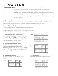
1.2.2. PS-22 Standard Components and<br />
Optional Equipment<br />
The PS-22 standard <strong>com</strong>ponents are shown in Figure 1-1 and presented<br />
in Table 1-6.<br />
2<br />
4<br />
6<br />
1<br />
3<br />
5<br />
7<br />
8<br />
9<br />
10<br />
12 13<br />
11<br />
14<br />
15<br />
Figure 1-1. PS-22 Standard Components<br />
Table 1-6. PS-22 Standard Components<br />
ITEM DESCRIPTION QTY<br />
1 Front Lens Cap 1<br />
2 <strong>ATN</strong> PS-22 Night Vision Front Sight 1<br />
3 Back Cap 1<br />
4 Light Supressor for the scopes with 30-42 mm lens diameter 1<br />
1-8
ITEM DESCRIPTION QTY<br />
5 Light Supressor for Trijicon ACOG scopes 1<br />
6 Light Supressor for the scopes with 42-63 mm lens diameter 1<br />
7 Remote Control 1<br />
8 CR123A type battery 1<br />
9 IR Illuminator IR450 Kit 1<br />
10 Picatinny Quick Release Mount 1<br />
11 Picatinny Rail 1<br />
12 QRM Wrench 1<br />
13 2.5 mm Allen Key 1<br />
14 Operator’s Manual 1<br />
15 Shipping/Storage Case 1<br />
R450-B4 IR Illuminator Kit is shown in Figure 1-2 and listed in Table 1-7.<br />
1 2 3<br />
4<br />
Figure 1-2. IR450 IR Illuminator Kit<br />
Table 1-7. IR450 Kit<br />
ITEM DESCRIPTION QTY<br />
1 IR450-B4 Illuminator 1<br />
2 CR123A type battery 1<br />
3 1,5 mm Allen Key 1<br />
4 IR450 Wrench 1<br />
1-9
Optional items are shown in Figure 1-3 and listed in Table 1-8.<br />
Table 1-8. PS-22 Optional Equipment<br />
ITEM DESCRIPTION PART CODE<br />
1 Scope Mounting System #1 ACDN<strong>PS22</strong>SM01<br />
2 Scope Mounting System #2 ACDN<strong>PS22</strong>SM02<br />
3 Scope Mounting System #3 ACDN<strong>PS22</strong>SM03<br />
4 Scope Mounting System #4 ACDN<strong>PS22</strong>SM04<br />
5 Scope Mounting System #6 ACDN<strong>PS22</strong>SM06<br />
6 7/8” Weaver Mount ACDN<strong>PS22</strong>MWVR<br />
7 Day Scope Light Suppressor ACDN<strong>PS22</strong>LSR<br />
8 Platform Ring ACWSRTRA<br />
9 Extender Focus Knob ACDN<strong>PS22</strong>EFK<br />
10 Boresight Attachment Mount (BAM) ACDN<strong>PS22</strong>BM01<br />
11 Long Rail Adapter ACWSLRADPT<br />
1 (2, 3, 4, 5) 6<br />
7<br />
8<br />
9<br />
10<br />
11<br />
Figure 1-3. PS-22 Optional Equipment<br />
1-10
SECTION II<br />
operating instructions<br />
2-1
2.1. Installation Procedures<br />
2.1.1. Quick Release Mount<br />
Quick Release Mount (QRM) is used for fast installation/removing<br />
the PS-22 on MIL-STD-1913/Picatinny rail.<br />
NOTE<br />
Optical axes of the PS-22 and the riflescope should be matched.<br />
Difference of the axes position more than 3 mm is not re-<strong>com</strong>mended.<br />
Measure the height of the riflescope axis above the rail.<br />
If the difference in the axis heights of the PS-22 and riflescope is<br />
more than 3 mm it is necessary to replace riflescope mounting<br />
rings or base by proper ones.<br />
Mount Tightness Nut<br />
2-2<br />
A<br />
Mount Lever<br />
B<br />
Figure 2-1. PS-22 Installed on MIL-STD-1913 Rail<br />
forward of Trijicon ACOG<br />
Wrench<br />
1. Slide the locking button of mount lever forward (Figure 2-1, arrow<br />
A). Turn the mount lever backwards to open the mount (Figure<br />
2-1, arrow B).<br />
2. Install the sight forward the riflescope on the arm rail as close to<br />
the riflescope as possible. The light suppressor should cover the<br />
riflescope objective lens.<br />
3. Turn the lever forwards pushing and sliding forward locking button<br />
to close the mount.
QR Mount <strong>com</strong>es factory set to securely fit most standard<br />
MIL-STD-1913/Picatinny mounts. However, there may be some<br />
slight differences in each mount from various manufacturers. You<br />
can loosen or tighten the QRM on your rail by using a 3/8” wrench<br />
and adjust the Mount Tightness Nut.<br />
NOTE<br />
If using weaver rails, please consult your gunsmith for modification<br />
to rail.<br />
2.1.2. Attachment to Day Scope Objective<br />
CAUTION<br />
The PS-22 will not attach to those riflescopes/spotting scopes which<br />
have their focusing ring on the hood of the objective lens bell.<br />
Optional Scope Mounting Systems are designed to install the<br />
PS-22 onto the riflescope/spotting scope objective lens.<br />
The Scope Mounting Systems and their inserts differ in attaching<br />
diameters and are supplied on special order with account of the<br />
parameters of the scope. To choose the proper system # and its<br />
correspondent insert refer to the Table 2-1. For example, you will<br />
need the scope mounting system #1 and 25.4 mm insert in order to<br />
mount the PS-22 onto the front lens of Leupold 1.5-5x20 PR.<br />
NOTE<br />
If scope mounting system is used, the issued weapon mount<br />
should be removed.<br />
Installation:<br />
1. Loosen two screws M2x2.5 inside the locking ring (Figure 2-2) of<br />
the scope mounting system. The locking ring must travel easily<br />
along the thread.<br />
2. Rotate the locking ring towards the body of the mounting system<br />
until full stop (the rotating direction is shown with arrow on Figure<br />
2-2). Avoid overtightening.<br />
3. Remove the Back Cap (or Light Suppressor, if it was installed)<br />
from the <strong>PS22</strong> output lens and leave it in the storage case.<br />
4. Screw the scope mounting system with insert inside into the<br />
<strong>PS22</strong> output lens thread and hand-tighten it.<br />
2-3
locking Ring<br />
INSERT<br />
Screw M2x2.5<br />
Figure 2-2. Scope Mounting System<br />
5. Loosen the fixing nut of the mounting system.<br />
6. Slide the PS-22 with attached mounting system onto the objective<br />
lens of the day scope until full stop.<br />
Dayscope Objective Lens<br />
Fixing Nut<br />
Scope Mounting System<br />
Insert<br />
Figure 2-3. <strong>PS22</strong> INSTALLED ON DAYSCOPE OBJECTIVE LENS<br />
Desirable Position of the Nut<br />
2-4<br />
Figure 2-4. Estimation of the Angle which<br />
the Scope Mounting System Should Be Turned through<br />
7. Align the seating of the <strong>PS22</strong> and its mounting system on the day<br />
scope lens. Decide on the desirable position of the nut and turn the<br />
scope mounting system until you achieve it (see arrow in Figure 2-4).<br />
8. Tighten the fixing nut hard with a screwdriver.<br />
9. Now you may turn the <strong>PS22</strong> unit to the optimal position (e.g. function<br />
switch placed strictly horizontal or canted), at your discretion.
10. Rotate the locking ring of the scope mounting system towards<br />
the <strong>PS22</strong> output lens and tighten it. It will work as a lock nut to fix<br />
the <strong>PS22</strong> position on the day scope.<br />
11. Apply a small amount of thread locker on threads and tighten the<br />
two screws M2x2.5 in the locking ring.<br />
Scope<br />
Mounting<br />
System #<br />
1<br />
2<br />
3<br />
4<br />
Table 2-1. Scope Mounting Systems<br />
Objective<br />
Lens Diameter<br />
(Insert<br />
Size), mm<br />
25,4<br />
30<br />
38<br />
42<br />
42<br />
46,7<br />
48<br />
Clear<br />
Aperture of<br />
Objective<br />
Lens, mm<br />
25.4; 30<br />
38; 42<br />
42; 46.7;<br />
48; 48.7-49;<br />
49.5; 50<br />
Riflescope Model<br />
Leupold 1.5-5x20 PR<br />
Leupold 1.5-5x20 MR/T M2<br />
Zeiss 1.1-4x24T<br />
Meopta Artemis 2000 4x32<br />
Leupold Mark 4 3-9x36<br />
Leupold Mark 4 2.5-8x36<br />
Kahles 4x36<br />
Leupold Mark 4 3-9x36<br />
Leupold Mark 4 2.5-8x36<br />
Kahles 4x36<br />
Leupold 3.5-10x40<br />
Leupold VX-II 3-9x40<br />
Zeiss 1.5-6x42<br />
Swarovski PV-N 2.5-10x42<br />
48.7-49 Meopta Artemis 3000 3-9x42<br />
49,5 Meopta Artemis 3000 4-12x40<br />
50 Shmidt & Bender 10x42<br />
56<br />
Zeiss 2.5-10x50<br />
57<br />
56; 57; 58.7<br />
Shmidt & Bender 3-12x50<br />
58,7<br />
Leupold 4.4-14x50<br />
Leupold VX-III 3.5-10x50<br />
6 62 62<br />
Zeiss 3-12x56<br />
Swarovski 2,5-10x56<br />
Kahles CSX 3-12x56<br />
2-5
<strong>PS22</strong> with QRM with Leupold<br />
Daytime Scope and IR450 on<br />
Platform Ring<br />
<strong>PS22</strong> with Leupold Daytime Scope<br />
with Scope Mounting System,<br />
Picatinny rail for IR450<br />
<strong>PS22</strong> with Leupold Daytime Scope<br />
with Scope Mounting System<br />
<strong>PS22</strong> with QRM and Trijicon ACOG<br />
<strong>PS22</strong> with Scope Mounting<br />
System and Leupold CQ/T<br />
<strong>PS22</strong> with Spotting Scope with<br />
Scope Mounting System<br />
Figure 2-5. PS-22 Mounting Examples<br />
2-6
2.1.3. extender focus knob<br />
If desired the <strong>PS22</strong> has an optional extender focus knob that can be<br />
attached to the focus ring.<br />
This knob allows for extra leverage for ease of focus adjustment.<br />
To install the extender focus knob:<br />
1. Unscrew the fixing screw. Replace it to short fixing screw(1) from<br />
extender focus knob kit. Screw the new fixing screw(1) to the lug<br />
and tighten it. Do not over tight it avoiding irregular rotation of the<br />
focus ring.<br />
2. Place knob(2) on top of focus ring knob, insuring it is properly<br />
seated.<br />
3. Tighten extender focus knob screw (3) until it is secure (do not<br />
over tighten).<br />
To remove the extender focus knob:<br />
1. Unscrew extender focus knob screw located on top of knob.<br />
2. Remove extender focus knob.<br />
3<br />
2<br />
1<br />
Figure 2-6. EXTENDER FOCUS KNOB<br />
2-7
2.2. Operating Procedures<br />
2.2.1. General<br />
This section contains instructions for placing the PS-22 in operation.<br />
The function of controls is explained.<br />
CAUTION<br />
The PS-22 is a precision electro-optical instrument and must be<br />
handled carefully at all times.<br />
CAUTION<br />
Ensure the function switch is in the off position before installing<br />
a battery.<br />
2.2.2. Controls<br />
RIGHT SIDE VIEW<br />
Focus Ring<br />
Function Switch<br />
Figure2-7. PS-22 Controls<br />
2-8
REAR VIEW<br />
Remote Control<br />
Plug Cap<br />
Plug<br />
Figure 2-8. PS-22 Controls<br />
Table 2-2. PS-22 Controls<br />
CONTROLS<br />
Function<br />
Switch<br />
Focus Ring<br />
Remote<br />
control<br />
FUNCTION<br />
STB — the sight is in standby mode.<br />
OFF — the sight is off.<br />
ON — the sight is on. Switch’s spring is loaded.<br />
Focuses the input lens. Adjusts for sharpest view of<br />
scene.<br />
Switches the sight from STB to operating mode.<br />
2-9
2.2.3. Operating Procedures<br />
These procedures should be performed under night light conditions<br />
only.<br />
CAUTION<br />
Use of the PS-22 under high light conditions may damage the<br />
image intensifier.<br />
1. Make sure the battery is installed as indicated on the sight<br />
body.<br />
2. Make visual estimation of the illumination level in the viewing<br />
area using the reference data presented in Appendix A. You can<br />
start to operate with the sight if illumination level is less than 1<br />
lux.<br />
3. Remove the Front Lens Cap and place it over the lens housing.<br />
4. Turn the power switch to the ON position. A green glow will appear<br />
in the scope eyepiece (after a slight delay).<br />
5. Observe the scene and adjust focus rotating focusing ring to<br />
achieve sharp image.<br />
CAUTION<br />
Bright sources such as light of fire, headlights, searchlights, etc.<br />
Can damage the PS-22.<br />
Take away the PS-22 from the bright sources that appear on the<br />
scene.<br />
6. If the riflescope has focusing rings (parallax adjustment knob),<br />
adjust focus for parallax free image.<br />
7. If the scope has reticle illumination, switch it on and adjust reticle<br />
brightness.<br />
8. PS-22 Shut-Down:<br />
a) Turn the function switch to OFF position. The green glow<br />
will disappear.<br />
b) Replace the protective cover on the input lens.<br />
c) If necessary remove the sight from the rail (from the scope<br />
lens) in reverse order of installing.<br />
2-10
d) Unscrew the battery cap and take out the battery. Replace<br />
the battery cap. Do not store the PS-22 with the battery still<br />
in it.<br />
e) Return the sight and all accessories to the case.<br />
2.2.4. Stowage of PS-22<br />
1. Ensure the PS-22 and all accessories are clean and dry before<br />
returning to storage case.<br />
2. Replace the objective cap and output cap on the lenses. Remove<br />
the battery.<br />
3. Make sure the sight and accessories are stored in the appropriate<br />
locations in the case and close the cover.<br />
2-11
2.3. Installation and Use of<br />
Accessories<br />
2.3.1. 7/8” Weaver Mount<br />
Optional 7/8” Weaver Mount is used for installation the PS-22 on<br />
7/8” Weaver rail instead of the issued mount.<br />
NOTE<br />
If using weaver rails, please consult your gunsmith for modification<br />
to rail.<br />
1. Loosen and remove two screws M4x8 which secure the QR<br />
mount to the sight body. Remove the QRM.<br />
CAUTION<br />
Use of screws longer than 8 mm will damage power switch.<br />
2. Put the Weaver Mount on the sight body. The mount nuts should<br />
be placed the same side as switch knob. Apply a small amount<br />
of thread locker on threads, install two screws M4x8 and tighten<br />
it.<br />
3. Loose the mount nuts. Install the sight onto the rail as close to<br />
the riflescope as possible. The light suppressor should cover the<br />
riflescope objective lens.<br />
4. Tighten the mount nuts using screwdriver.<br />
M4x8 ScrewS<br />
2-12<br />
Figure 2-9. Assembling PS-22 with 7/8” Weaver Mount<br />
2.3.2. Remote Control<br />
Remote control is designed to operate the PS-22 in short-time activation<br />
mode.
Figure 2-10. Remote Control<br />
1. Unscrew plug cap.<br />
2. Attach the remote control socket to the plug on the sight body<br />
and screw the captive nut.<br />
3. Place the control key on the fore-end of rifle stock and fix it with<br />
Velcro tape.<br />
4. To turn on the PS-22 turn the function switch in standby (STB)<br />
position. Press and hold the control key.<br />
5. After disconnecting the remote control screw the cap onto the<br />
plug.<br />
2.3.3. Picatinny Rail<br />
Optional adapter rail is used for mounting the IR 450 illuminator<br />
on the PS-22 to provide supplementary infrared illumination when<br />
operating under extremely low light conditions.<br />
M4x8 Screw<br />
Picatinny Rail<br />
Figure 2-11. Assembling PS-22 with Picatinny Rail<br />
NOTE<br />
The rail can be used if the PS-22 is installed on the dayscope<br />
lens using scope mounting system.<br />
The rail is attached to the PS-22 body with two screws M4x8<br />
instead of the issued mount (Figure 2-11).<br />
2-13
2.3.4. Platform Ring<br />
If the PS-22 is installed on MIL-STD-1913 rail, optional platform ring<br />
is used for mounting the IR 450 illuminator on dayscope with mounting<br />
diameter 25.4 or 30 mm.<br />
Attach the platform ring to your dayscope as follows:<br />
1. Unscrew the two screws from the platform ring. Use Allen<br />
wrench 2.5mm.<br />
2. If the mounting diameter of your scope is 30 mm, remove plastic<br />
inserts.<br />
3. Place the top and lower parts of the platform ring around the<br />
dayscope tube.<br />
4. Tighten hard the two screws set using screwdriver.<br />
PS-22<br />
Platform Ring<br />
IR 450<br />
Dayscope<br />
Long Rail Adapter<br />
2-14<br />
Figure 2-12. Platform Ring Mounted on Dayscope<br />
2.3.5. Long Rail Adapter<br />
Optional long rail adapter is used if the fire arm has short rail so<br />
that no place for installing the PS-22 forward of dayscope (Figure<br />
2-12).<br />
2.3.6. B.A.M. system<br />
B.A.M. system (Boresight Attachment Mount) is used to install the<br />
PS-22 Night Vision Front Sights and the dayscope on the rifles having<br />
short mounting MIL-STD-1913 rail.<br />
There are three advantages of the system:<br />
• Low position of the sight and dayscope (36 mm above the rail).<br />
• Incline of the axis of the dayscope and the sight on 20 angular<br />
minutes for long range firing.
• Resistance on the rifle with vigorous recoil.<br />
BAM System Installation:<br />
1. Slightly loosen the two fixing screws (1) on the mount base (2).<br />
2. Place the base on the mount of the fire arm (3).<br />
3. Tighten the fixing screws of mount base.<br />
4. Install the halves of plastic inserts (4) in the rings on the base.<br />
NOTE<br />
There are two sets of inserts for scopes with 25.4mm and 30mm<br />
tubes diameter.<br />
5. Cradle the scope (5) in the rings (inserts).<br />
14<br />
11<br />
12<br />
10<br />
9<br />
13<br />
8<br />
7<br />
6<br />
5<br />
4<br />
1<br />
2<br />
3<br />
Figure 2-13. Installation of B.A.M. System<br />
2-15
2-16<br />
6. Install the top halves of the inserts (6) and the rings (7) and<br />
tighten each ring’s four screws (8) to finger tight.<br />
7. Install the top of the mount (9) and tighten four screws (10) to<br />
finger tight.<br />
8. Slightly loosen the two fixing screws (11) on the top rail (12).<br />
9. Place the top rail onto the Picatinny rail on the top of the<br />
mount.<br />
10. Tighten the fixing screws of the top rail.<br />
11. Place the Night Vision Front Sight (13) onto the top rail at front<br />
of the scope. The light suppressor of the front sight should cover<br />
the riflescope objective lens.<br />
12. Place the infra-red illuminator (14) atop of the top rail.<br />
You can quickly change your system back from night vision to day.<br />
Simply unscrew two fixing screws of the top rail and take off the<br />
top rail together with the front sight and IR illuminator.<br />
NOTE<br />
The fixing screws may need to be tightened after continuous<br />
shooting.<br />
2.3.7. IR450 Illuminator<br />
Infra-red (IR) Illuminators are <strong>com</strong>mon for night vision technology.<br />
The IR light greatly enhances the performance of your device,<br />
while remaining almost totally invisible to the naked eye. Staying<br />
in the dark, switch on your night vision device. If the visibility is<br />
low, you may use <strong>ATN</strong> IR450 to improve the situation. Still, you<br />
should remember that the IR illuminator is just a source of infrared<br />
light so the greater is the chosen range of observation, the lesser<br />
its brightness be<strong>com</strong>es.<br />
IR450 Infrared Illuminator can be mounted with PS-22 onto the<br />
Picatinny Rail, Platform Ring, BAM system or on to the weapon<br />
bases.<br />
IR450 Installation:<br />
1. Loosen the fixing nut of IR450.<br />
2. Install the IR450 onto the Picatinny rail (Figure 2-5), BAM System<br />
(Figure 2-13) or Platform Ring (Figure 2-12).
3. Tighten the fixing nut of IR450 tightly.<br />
IR BRIGHTNESS ADJUSTMENT<br />
IR ELEVATION<br />
ADJUSTMENT<br />
POWER LED INDICATOR<br />
NUT<br />
BATTERY<br />
HOUSING CAP<br />
FIXING NUT<br />
IR WINDAGE<br />
ADJUSTMENT<br />
IR FOCUSING<br />
BATTERY HOUSING<br />
ALLEN KEY<br />
WRENCH<br />
Figure 2-14. IR450 Illuminator<br />
The <strong>ATN</strong> IR450 is powered with one CR123A lithium battery. To<br />
install the battery unscrew the cap of the battery housing and insert<br />
the battery following the polarity arrows marked on the housing.<br />
Put the cap in place.<br />
The IR-450 illuminator has a control panel with two buttons. To<br />
switch the IR illuminator on/off press “+” and “-” buttons simultaneously.<br />
When the IR illuminator is switched on you can see the green<br />
LED lit on the back side of IR450. By pushing the buttons “+” and<br />
“-” you may adjust the IR brightness.<br />
The IR beam is focusable to change the field of coverage. To<br />
change the beam width slightly turn the IR lens.<br />
You may need adjust the focusing of the IR beam to change the<br />
field of coverage. Do it by slightly rotating the IR lens. The windage<br />
and elevation screws help adjust the direction of the IR beam<br />
from the IR450 in order to focus on the scene observed in the<br />
viewfinder of your NVD. Use the included Allen wrench to rotate<br />
the adjusting screws until the IR beam is centered. Please remember<br />
the adjustments should be performed under night light<br />
conditions only.<br />
2-17
You can change the position of<br />
the IR control panel to meet your<br />
your needs. The wrench that is included<br />
in the set, is used to loosen<br />
the nut located on the body of the<br />
IR. Rotate the IR to the desired<br />
position. Tighten the nut with the<br />
wrench to secure the new position.<br />
Control Panel<br />
Wrench<br />
To Loosen Nut<br />
To Tighten<br />
Nut<br />
Nut<br />
Figure 2-15. CHANGING OF<br />
CONTROL PANEL POSITION<br />
2.3.8. Day Scope Light Suppressor<br />
To maximize usage of the PS-40 with a daytime scope a rubber light<br />
suppressor (DSLS) is included. The DSLS slides over the eyepiece<br />
of your daytime scope.<br />
The DSLS was designed to achieve several missions:<br />
1. Prevent back glow from the device that could give away<br />
position.<br />
2. Prevent surrounding light from interfering with image on<br />
eyepiece.<br />
The DSLS can be used with scopes that have 40...43mm eyepiece<br />
diameter and 100...120 mm eye relief.<br />
The DSLS can be adjusted for the eye relief of your scope by cutting<br />
the rubber at the desired distance.<br />
2-18<br />
Figure 2-16. Day Scope Light Suppressor
SECTION III<br />
OPERATIONAL DEFECTS<br />
3-1
3.1. ZEROING OPERATIONAL<br />
DEFECTS<br />
Operational defects refer to the reliability of the image intensifiers<br />
and are an evidence of instability. Their identification shall<br />
be a valid reason to immediately refuse to accept the <strong>ATN</strong> PS-22.<br />
These include shading, edge glow, flashing, flickering, and intermittent<br />
operation.<br />
3.1.1. Shading<br />
If shading is persistent, you will not see a fully circular image<br />
(Figure 3-1). Shading is very dark and you cannot see an image<br />
through it. Shading always begins on the edge and migrates inward<br />
eventually across the entire image area. Shading is a high<br />
contrast area with a distinct line of demarcation. Contact <strong>ATN</strong> or<br />
point of purchase for warranty/repair procedures.<br />
SHADING<br />
Figure 3-1. Shading<br />
NOTE<br />
Make sure the shading is not the result of improper exit pupil<br />
position.<br />
3-2
3.1.2. Edge Glow<br />
Edge glow is a bright area (sometimes sparkling) in the outer portion<br />
of the viewing area (Figure 3-2). To check for edge glow, block<br />
out all light by cupping a hand over the lenses. If the image tubes<br />
are displaying edge glow the bright area will still show up. Contact<br />
<strong>ATN</strong> or point of purchase for warranty/repair procedures.<br />
EDGE<br />
GLOW<br />
Figure 3-2. Edge Glow<br />
3.1.3. Flashing, Flickering, or<br />
Intermittent Operation<br />
The image may appear to flicker or flash. If there is more than one<br />
flicker, check for loose battery adapter or weak battery. Contact<br />
<strong>ATN</strong> or point of purchase for warranty/repair procedures.<br />
3.1.4. Cosmetic Blemishes<br />
These are usually the result of manufacturing imperfections that<br />
do not affect image intensifiers reliability and are not normally a<br />
reason to claim for warranty or repair work. However, some types<br />
of blemishes can get worse over time and interfere with the usability<br />
of the device. If you believe a blemish is a cause for rejection,<br />
warranty or repair please <strong>ATN</strong> or point of purchase for warranty/<br />
repair procedures.<br />
3-3
A. Bright Spots<br />
A bright spot is a small, non-uniform, bright area that may flicker or<br />
appear constant (Figure 3-3).<br />
Not all bright spots make the <strong>ATN</strong> PS-22 rejectable. Cup your hand<br />
over the lenses to block out all light. If the bright spot remains, return<br />
the <strong>ATN</strong> PS-22. Bright spots usually go away when the light is<br />
blocked out. Make sure any bright spot is not simply a bright area<br />
in the scene you are viewing. Bright spots are acceptable if they<br />
do not interfere with the ability to view the outside scene.<br />
B. Emission Points<br />
A steady or fluctuating pinpoint of bright light in the image area<br />
and does not go away when all light is blocked from the objective<br />
lenses of the Front Sight (Figure 3-3). The position of an emission<br />
point within the image area does not move. Not all emission points<br />
make the <strong>ATN</strong> PS-22 rejectable. Make sure any emission point is<br />
not simply a point light source in the scene you are viewing. Emission<br />
points are acceptable if they do not interfere with the usability<br />
of the device.<br />
EMISSION<br />
POINT<br />
BRIGHT<br />
SPOT<br />
Figure 3-3. Bright Spots and Emission Points<br />
3-4
C. Black Spots<br />
These are cosmetic blemishes in the image intensifiers or dirt or<br />
debris between the lenses. Black spots are acceptable as long as<br />
they do not interfere with viewing the image. No action is required<br />
if this condition is present unless the spots interfere with the usability<br />
of the device.<br />
D. Fixed-Pattern Noise<br />
This is usually a cosmetic blemish characterized by a faint hexagonal<br />
(honey<strong>com</strong>b) pattern throughout the viewing area that most<br />
often occurs at high light levels or when viewing very bright lights<br />
(Figure 3-4). This pattern can be seen in every image intensifier<br />
if the light level is high enough. This condition is acceptable as<br />
long as the pattern does not interfere with viewing the image and<br />
usability of the device.<br />
Figure 3-4. Fixed-Pattern Noise<br />
3-5
E. Chicken Wire<br />
An irregular pattern of dark thin lines in the field of view either<br />
throughout the image area or in parts of the image area (Figure<br />
3-5). Under the worst-case condition, these lines will form hexagonal<br />
or square-wave shaped lines. This is typically viewed in high<br />
light conditions. No action is required if this condition is present<br />
unless it interferes with the viewing the image and interferes with<br />
the users usability of the device.<br />
Figure 3-5. Chicken Wire<br />
3-6
SECTION IV<br />
maintenance instructions<br />
4-1
4.1. Preventive Maintenance<br />
Checks and Services (PMCS)<br />
4.1.1. Purpose of PMCS<br />
PMCS is performed daily when in use to be sure that the sight is<br />
ready at all times. Procedures listed in Table 4-1 are a systematic<br />
inspection of the PS-22 that will enable you to discover defects that<br />
might cause the sight to fail on a mission.<br />
4.1.2. PMCS procedures<br />
The frequency of performing PMCS is as follows:<br />
1. Daily when the sight is in use.<br />
2. When it is removed from the case for any reason.<br />
SEQ.<br />
NO.<br />
1<br />
Table 4-1. Preventive Maintenance Checks and Services<br />
ITEM TO<br />
CHECK<br />
Completeness<br />
CHECKING PROCEDURE<br />
Inventory items by means<br />
of <strong>com</strong>paring with the data<br />
specified in this manual.<br />
NOT FULLY MISSION<br />
CAPABLE IF:<br />
Items missing.<br />
2 Sight Body<br />
Inspect for missing screws<br />
or connector cap.<br />
Screws or connector<br />
cap missing.<br />
3<br />
Front Lens<br />
Cap<br />
Inspect for cuts, tears and<br />
dirt. Clean as required.<br />
Cap torn or cut.<br />
4 Back Cap<br />
Inspect for thread damage<br />
or dirt. Clean as required.<br />
Thread damage hinder<br />
installation.<br />
5<br />
Battery<br />
Compartment<br />
C h e c k for c o r r o s i o n,<br />
springs tension, cap damaged<br />
or retainer broken.<br />
Check O-ring for cuts or<br />
damage.<br />
Springs corroded or<br />
damaged. Retainer<br />
broken. Cap or O-ring<br />
damaged or missing.<br />
6<br />
Function<br />
Switch<br />
Check for operation (without<br />
battery).<br />
Switch inoperative.<br />
Knob missing.<br />
7 Lenses<br />
Inspect for cleanliness,<br />
scratches, chips or cracks.<br />
Clean as required.<br />
Chipped, cracked or<br />
if scratches hinder vision<br />
through the sight.<br />
4-2
SEQ.<br />
NO.<br />
8<br />
Table 4-1. Preventive Maintenance Checks and Services<br />
ITEM TO<br />
CHECK<br />
Objective<br />
Lens<br />
CHECKING PROCEDURE<br />
Check to ensure the objective<br />
lens is not loose.<br />
NOT FULLY MISSION<br />
CAPABLE IF:<br />
Objective lens loose.<br />
9 Focus Ring<br />
Check to ensure:<br />
— the focus ring cannot<br />
be moved along the sight<br />
body;<br />
— there is free rotation of<br />
the focus ring (more than<br />
3/4 turn).<br />
Focus ring able to<br />
move along sight body.<br />
Focus ring cannot be<br />
rotate.<br />
10<br />
11<br />
Remote<br />
Control<br />
Light<br />
Suppressor<br />
Check cable and key for<br />
damage. Check Velcro<br />
tape for wear. Ensure the<br />
remote control connects<br />
to the sight plug securely.<br />
Inspect for cuts, tears or<br />
thread damage. Check<br />
ease of installation and<br />
removal.<br />
Cable or key damaged.<br />
Velcro tape<br />
missing. Connector<br />
damage affects ability<br />
to connect remote<br />
control to the sight.<br />
Thread damage hinder<br />
installation. Suppressor<br />
torn or cut.<br />
12<br />
Mount<br />
Assembly<br />
Check for damage or corrosion.<br />
Check for proper<br />
operation.<br />
Mount body or axles<br />
damaged. Nuts missing.<br />
13 Adapter Inspect for damage.<br />
Adapter damaged,<br />
screws missing.<br />
14<br />
15<br />
Scope<br />
mounting<br />
system<br />
Installation<br />
security<br />
I n s p e c t f o r d a m a g e .<br />
Check to insure the ring<br />
is not loose. Check installation.<br />
Check the sight which<br />
installed on the arm rail<br />
or dayscope lens does<br />
not have any movement.<br />
Tighten fixing nuts if necessary.<br />
Thread or body damage<br />
hinder installation.<br />
Ring loosed. Insert<br />
or nut missing.<br />
4-3
SEQ.<br />
NO.<br />
Table 4-1. Preventive Maintenance Checks and Services<br />
ITEM TO<br />
CHECK<br />
OPERATIONAL CHECKS<br />
CHECKING PROCEDURE<br />
NOT FULLY MISSION<br />
CAPABLE IF:<br />
CAUTION<br />
Operate the PS-22 with Front Lens Cap on or under dark<br />
conditions.<br />
16<br />
Function<br />
Switch<br />
Insert the battery. Turn<br />
the switch to ON position.<br />
Look for green glow in output<br />
lens. Turn the switch to<br />
OFF position.<br />
Green glow absent.<br />
17<br />
Remote<br />
control<br />
Connect the remote control<br />
to the sight. Turn the<br />
function switch to STB position.<br />
Press and hold the<br />
key. Look for green glow in<br />
output lens. Release the<br />
key; turn the switch to OFF<br />
position.<br />
Green glow absent.<br />
18<br />
Viewed<br />
Image<br />
Check for flickering, flashing,<br />
bright spots, edge<br />
glow, shading, excessive<br />
fixed-pattern noise (honey<strong>com</strong>b).<br />
Excessive cosmetic<br />
defects or fixed pattern<br />
noise.<br />
AFTER CHECKING PROCEDURES<br />
19<br />
Replace protective covers<br />
on the lenses. Disconnect<br />
the remote control and<br />
screw up the cap. Remove<br />
the battery. Return the<br />
sight and all accessories<br />
to the storage case.<br />
4-4
4.2. Troubleshooting<br />
4.2.1. General<br />
This section contains information for locating and removal most of<br />
the PS-22 operating troubles which may occur. Each malfunction<br />
for an individual <strong>com</strong>ponent or assembly is followed by a list of tests<br />
or inspections that will help determine probable causes and corrective<br />
action to take. Perform the tests/inspections and corrective<br />
actions in the order listed.<br />
This manual cannot list all possible malfunctions that may occur,<br />
or all tests or inspections and corrective actions. If a malfunction<br />
is not listed (except when malfunction and cause are obvious), or<br />
is not corrected by listed corrective actions, contact to the service<br />
center.<br />
4.2.2. Troubleshooting Procedures<br />
Troubleshooting procedures are listed in Table 4-2.<br />
Table 4-2. Troubleshooting Procedures<br />
PROBLEM PROBABLE CAUSE CORRECTIVE ACTION<br />
Sight will not<br />
<strong>com</strong>e on.<br />
Battery is missing or<br />
improperly installed.<br />
Battery is dead.<br />
Battery contact surfaces<br />
or contact springs<br />
dirty or corroded.<br />
Defective image tube.<br />
Insert battery or install correctly.<br />
Replace battery.<br />
Clean the contact surfaces<br />
with a pencil eraser and/or<br />
alcohol and cotton swabs.<br />
Send the sight to the service<br />
center.<br />
4-5
Table 4-2. Troubleshooting Procedures<br />
PROBLEM PROBABLE CAUSE CORRECTIVE ACTION<br />
Cannot achieve<br />
the sharp image<br />
of the object.<br />
S i g h t a f fe c t s<br />
boresight after<br />
installation or<br />
during the firing.<br />
Objective and output<br />
lenses dirty.<br />
Focus ring able to<br />
move along the sight<br />
body. Locking ring<br />
loose.<br />
Damaged optical <strong>com</strong>ponents.<br />
Objective lens loose.<br />
Factory alignment broken.<br />
Loose QRM mount<br />
Clean thoroughly the lenses<br />
surfaces.<br />
Loosen and remove three<br />
screws M2x2.5. Screw the<br />
locking ring. Rotate focus<br />
ring slightly clockwise/<br />
counterclockwise. Repeat<br />
all three times. Apply a small<br />
amount of thread locker on<br />
threads, install three screws<br />
M2x2.5 and tighten.<br />
Send the sight to the service<br />
center.<br />
Screw objective lens up<br />
to the stop. Apply a small<br />
amount of thread locker on<br />
threads, install three screws<br />
M2.5x3 and tighten.<br />
Send the sight to the service<br />
center.<br />
Adjust the cam latch nut to<br />
eliminate excessive play<br />
when mounted on the rail by<br />
using the provided wrench.<br />
4-6
4.3. Maintenance Procedures<br />
4.3.1. PS-22 Maintenance<br />
The PS-22 maintenance consists of external inspection of its<br />
<strong>com</strong>ponents for serviceability, cleaning and installation of the<br />
standard and optional accessories. Maintenance instructions<br />
covered elsewhere in this manual (PMCS, troubleshooting, etc.)<br />
are not repeated in this section.<br />
CAUTION<br />
The PS-22 is a precision electro-optical instrument and must<br />
be handled carefully at all times to prevent damage.<br />
4.3.2. Cleaning Procedures<br />
A. Cleaning of the PS-22<br />
1. Gently brush off any dirt from the sight body using only a clean<br />
soft cloth.<br />
2. Moisten the cloth with fresh water and gently wipe the external<br />
surfaces (except lenses).<br />
3. Dry any wet surfaces (except lenses) with another dry and<br />
clean soft cloth.<br />
4. Using lens brush, carefully remove all loose dirt from the lenses.<br />
5. Slightly dampen a cotton swab with ethanol and lightly and<br />
slowly wipe the lenses. Clean the glass surfaces by circular<br />
movements from the centre to the edge, not touching the lens<br />
holder and changing cotton swab after each circular stroke.<br />
Repeat this step until the glass surfaces are clean.<br />
B. Cleaning of Accessories<br />
Clean accessories with a soft brush (cloth) and soap and water<br />
as required.<br />
CAUTION<br />
Dry thoroughly each item before replacing into the storage<br />
case.<br />
4-7
4.3.3. Tube Maintenance / Replacement<br />
Tube maintenance/replacement is to be performed by qualified<br />
technicians only. These procedures attempted by nonqualified<br />
personnel will void warranty.<br />
A. Tools and Equipment<br />
Next tools are necessary for this procedure:<br />
- Lock-ring spanner wrench;<br />
- Focus wrench;<br />
- Purge kit.<br />
Table 4-3 lists requirements for the equipment needed for PS-22<br />
focusing and aligning after tube replacement.<br />
Table 4-3. Equipment for PS-22 focusing and aligning.<br />
4-8<br />
Item<br />
#<br />
1 Collimator<br />
Item Parameter Requirement<br />
Focal length<br />
Exit pupil diameter<br />
Focusing distance<br />
Test pattern<br />
250 to 800 mm<br />
80 mm<br />
Infinity<br />
Crosshair<br />
Pattern illumination Daytime mode<br />
Nighttime mode<br />
2 Mounting rail Type MIL-STD-1913<br />
Magnification 6 to 12<br />
3 Telescope<br />
Entrance pupil diameter 22 to 56 mm<br />
Focusing distance Infinity<br />
Reticle<br />
Crosshair<br />
B. Tube Removal<br />
- Loosen three fixing screws (Figure 4-1, 2).<br />
- Unscrew and remove the objective lens (Figure 4-1, 1).<br />
- Unscrew and remove the lock ring (Figure 4-1, 7).<br />
- Draw out the spring washer («Glass/GLASS» tube only, Figure<br />
4-1, 8).<br />
- Take out defective image intensifier tube.
Below the actions for «Glass/GLASS» tube only are listed:<br />
- Accurately separate the <strong>com</strong>pensator glass (Figure 4-1, 9)<br />
from the tube for second using.<br />
- Unsolder tube wires from the board on the tube end (Figure<br />
4-2). Accurately separate the board (Figure 4-2, 1) from the<br />
tube for second using.<br />
C. Tube Installation<br />
«Glass/glass» tube preparation:<br />
- Shorten tube wires up to 30 mm, strip insulation and tinning<br />
the wires.<br />
- Bend tinning ends of the wires and solder it to the board according<br />
polarity marking on the tube body and the board.<br />
- Align the board groove with the tube groove and glue the board<br />
(Figure 4-2, 1) onto the rear end surface of the tube (Figure<br />
4-2, 2).<br />
- Lay the wires into the tube groove and fix them with glue.<br />
- Thoroughly clean the <strong>com</strong>pensator glass.<br />
- Apply small amount of glue on the glass and install it into the<br />
tube.<br />
Tube installation:<br />
- Thoroughly clean input and output windows of the tube.<br />
- Insert the tube into the tube <strong>com</strong>partment. Be sure to engage<br />
the groove on the tube body with a pin in the tube <strong>com</strong>partment.<br />
- Install the spring washer («Glass/GLASS» tube only, Figure<br />
4-1, 8).<br />
- Apply small amount of thread locker and screw the locking ring<br />
(Figure 4-1, 7). Do not over tighten it.<br />
- Screw the objective lens (Figure 4-1, 1); put the lens cap (Figure<br />
4-1, 6) on.<br />
CAUTION<br />
All testing and alignment procedures must be done in dark<br />
room (illumination level less than 0.3 Lx)<br />
4-9
NOTE<br />
If special attenuator filter is used, testing and alignment procedure<br />
could be done in the normal illuminated room and the<br />
collimator pattern illuminator could have only daytime mode.<br />
Attenuator filter have to be neutral glass filter with density 4<br />
to 5. The filter effective diameter should be 63 mm and surface<br />
parallelism within 1 MOA. It is installed in the housing to mount<br />
on the sight.<br />
D. Equipment Preparing<br />
- Provide coaxial position of the collimator, the sight and the<br />
telescope.<br />
- Align the mounting rail with the collimator and fix it firmly. The<br />
angle between rail axis and collimator axis within 5 MOA.<br />
- Adjusting angular position of the telescope match its crosshair<br />
with collimator crosshair.<br />
E. Objective Lens Focusing<br />
- Switch the collimator pattern illuminator on in nighttime mode.<br />
- Rotate the focus ring (Figure 4-3, 4) of the sight to achieve<br />
sharp image of collimator pattern.<br />
- Check driving ring lug position (Figure 4-3, 8). The lug on the<br />
driving ring should be turn counterclockwise and a gap under<br />
the lug should be equal the thickness of your thumb.<br />
- If the lug position is different, unscrew the screw (Figure 4-3,<br />
11) and remove the extender focus knob (Figure 4-3, 10).<br />
Loose the fixing screw (Figure 4-3, 9) in the lug and rotate the<br />
driving ring to the right position. Tighten the fixing screw. Do<br />
not over tight it avoiding irregular rotation of the focus ring. Install<br />
the lever to the place.<br />
- Rotate focus ring clockwise. The travel must be ¾ of turn for<br />
focusing on close objects.<br />
- If sharp image has not been achieved or focus ring can not be<br />
rotated ¾ of turn, align the objective lens position as follows:<br />
- Loosen three fixing screws (Figure 4-3, 5).<br />
- Unscrew the lock ring (Figure 4-3, 6) and move it towards the<br />
battery <strong>com</strong>partment.<br />
4-10
1<br />
2<br />
3<br />
4<br />
5<br />
6<br />
2<br />
7<br />
11<br />
8<br />
3<br />
9 10<br />
3<br />
Figure 4-1. tube replacement<br />
12<br />
13<br />
14<br />
2<br />
Figure 4-2. installation of the board to the tube<br />
1<br />
1 2<br />
3<br />
4<br />
5<br />
6<br />
5<br />
3<br />
5 3 7<br />
8 9<br />
10 11<br />
Figure 4-3. Objective lens focusing<br />
4-11
- Rotate the focus ring (Figure 4-3, 4) counterclockwise to open<br />
the objective thrust ring (Figure 4-3, 2). Not allow to fall the<br />
threaded segments out.<br />
- Loosen three fixing screws (Fiigure 4-3, 3).<br />
- Move the focus ring (Figure 4-3, 4) towards the objective lens.<br />
- Rotate the objective lens (Figure 4-3, 1) and the thrust ring<br />
(Figure 4-3, 2) together to achieve sharp image of collimator<br />
pattern.<br />
- Rotate the thrust ring (Figure 4-3, 2) ¼ of turn counterclockwise<br />
and tighten fixing screws (Figure 4-3, 3) lightly.<br />
- Unscrew fixing screws (Figure 4-3, 3) one by one, drill dimples<br />
through the holes in the ring, apply small amount of thread<br />
locker and secure the thrust ring with fixing screws.<br />
- Rotate the focus ring (Figure 4-3, 4) clockwise up to the stop.<br />
- Screw the lock ring (Figure 4-3, 6).<br />
- Rotate the focus ring clockwise/counterclockwise three<br />
times.<br />
- Tight the lock ring (Figure 4-3, 6) lightly.<br />
- Unscrew fixing screws (Figure 4-3, 6) one by one, drill dimples<br />
through the holes in the ring, apply small amount of thread<br />
locker and secure the lock ring with fixing screws.<br />
- Screw the objective lens (Figure 4-3, 1) up to the stop.<br />
- Unscrew fixing screws (Figure 4-1, 2) one by one, drill dimples<br />
through the holes in the housing, apply small amount of thread<br />
locker and secure the objective lens with fixing screws.<br />
F. Preparing the Sight For Alignment<br />
- Carefully separate the rubber cover (Figure 4-1, 4) from the<br />
sight body and remove it.<br />
- Unscrew and remove the lock ring (Figure 4-1, 14).<br />
- Loosen three adjusting screws (Figure 4-1, 3).<br />
- Cut out old sealant and remove output lens assembly (Figure<br />
4-1, 11).<br />
- Thoroughly clean the output lens assembly and all internal<br />
surfaces of the unit including adjustment screws from sealant<br />
debris and any dirt.<br />
4-12
- Replace the output lens assembly (Figure 4-1, 11) and tighten<br />
three adjustment screws (Figure 4-1, 3) lightly.<br />
- Screw and tighten lightly the lock ring (Figure 4-1, 14).<br />
G. Output Lens Focusing<br />
- Switch the collimator pattern illuminator on in nighttime mode.<br />
- Put the sight onto the mounting rail, switch it on and rotate<br />
focus ring (Figure 4-3, 4) to achieve sharp image.<br />
- Unscrew the output lens on 1.5- 2 mm and apply transparent<br />
glue or black primer.<br />
- Rotate output lens (Figure 4-1, 11) with focus wrench to achieve<br />
parallax free image.<br />
H. Boresight Alignment<br />
- Switch the collimator pattern illuminator on in daytime mode<br />
- Without the sight, looking through the telescope check matching<br />
it’s crosshair with collimator crosshair.<br />
- Switch the collimator pattern illuminator on in nighttime mode.<br />
- Put the sight onto the mounting rail, switch it on and rotate<br />
focus ring to achieve sharp image.<br />
- Looking through the telescope, turn adjustment screws (Figure<br />
4-1, 3) to match image of collimator crosshair with crosshair of<br />
the telescope.<br />
- Switch the sight off and remove it from the rail.<br />
- Unscrew and remove the lock ring (Figure 4-1, 14).<br />
- Fill the gap between the output lens assembly (Figure 4-1, 11)<br />
and sight body with sealant.<br />
- Screw the lock ring (Figure 4-1, 14) and tight it firmly.<br />
- Check boresighting and correct if necessary.<br />
I. Nitrogen Purge<br />
- Remove the purge screw (Figure 4-3, 7).<br />
- Check airtightness of the sight and fill it with dry nitrogen.<br />
- Apply small amount of sealant and install the purge screw.<br />
- Put the rubber cover (Figure 4-1, 4) onto the sight body and<br />
secure it with glue.<br />
4-13
APPENDIX A<br />
(Reference)<br />
ESTIMATION OF AMBIENT<br />
ILLUMINATION LEVEL<br />
Table A-1. Standard Natural Light Conditions and<br />
Illumination Values<br />
STANDARD NATURAL LIGHT<br />
CONDITIONS<br />
ILLUMINATION VALUE,<br />
LUX<br />
Quarter moon 0.05<br />
Full moon 0.30<br />
Late twilight sky 1.00<br />
Twilight sky 10.00<br />
Overcast sky in the daytime 500.00<br />
A-1
APPENDIX B<br />
spare PARTS LIST<br />
The Spare Parts List is an illustrated catalog of main parts and<br />
assemblies <strong>com</strong>pleting the Night Vision Sight PS-22, here in after<br />
referred to as PS-22.<br />
Therefore, in case of failure of any part or assembly <strong>User</strong> could<br />
replace it by ordering the corresponding part/assembly from the<br />
Spare Parts List. The amount and assortment of the spare parts<br />
needed should be arranged with each contract individually.<br />
Table B-1. <strong>ATN</strong> PS-22 spare parts list<br />
PART NO. DESCRIPTION FIG. ITEM<br />
AT 146541.700 Night Vision Sight B1<br />
AT 146541.701 Objective Assembly B1 1<br />
AT 146541.702 Objective Directive Screws B1 2<br />
AT 146541.703<br />
Body (with Objective Focusing and<br />
Locking Rings)<br />
B1 3<br />
AT 146541.704 Objective Directive Screws B1 4<br />
AT 146541.705 Rubber Cover B1 5<br />
AT 146541.706 Back Cap B1 6<br />
AT 146541.707 Front Lens Cap B1 7<br />
AT 146541.708 Lock Ring B1 8<br />
AT 146541.709 Spring Washer B1 9<br />
AT 146541.710 Compensator Glass B1 10<br />
AT 146541.711 Image Intensifier Tube B1 11<br />
AT 146541.717 Lever B1 12<br />
AT 146541.718 Screw B1 13<br />
AT 146541.712 Rubber Cord B1 14<br />
AT 146541.713 Battery Cap B1 15<br />
B-1
Table B-1. <strong>ATN</strong> PS-22 spare parts list<br />
PART NO. DESCRIPTION FIG. ITEM<br />
AT 146541.714 Plug Cap B1 16<br />
AT 146541.715 Output Lens Assebly B1 17<br />
AT 146541.716 Lock Ring B1 18<br />
AT 146542.700 Accessories 1 (From the Kit) B2<br />
AT 146542.710<br />
AT 146542.711<br />
AT 146542.712<br />
Light Supressor for the scopes with<br />
42-63 mm lens diameter<br />
Light Supressor for Trijicon ACOG<br />
scopes<br />
Light Supressor for the scopes with<br />
30-42 mm lens diameter<br />
B2 1<br />
B2 2<br />
B2 3<br />
AT 541002.702 QRM mount (with two M4x7 screws) B2 4<br />
AT 541002.713 Remote Control B2 5<br />
AT 146533.704 Picatinny Rail B2 6<br />
AT 146533.565 IR Illuminator IR450 Kit B2 7<br />
AT 146533.566 QRM Wrench B2 8<br />
AT 146533.567 2.5 mm Allen Key B2 9<br />
AT 541002.703 Operator's Manual B2 10<br />
AT 3187393 Shipping/Storage Case B2 11<br />
AT 146533.700 Accessories 2 (Optional) B3<br />
AT 146533.751 Scope Mounting System #1 B3 1<br />
AT 146533.752 Scope Mounting System #2 B3 1<br />
AT 146533.753 Scope Mounting System #3 B3 1<br />
AT 146533.754 Scope Mounting System #4 B3 1<br />
AT 146533.755 Scope Mounting System #6 B3 1<br />
AT 146534.751<br />
Scope Mounting System Insert with<br />
25.4 mm diameter<br />
B3 2<br />
B-2
Table B-1. <strong>ATN</strong> PS-22 spare parts list<br />
PART NO. DESCRIPTION FIG. ITEM<br />
AT 146534.752<br />
AT 146534.753<br />
AT 146534.754<br />
AT 146534.755<br />
AT 146534.756<br />
AT 146534.757<br />
AT 146534.758<br />
AT 146534.759<br />
AT 146534.760<br />
AT 146534.761<br />
AT 146534.762<br />
AT 146534.763<br />
Scope Mounting System Insert with<br />
30 mm diameter<br />
Scope Mounting System Insert with<br />
38 mm diameter<br />
Scope Mounting System Insert with<br />
42 mm diameter<br />
Scope Mounting System Insert with<br />
46.7 mm diameter<br />
Scope Mounting System Insert with<br />
48 mm diameter<br />
Scope Mounting System Insert with<br />
48.7-49 mm diameter<br />
Scope Mounting System Insert with<br />
49.5 mm diameter<br />
Scope Mounting System Insert with<br />
50 mm diameter<br />
Scope Mounting System Insert with<br />
56 mm diameter<br />
Scope Mounting System Insert with<br />
57 mm diameter<br />
Scope Mounting System Insert with<br />
58.7 mm diameter<br />
Scope Mounting System Insert with<br />
62 mm diameter<br />
B3 2<br />
B3 2<br />
B3 2<br />
B3 2<br />
B3 2<br />
B3 2<br />
B3 2<br />
B3 2<br />
B3 2<br />
B3 2<br />
B3 2<br />
B3 2<br />
AT 146533.741 Long Rail Adapter B3 3<br />
AT 146539.701 7/8” Weaver Mount B3 4<br />
AT 146533.702 Platform Ring B3 5<br />
AT 146533.750 Extender Focus Knob B3 6<br />
B-3
Table B-1. <strong>ATN</strong> PS-22 spare parts list<br />
PART NO. DESCRIPTION FIG. ITEM<br />
AT 146533.706 Day Scope Light Suppressor B3 7<br />
AT 146533.751 Boresight Attachment Mount (BAM) B3 8<br />
1<br />
2<br />
3<br />
4<br />
5<br />
6<br />
7<br />
2<br />
8<br />
9<br />
10<br />
11<br />
3<br />
14 15<br />
3<br />
16<br />
17<br />
18<br />
Figure B-1. NIGHT VISION SIGHT<br />
1<br />
3<br />
2 4 5<br />
7<br />
8<br />
12 13<br />
7<br />
9<br />
10<br />
11<br />
6<br />
Figure B-2. Accessories 1 (From the Kit)<br />
1<br />
3<br />
2<br />
5<br />
4<br />
8<br />
6<br />
Figure B-3. Accessories 2 (Optional)<br />
B-4
APPENDIX C<br />
How to select Scope Mounting System<br />
required for your daytime scope<br />
By selecting the appropriate Scope Mounting System (with Inserts)<br />
you can mount the PS-22 onto a daytime scope with an<br />
objective tube diameter from 25 to 62 mm. At the Table 2-1 Scope<br />
Mounting System sizes (#1-6) and Insert sizes for different scope<br />
examples are provided.<br />
If your specific daytime scope is not listed in Table 2-1, before<br />
mounting procedure you have to select the proper Scope Mounting<br />
System (and Insert) required.<br />
To do this, perform the following actions:<br />
1. Determine your daytime scope objective tube diameter (external<br />
- not diameter of the glass lens) with a millimeter ruler<br />
(with a trammel for more accurate results) as shown in figure<br />
C-1.<br />
2. Select from the Table 2-1 the Insert size closest (larger) to<br />
the value measured (Insert size is also specified at an Insert<br />
body). Do the selection in Insert group that corresponds to the<br />
same Scope Mounting System (for example, Scope Mounting<br />
System #2).<br />
3. The Scope Mounting System you need is the one that corresponds<br />
to Insert size selected<br />
at the Table 2-1.<br />
For example, if your scope objective<br />
tube diameter is equal to<br />
46 mm then you should select<br />
Insert with size of 46,7 mm and<br />
corresponding Scope Mounting<br />
Systems #3 from the Table 2-1.<br />
Figure C-1.<br />
Objective tube diameter<br />
measuring<br />
C-1
For Technical Information<br />
<strong>ATN</strong> Corp.<br />
1341 San Mateo Avenue<br />
South San Francisco, CA 94080<br />
(800) 910-2862<br />
(650) 989-5100 tel.<br />
(650) 875-0129 fax<br />
www.atncorp.<strong>com</strong><br />
info@atncorp.<strong>com</strong><br />
INFO-1
INFO-1
For customer service and<br />
technical support, please contact<br />
American Technologies Network Corp.<br />
North American Office:<br />
1341 San Mateo Avenue<br />
South San Francisco, CA 94080<br />
phone: 800-910-2862, 650-989-5100<br />
fax: 650-875-0129<br />
www.atncorp.<strong>com</strong><br />
©2010 <strong>ATN</strong> Corporation