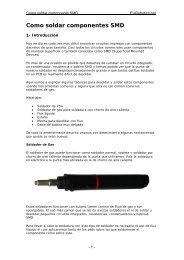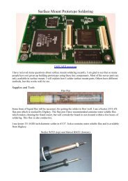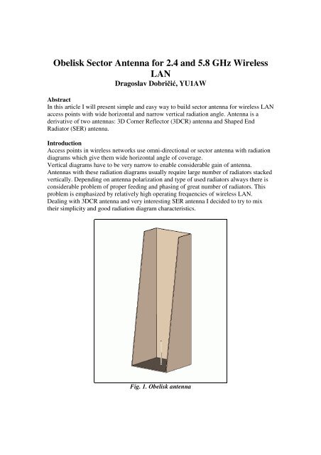
Obelisk Sector Antenna for 2.4 and 5.8 GHz Wireless LAN - ATVA
Obelisk Sector Antenna for 2.4 and 5.8 GHz Wireless LAN - ATVA
Obelisk Sector Antenna for 2.4 and 5.8 GHz Wireless LAN - ATVA

You also want an ePaper? Increase the reach of your titles
YUMPU automatically turns print PDFs into web optimized ePapers that Google loves.
<strong>Obelisk</strong> <strong>Sector</strong> <strong>Antenna</strong> <strong>for</strong> <strong>2.4</strong> <strong>and</strong> <strong>5.8</strong> <strong>GHz</strong> <strong>Wireless</strong><br />
<strong>LAN</strong><br />
Dragoslav Dobričić, YU1AW<br />
Abstract<br />
In this article I will present simple <strong>and</strong> easy way to build sector antenna <strong>for</strong> wireless <strong>LAN</strong><br />
access points with wide horizontal <strong>and</strong> narrow vertical radiation angle. <strong>Antenna</strong> is a<br />
derivative of two antennas: 3D Corner Reflector (3DCR) antenna <strong>and</strong> Shaped End<br />
Radiator (SER) antenna.<br />
Introduction<br />
Access points in wireless networks use omni-directional or sector antenna with radiation<br />
diagrams which give them wide horizontal angle of coverage.<br />
Vertical diagrams have to be very narrow to enable considerable gain of antenna.<br />
<strong>Antenna</strong>s with these radiation diagrams usually require large number of radiators stacked<br />
vertically. Depending on antenna polarization <strong>and</strong> type of used radiators always there is<br />
considerable problem of proper feeding <strong>and</strong> phasing of great number of radiators. This<br />
problem is emphasized by relatively high operating frequencies of wireless <strong>LAN</strong>.<br />
Dealing with 3DCR antenna <strong>and</strong> very interesting SER antenna I decided to try to mix<br />
their simplicity <strong>and</strong> good radiation diagram characteristics.<br />
Fig. 1. <strong>Obelisk</strong> antenna
<strong>Obelisk</strong> antenna <strong>for</strong> <strong>2.4</strong> <strong>GHz</strong><br />
<strong>Antenna</strong> has one active element <strong>and</strong> suitable shaped reflector around it.<br />
Reflector is similar as two 3DCR antennas stacked <strong>and</strong> overlapped side by side <strong>and</strong><br />
connected to per<strong>for</strong>m as one solid cast reflector. This gives reflector with four planes<br />
instead of three planes as in 3DCR antennas.<br />
Radiator positions <strong>for</strong> both 3DCR antennas are also overlapped. As result we got three<br />
side reflector planes <strong>and</strong> one ground plane with monopole at its center, as can be seen on<br />
Fig.1.<br />
By increasing reflector height we got narrower vertical diagram <strong>and</strong> higher gain of<br />
antenna. Specific shape of two side reflector planes widen horizontal radiation diagram<br />
<strong>and</strong> also improved side lobe suppression in vertical plane.<br />
Fig. 2. <strong>Obelisk</strong> antenna <strong>for</strong> <strong>2.4</strong> <strong>GHz</strong> horizontal radiation diagram.<br />
With such reflector construction antenna has widen its horizontal radiation diagram to 40<br />
deg. which is almost double compared to 3DCR antenna. Due to wider horizontal<br />
diagram, gain decreases <strong>for</strong> about 2 dB comparing to 3DCR antenna.<br />
Vertical diagram is also changed but not so much except it becomes more elevated then<br />
in 3DCR antenna. In 3DCR antenna vertical diagram is elevated about 45 deg, but in<br />
<strong>Obelisk</strong> antenna this elevation angle of main lobe increased to 54 deg.
Fig. 3. <strong>Obelisk</strong> antenna vertical radiation diagram.<br />
Fig. 4. <strong>Obelisk</strong> antenna 3D radiation diagram.
Fig. 5. <strong>Obelisk</strong> antenna input SWR <strong>and</strong> S11 parameter in dB <strong>for</strong> <strong>2.4</strong> <strong>GHz</strong>.<br />
<strong>Antenna</strong> constructed on this way become similar with SER antenna except that there is no<br />
piece of waveguide as in SER antenna. As a consequence radiation characteristics <strong>and</strong><br />
input impedance of antenna changed in relation to both 3DCR <strong>and</strong> SER antennas.<br />
To get optimum radiation diagram, gain <strong>and</strong> working b<strong>and</strong>width it was necessary to<br />
per<strong>for</strong>m reflector shape optimization. Given final dimensions are the best compromise<br />
between electrical properties <strong>and</strong> mechanical size of <strong>Obelisk</strong> antenna.<br />
<strong>Antenna</strong> mounted to radiate vertical polarization wave has horizontal radiation diagram<br />
of about 40 deg. <strong>for</strong> -3 db <strong>and</strong> vertical diagram of about 19 deg <strong>for</strong> -3dB, elevated 54 deg<br />
in relation to radiator ground plane.<br />
Radiator is simple monopole made of 0.74 wavelength long copper wire.<br />
Input impedance is 50 ohms <strong>and</strong> return loss <strong>and</strong> SWR diagrams are given <strong>for</strong> both<br />
<strong>Wireless</strong> <strong>LAN</strong> b<strong>and</strong>s.<br />
<strong>Antenna</strong> gain is about 16 dBi with clear diagram <strong>and</strong> relatively high side lobes<br />
suppression.
Fig. 6. Dimensions of <strong>Obelisk</strong> antenna <strong>for</strong> <strong>2.4</strong> <strong>GHz</strong> fequency.<br />
Mechanical construction<br />
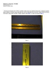
<strong>Obelisk</strong> antenna reflector is built from copper or brass tin. Whole reflector can be cut out<br />
from one piece o tin according to cut scheme given at Fig.2 <strong>and</strong> folded perpendicular<br />
along dashed lines. Dimensions of reflector are given on Fig3<br />
After cutting <strong>and</strong> bending it is necessary to connect horizontal ground plane with side<br />
planes by soldering connection at the outer side of the antenna.. That means that entire<br />
reflector surface in all four planes must behave as continuous surface with good electric<br />
contact along the whole length at connections between each reflector surfaces. It is very<br />
important to have good electric contact between plates because of currents which flow
over reflector surface parallel with radiator axis. If contact between plates is weak,<br />
reflector surface currents are broken <strong>and</strong> antenna works poorly. The reflector surface of<br />
the antenna must be built almost as it is cast solid!<br />
Some builders made it from aluminum but with special attention to good connection<br />
provided by aluminum L profile <strong>and</strong> large number of pop-rivets as it is shown on pictures<br />
of built <strong>Obelisk</strong> antenna.<br />
At the center of ground plane is mounted female N or SMA connector. At the center pin<br />
of female connector is soldered monopole made of copper wire. Dimensions of monopole<br />
are given on Fig. 9.<br />
Fig. 7. Shape <strong>and</strong> dimensions of cut <strong>for</strong> <strong>Obelisk</strong> antenna <strong>for</strong> <strong>2.4</strong> <strong>GHz</strong>.
Fig. 8. Dimensions of <strong>Obelisk</strong> antenna monopole position <strong>for</strong> <strong>2.4</strong> <strong>GHz</strong>.<br />
Fig. 9. Dimensions of <strong>Obelisk</strong> antenna monopole <strong>for</strong> <strong>2.4</strong> <strong>GHz</strong>.
Weather protection<br />
Reflector surface <strong>and</strong> driver monopole are protected from corrosion by thin layer of<br />
varnish which is evenly deposited using spray.<br />
It is important to do that be<strong>for</strong>e corrosion start to change bright color of metal parts.<br />
Soldering point of monopole <strong>and</strong> connector cross section can be protected from weather<br />
by thin film of melted polyethylene deposit.<br />
Fig. 10. Mounting of <strong>Obelisk</strong> antenna with dimensions <strong>for</strong> <strong>2.4</strong> <strong>GHz</strong>.<br />
<strong>Antenna</strong> mounting<br />
Similar as 3DCR the unusual thing while using this antenna is its aiming.<br />
<strong>Obelisk</strong> antenna has elevated vertical diagram <strong>and</strong> mounting of antenna have to be done<br />
on such way that this elevation would be compensated in order to have radiation toward<br />
horizon. The easiest way to do that is to mount antenna as shown on Fig.5.<br />
Such antenna mounting improve protection from collecting rain <strong>and</strong> snow inside antenna<br />
structure.
<strong>Obelisk</strong> antenna <strong>for</strong> <strong>5.8</strong> <strong>GHz</strong><br />
Simplicity <strong>and</strong> good characteristics of <strong>Obelisk</strong> antenna looked promising <strong>for</strong> <strong>5.8</strong> <strong>GHz</strong><br />
b<strong>and</strong>. Only problem I saw was very wide working b<strong>and</strong> <strong>and</strong> I was not sure if <strong>Obelisk</strong><br />
antenna could cover whole b<strong>and</strong> with acceptable SWR.<br />
After some minor optimization I got acceptable SWR over whole <strong>5.8</strong> <strong>GHz</strong> b<strong>and</strong> as can be<br />
seen on Fig. 11.<br />
<strong>Antenna</strong> construction is very tolerant to dimension errors <strong>and</strong> that is quality which is<br />
important <strong>for</strong> successful antenna building at high frequencies.<br />
Fig. 11. <strong>Obelisk</strong> antenna input SWR <strong>and</strong> S11 parameter in dB <strong>for</strong> <strong>5.8</strong> <strong>GHz</strong>.<br />
Fig. 12. Horizontal radiation diagram of <strong>Obelisk</strong> antenna <strong>for</strong> <strong>5.8</strong> <strong>GHz</strong>.
Fig. 13. Vertical radiation diagram of <strong>Obelisk</strong> antenna <strong>for</strong> <strong>5.8</strong> <strong>GHz</strong>.<br />
Fig. 14. 3D radiation diagram of <strong>Obelisk</strong> antenna <strong>for</strong> <strong>5.8</strong> <strong>GHz</strong>.
Fig. 15. Dimensions of <strong>Obelisk</strong> antenna <strong>for</strong> <strong>5.8</strong> <strong>GHz</strong> frequency.
Fig. 16. Dimensions of <strong>Obelisk</strong> antenna monopole position <strong>for</strong> <strong>5.8</strong> <strong>GHz</strong>.<br />
Fig. 17. Dimensions of <strong>Obelisk</strong> antenna monopole <strong>for</strong> <strong>5.8</strong> <strong>GHz</strong>.
Fig. 18. Mounting of <strong>Obelisk</strong> antenna with dimensions <strong>for</strong> <strong>5.8</strong> <strong>GHz</strong>.<br />
Conclusion<br />
<strong>Obelisk</strong> antenna, according to results, justified its ability to serve as good access point<br />
antenna in <strong>Wireless</strong> <strong>LAN</strong> on frequencies of <strong>2.4</strong> <strong>and</strong> <strong>5.8</strong> <strong>GHz</strong>. Its simplicity <strong>and</strong> tolerant<br />
design gives promising building.<br />
Fig. 19. <strong>Obelisk</strong> antenna <strong>for</strong> <strong>5.8</strong> <strong>GHz</strong> made of copper.
Fig. 20. <strong>Obelisk</strong> antenna <strong>for</strong> <strong>2.4</strong> <strong>GHz</strong> made of brass with mounting acessories.<br />
Fig. 21. <strong>Obelisk</strong> antenna <strong>for</strong> <strong>2.4</strong> <strong>GHz</strong> made of aluminium with mounting acessories.
Fig. 22. <strong>Obelisk</strong> antenna <strong>for</strong> <strong>5.8</strong> <strong>GHz</strong> made of aluminium.
Reference<br />
1. Shortened 3D corner reflector antenna (antenneX, issue number 125)<br />
2. 3D corner reflector antenna feed <strong>for</strong> <strong>5.8</strong> <strong>GHz</strong> (antenneX, issue number 126)