Backflow protection devices - WATTS industries
Backflow protection devices - WATTS industries
Backflow protection devices - WATTS industries

You also want an ePaper? Increase the reach of your titles
YUMPU automatically turns print PDFs into web optimized ePapers that Google loves.
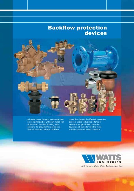
<strong>Backflow</strong> <strong>protection</strong><br />
<strong>devices</strong><br />
All water users demand assurance that<br />
no contaminated or unknown water can<br />
siphon back into the drinking water<br />
network. To provide this assurance,<br />
Watts Industries delivers backflow<br />
<strong>protection</strong> <strong>devices</strong> in different <strong>protection</strong><br />
classes. Watts Industries offers an<br />
extensive range of flow <strong>protection</strong><br />
<strong>devices</strong> and can offer you the most<br />
suitable solution for each situation.
BACKFLOW PROTECTION DEVICES<br />
OUR EUROPEAN PRESENCE<br />
2<br />
H e a d q u a r t e r s<br />
M a n u f a c t u r i n g a n d s a l e s<br />
M a n u f a c t u r i n g<br />
S a l e s
BACKFLOW PROTECTION DEVICES<br />
CONTENTS<br />
INTRODUCTION PAGE 4<br />
3<br />
PROTECTION MATRIX PAGE 6<br />
BA 909 DN 20 THROUGH DN 50 PAGE 7<br />
BA 909 DN 65 THROUGH DN 250 PAGE 9<br />
BA 009 PAGE 12<br />
BA BS MICRO PAGE 16<br />
CA 9C PAGE 17<br />
DA 288A PAGE 19<br />
EA & EB CHECK VALVES PAGE 20<br />
EA FC PAGE 23<br />
HA S8C/NF8 PAGE 25<br />
HD N9/NLF9 PAGE 26<br />
TERMS AND DEFINITIONS PAGE 27
BACKFLOW PROTECTION DEVICES<br />
4<br />
Introduction<br />
The possibility of pollution of drinking water pipelines is a risk not to<br />
be overlooked. In fact, public opinion is very much aware of the<br />
problem, especially after the increased information and concern in the<br />
ecological field, which has led legislators to gradually adapt the<br />
European standards.<br />
In this connection considerable resources have been invested in<br />
technological research and manufacture of a range of equipment and<br />
accessories designed to prevent pollution of the water in the<br />
distribution systems.<br />
The European Ministry of Health have issued regulations and acts<br />
providing local administrations and private individuals with preventive<br />
and control measures against pollution of drinking water. There are<br />
two conditions which can give rise to a similar contamination:<br />
- contact between non-drinkable water and drinking water<br />
- risk of return of pollutants to the drinking water supply<br />
The EN 1717 is a <strong>protection</strong> method based on a classification of water<br />
into 5 liquids categories and a classification of pressure levels for the<br />
connections between the drinking water network and one of these<br />
liquids categories. Using these parameters, an installation matrix can<br />
be drawn up. Projecting the installation matrix onto the <strong>protection</strong><br />
matrix, which specifies the maximum level of <strong>protection</strong> for every<br />
<strong>protection</strong> device, provides the most adequate security.<br />
1. The installation matrix<br />
The installation matrix offers a method for analysing an existing<br />
drinking water installation, or one that must be designed, specifying<br />
information regarding the nature of the connection and the possible<br />
contact. A coloured dot indicates the existence of the parameter.<br />
A white dot indicates that the parameter does not exist.<br />
2. The <strong>protection</strong> matrix<br />
The <strong>protection</strong> matrix indicates the <strong>protection</strong> options for specific<br />
<strong>protection</strong> units, consisting of a <strong>protection</strong> device (e.g. the Watts CA<br />
9D or the Watts BA 009) and the requisite peripheral components,<br />
such as ball valves and filters. Obviously, each device has its own<br />
matrix (see page 6). A coloured dot indicates that security is<br />
guaranteed for the parameter for the relevant cell. A white dot means<br />
that such security is not guaranteed.<br />
3. Selecting equipment<br />
If an installation must be protected against backflow, an installation<br />
matrix should be created for this installation. This enables one to<br />
select the right Watts Industries equipment with the right security<br />
features for this particular installation. In so doing, you must ensure<br />
that the coloured dot in the installation matrix is covered by a coloured<br />
dot in the <strong>protection</strong> matrix.<br />
Installation parameters<br />
P=atm<br />
P>atm<br />
H<br />
P=atm: Atmospheric pressure<br />
No existing or possible reverse pressure from water column (H)<br />
or overpressure (P) directly downstream of the selected<br />
installation point for the <strong>protection</strong> device.<br />
Back siphonage: when the pressure in the supply main is lower<br />
than the branch circuit; for example, owing to a break in the<br />
piping or interruption in the drinking water supply.<br />
Liquids categories<br />
In normal use fluids which are or can<br />
be in contact with potable water are<br />
classified in five categories as<br />
defined below.<br />
In cases where insignificant<br />
concentrations or substantial<br />
amounts of substances are present it<br />
may be appropriate to redefine the<br />
safety measurement.<br />
Category 1:<br />
Water to be used for human<br />
consumption coming directly from a<br />
potable water distribution system.<br />
Category 2:<br />
Fluid presenting no human health<br />
hazard.<br />
Fluid recognised as being fit for<br />
human consumption, including water<br />
taken from a potable water<br />
distribution system, which can have<br />
undergone a change in taste, odour,<br />
colour or a temperature change<br />
(heating or cooling).<br />
Category 3:<br />
Fluid representing some human<br />
health hazard due to the presence of<br />
one or more harmful substances 1) .<br />
Category 4:<br />
Fluid presenting a human health<br />
hazard due to the presence of one or<br />
more toxic or very toxic substances 1)<br />
or one or more radioactive,<br />
mutagenic or carcinogenic<br />
substances.<br />
Category 5:<br />
Fluid presenting a human health<br />
hazard due to the presence of<br />
microbiological or viral elements.<br />
1)<br />
The border between category 3<br />
and category 4 is in principle<br />
LD 50 > 200 mg/kg body weight in<br />
reference to the EU Directive 93/21<br />
EEC dated April 27th, 1993.<br />
In the following tables on page 5 you<br />
will find a few examples of liquid<br />
category classifications.<br />
P>atm: Existing or possible reverse pressure from water column<br />
(H) or overpressure (P) directly downstream of the selected<br />
installation point for the <strong>protection</strong> device.<br />
<strong>Backflow</strong>: when a non drinkable water circuit, for example a<br />
heating system, a pressure is supplied greater than the main<br />
supply system feeding it.
BACKFLOW PROTECTION DEVICES<br />
Drinking water without additions<br />
in the following situations<br />
category<br />
Water from the public network 1<br />
Water under high pressure 1<br />
Cooled water 2<br />
Warm water 2<br />
Demineralised water 2<br />
Drinking water to be used as/for... category<br />
Cooking food 2<br />
Washing produce and fruit 3<br />
Washing or pre-washing eating or<br />
cooking utensils 5<br />
Rinsing eating or cooking utensils 3<br />
Central heating water without additives 3<br />
Sewage and waste water 5<br />
Washing the body 5<br />
Washing clothing 5<br />
Water in the WC tank 3<br />
Drinking water for animals 5<br />
Swimming pool water<br />
Drinking water with additives or water in contact<br />
with liquids other than from category 1<br />
category<br />
Softened water (ion exchange) 2<br />
Water with anti-corrosive additives 3<br />
⁄4*<br />
Water with antifreeze 3<br />
⁄4*<br />
Water with liquid foodstuffs (juices, coffee,<br />
non-alcoholic drinks, soups) 2<br />
Water with alcoholic drinks 2<br />
Water with washing products 3<br />
⁄4*<br />
Water with disinfectants 3<br />
⁄4*<br />
Water with cleaning agents 3<br />
⁄4*<br />
Water with cooling agents 3<br />
⁄4*<br />
* Depends on LD 50<br />
5<br />
Pressure in case of any backflow<br />
Liquid category<br />
Risk of contamination*<br />
P = atm<br />
P > atm<br />
1 2 3 4 5 1 2 3 4 5<br />
* Indicate the risk of contamination by checking one of the circles.<br />
When doing this, please pay attention to the column in which the check marks<br />
are placed.<br />
- In column P = atm a check mark means that only the risk of siphoning back<br />
exists.<br />
- In column P > atm a check mark means that there is a risk of backflow.<br />
Always assume a fixed connection (Pc -situation) on the drinking water<br />
installation.<br />
Installation matrix<br />
Note:<br />
In terms of the contact<br />
between drinking water and<br />
contamination resulting from<br />
such contact, it is assumed<br />
that this connection is<br />
permanent.<br />
Thus, when employing the<br />
risk analysis method, one<br />
must always assume the<br />
situation Pc<br />
(Permanent/Continual).<br />
The other two contact<br />
situations (Pnc and T) are no<br />
longer involved in the risk<br />
analysis at this moment.
BACKFLOW PROTECTION DEVICES<br />
Protection matrix<br />
6<br />
BA<br />
BA 909<br />
BA 009<br />
BA BS MICRO<br />
Pressure<br />
Liquid category<br />
<strong>protection</strong> units<br />
<strong>Backflow</strong> preventer<br />
with controllable<br />
reduced pressure<br />
zone<br />
P = atm P > atm<br />
1 2 3 4 5 1 2 3 4 5<br />
CA<br />
CA 9C<br />
Pressure<br />
Liquid category<br />
<strong>protection</strong> units<br />
<strong>Backflow</strong> preventer<br />
with different<br />
non controllable<br />
pressure zones<br />
P = atm P > atm<br />
1 2 3 4 5 1 2 3 4 5<br />
DA<br />
DA 288A<br />
Pressure<br />
Liquid category<br />
<strong>protection</strong> units<br />
In line anti-vacuum<br />
valve<br />
P = atm P > atm<br />
1 2 3 4 5 1 2 3 4 5<br />
EA<br />
CONTROLLABLE<br />
CHECK VALVES<br />
Pressure<br />
Liquid category<br />
<strong>protection</strong> units<br />
Controllable<br />
anti-pollution<br />
check valve<br />
P = atm<br />
P > atm<br />
1 2 3 4 5 1 2 3 4 5<br />
EB<br />
PLASTIC<br />
CHECK VALVES<br />
Pressure<br />
Liquid category<br />
<strong>protection</strong> units<br />
Non-controllable<br />
anti-pollution<br />
check valve<br />
P = atm<br />
P > atm<br />
1 2 3 4 5 1 2 3 4 5<br />
Only permitted for specific domestic<br />
applications and as front <strong>protection</strong> for<br />
domestic water installations (pattern in<br />
home water meters)<br />
HA<br />
HA S8C<br />
HA NF8<br />
HD<br />
HD N9<br />
HD NLF9<br />
Pressure<br />
Liquid category<br />
<strong>protection</strong> units<br />
Hose union<br />
anti-vacuum valve<br />
P = atm<br />
P > atm<br />
1 2 3 4 5 1 2 3 4 5
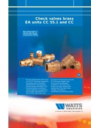
BACKFLOW PROTECTION DEVICES<br />
BA 909 DN 20 ( 3 ⁄4") through DN 50 (2")<br />
The solution: BA 909 backflow protector with air supply to the intermediate zone,<br />
equipped with a KIWA certificate in conformance with KIWA inspection<br />
guidelines BRL-K647.<br />
This solution means that now the BA 909, with KIWA certificate, can be used in<br />
even more cases as the interruption alternative advised by water companies.<br />
7<br />
An attractive alternative<br />
The BA 909 does not use any energy and the<br />
acquisition costs are considerably lower than<br />
those for an interruption unit.<br />
The BA 909 is appropriate for backflow and backsiphon<br />
cross connections.<br />
Intermediate zone<br />
Basic principle<br />
The BA 909 backflow protector offers complete<br />
<strong>protection</strong> of the water supply network against the<br />
danger of back-siphoning or backflow of<br />
contaminated water on the outlet side of the<br />
device. The BA 909 functions by maintaining a<br />
pressure level in the middle chamber (reduced<br />
pressure zone) that is lower than that on the<br />
inflow side of the device (see also operation).<br />
Figure 1 depicts the most serious situation that<br />
can occur in practice:<br />
• there is reverse pressure on the outlet side<br />
• there is under-pressure on the inflow side<br />
• neither check valve closes completely as the<br />
result of contamination.<br />
Inlet<br />
First<br />
check<br />
valve<br />
Relief valve<br />
Water out<br />
Air in<br />
Outlet<br />
Second check<br />
valve<br />
In this situation, under-pressure can also occur in<br />
the middle chamber, making it difficult or<br />
impossible for the backflow to be discharged.<br />
When this water reaches the first check valve, it<br />
can even be siphoned back into the water supply<br />
network. Thus, it is extremely important to<br />
prevent the occurrence of under-pressure in the<br />
middle chamber. The BA 909 achieves this by<br />
allowing air into the chamber via a separate<br />
channel that opens into the top of the chamber.<br />
A patent, U.S. patent no. 4.241.752 has been<br />
awarded for this so-called air-in/water-out<br />
principle.<br />
Figure 1<br />
Pressure-Temperature<br />
Appropriate for a maximum system pressure of 1000 kPa<br />
(10 bar) and for a maximum temperature of 60 °C. For<br />
higher temperatures a “hot water” model is available (max.<br />
90 °C) in dimensions from DN 20 through DN 50.<br />
Materials<br />
Bronze body, plastic seats for the check valves, other parts<br />
such as the relief valve with seat and stainless steel flange<br />
bolt, extended life rubber for the check valves and bronze<br />
test valves.<br />
Further technical specifications upon request.<br />
Dimensions<br />
Type Connection Dimensions Width Weight<br />
mm mm mm mm mm mm kg<br />
A B C D E<br />
BA 909 DN 20 3<br />
⁄4" 342 95 221 102 119 98 6.7<br />
BA 909 DN 25 1" 363 116 221 102 119 98 7.1<br />
BA 909 DN 32 1 1 ⁄4" 433 121 295 127 168 133 16.5<br />
BA 909 DN 40 1 1 ⁄2" 457 145 295 127 168 133 17.1<br />
BA 909 DN 50 2" 483 170 295 127 168 133 18.6<br />
B<br />
A<br />
D<br />
E<br />
C
BACKFLOW PROTECTION DEVICES<br />
8<br />
Operation<br />
The BA 909 backflow protector that<br />
provides air to the intermediate zone,<br />
provides complete <strong>protection</strong> of the<br />
water supply network against the<br />
danger of back-siphoning and/or<br />
backflow of contaminated water.<br />
In part due to the air chamber, the<br />
BA 909 offers optimum <strong>protection</strong><br />
based on the so-called air-in/water-out<br />
principle.<br />
kPa<br />
100<br />
90<br />
80<br />
70<br />
60<br />
DN 20<br />
50 0 0.08 0.16 0.24 0.32 0.40 0.48 0.56 0.64<br />
0 288 576 864 1152 1440 1728 2016 2304<br />
l/s<br />
l/h<br />
kPa<br />
100<br />
90<br />
80<br />
70<br />
DN 25<br />
60<br />
Water flow<br />
The first and the second check valve<br />
are opened so that water can flow<br />
through the device. The pressure in the<br />
water supply network against the<br />
diaphragm of the relief valve keeps the<br />
valve closed. The pressure in the<br />
middle chamber is a minimum of<br />
50 kPa lower than the water pressure.<br />
Static state<br />
Both check valves are now closed.<br />
Because the pressure on the inlet side<br />
is approximately 50 kPa higher than<br />
the pressure in the middle chamber,<br />
the relief valve is always kept closed.<br />
50 0 0.12 0.24 0.36 0.48 0.60 0.72 0.84 0.96<br />
0 432 864 1296 1728 2160 2592 3024 3456<br />
kPa<br />
100<br />
90<br />
80<br />
70<br />
60<br />
DN 32<br />
50 0 0.2 0.4 0.6 0.8 1.0 1.2 1.4 1.6<br />
0 720 1440 2160 2880 3600 4320 5040 5760<br />
kPa<br />
100<br />
90<br />
80<br />
70<br />
60<br />
DN 40<br />
l/s<br />
l/h<br />
l/s<br />
l/h<br />
50 0 0.3 0.6 0.9 1.2 1.5 1.8 2.1 2.4<br />
0 1080 2160 3240 4320 5400 6480 7560 8640<br />
kPa<br />
100<br />
90<br />
l/s<br />
l/h<br />
contamination<br />
80<br />
70<br />
60<br />
DN 50<br />
Back-siphoning<br />
When the pressure in the water supply<br />
network falls, both check valves close.<br />
The relief valve is opened and the<br />
water from the middle chamber is<br />
discharged via the water outlet. There<br />
is an atmospheric “interruption”<br />
between the water supply network and<br />
the contaminated or unknown water at<br />
the outlet side of the device.<br />
<strong>Backflow</strong><br />
When downstream backflow occurs,<br />
the first check valve closes and the<br />
water supply network is protected<br />
against backflow. Simultaneously the<br />
relief valve opens and discharges a<br />
quantity of water, so that the pressure<br />
in the middle chamber remains lower<br />
than the pressure in the water supply<br />
network. Because under normal<br />
circumstances the relief valve does not<br />
permit any water to flow through, water<br />
escaping from the relief valve is also a<br />
signal that something is wrong. When<br />
contamination occurs in the first and/or<br />
second check valve, in case of reverse<br />
pressure no backflow can take place<br />
because of the patented Watts airin/water-out<br />
principle.<br />
50 0 0.5 1.0 1.5 2.0 2.5 3.0 3.5 4.0 l/s<br />
0 1800 3600 5400 7200 9000108001260014400<br />
l/h<br />
Approvals<br />
The BA 909 backflow<br />
<strong>protection</strong> device has been<br />
certified by Kiwa in<br />
conformance with BRL-K647.<br />
“Adjustable backflow<br />
<strong>protection</strong> <strong>devices</strong> for backsiphon<br />
or reverse pressure<br />
cross connections, combined<br />
with air flow to the reduced<br />
pressure zone”. The approval<br />
has been recorded in KIWA<br />
certificate K 6086. The device<br />
has been tested and approved<br />
in the U.S.A. by various<br />
agencies including A.S.S.E.,<br />
A.W.W.A., C.S.A., U.C.F.,<br />
F.C.C.C.H.R. (California),<br />
S+A, U.L., U.P.C. and others.<br />
It has also been officially<br />
certified in various European<br />
countries (such as NF, KIWA<br />
and SVGW).
BACKFLOW PROTECTION DEVICES<br />
BA 909 DN 65 through DN 250 (2 1 ⁄2"-10")<br />
Pressure - Temperature<br />
Appropriate for a maximum system pressure of 1000 kPa (10 bar) and for a<br />
maximum temperature of 45 °C.<br />
9<br />
Material specifications<br />
Body:<br />
Check valve seats:<br />
Test valves:<br />
Relief valve:<br />
Relief valve stem:<br />
cast iron with epoxy coating<br />
bronze<br />
bronze<br />
bronze / cast iron with epoxy coating<br />
stainless steel<br />
Further technical specifications upon request.<br />
BA Unit<br />
A<br />
E<br />
D<br />
B<br />
C<br />
Dimensions<br />
Type Dimensions Weight Material Flanges<br />
mm mm mm mm mm kg number Bolt Bolt hole<br />
of bolts x pitch diameter<br />
bolt thread (mm) (mm)<br />
A B C D E (mm)<br />
BA 909 DN 65 664 178 133 229 102 51 cast iron 4 x M 16 145 18<br />
BA 909 DN 80 664 178 133 229 127 51 cast iron 8 x M 16 160 18<br />
BA 909 DN 100 940 241 152 346 152 111 cast iron 8 x M 16 180 18<br />
BA 909 DN 150 1130 368 152 346 241 211 cast iron 8 x M 20 240 22<br />
BA 909 DN 200 1403 470 248 470 267 379 cast iron 8 x M 20 298 22<br />
BA 909 DN 250 1715 546 248 470 298 565 cast iron 12 x M 20 356 22<br />
Flange boring in conformance with DIN 2532.<br />
Measurements subject to change without notice.<br />
kPa<br />
kPa<br />
kPa<br />
90<br />
90<br />
90<br />
80<br />
80<br />
80<br />
70<br />
DN 65<br />
70<br />
70<br />
DN 80 DN 100<br />
60<br />
60<br />
60<br />
50<br />
0 1.2 2.4 3.6 4.8 6.0 7.2 8.4 9.6<br />
0 4320 8640 12960 17280 21600 25920 30240 34560<br />
50<br />
l/s 0 2 4 6 8 10 12 14 16<br />
l/h 0 7200 14400 21600 28800 36000 43200 50400 57600<br />
50<br />
l/s 0 3 6 9 12 15 18 21 24<br />
l/h 0 10800 21600 32400 43200 54000 64800 75600 86400<br />
l/s<br />
l/h<br />
kPa<br />
kPa<br />
kPa<br />
90<br />
90<br />
90<br />
80<br />
80<br />
80<br />
70<br />
60<br />
DN 150 DN 200<br />
70<br />
60<br />
70<br />
60<br />
DN 250<br />
50<br />
0 7 14 21 28 35 42 49 56<br />
0 25200 50400 75600 100800 126000 151200 176400 201600<br />
50<br />
l/s 0 12 24 36 48 60 72 84 96<br />
l/h 0 43200 86400 129600 172800 216000 259200 302400 345600<br />
50<br />
l/s 0 20 40 60 80 100 120 140 160<br />
l/h 0 72000 144000 216000 288000 360000 432000 504000 576000<br />
l/s<br />
l/h
BACKFLOW PROTECTION DEVICES<br />
10<br />
Installation<br />
The BA 909 backflow protector must be<br />
installed so that it is easily accessible<br />
for maintenance and in order to verify<br />
that it is operating properly.<br />
It must be installed horizontally with a<br />
strainer on the inflow side of the BA<br />
909, in such a way as to protect the<br />
valves against unnecessary<br />
contamination. Moreover, a shut-off<br />
valve must be installed both upstream<br />
and downstream of the device in the<br />
water line. The overflow opening can<br />
be connected to the drain via an airgap<br />
tundish set.<br />
If installed without a drain, the device<br />
must be installed at a height of a<br />
minimum of 2 x DN ≥ 20 mm above the<br />
sink hole. This may only be installed<br />
after the pipe system has been cleaned<br />
in the normal method.<br />
Installation example<br />
Installing two <strong>devices</strong> in<br />
parallel makes it possible to<br />
perform maintenance<br />
properly without disrupting<br />
the water delivery.
BACKFLOW PROTECTION DEVICES<br />
Accessories<br />
Airgap tundish set 1717<br />
A type 1717 airgap tundish set can be used to mount a discharge pipe to the<br />
relief valve. This can be mounted directly to the body.<br />
The 1717 airgap tundish set is developed in conformance with NEN-EN 1717<br />
and EN 12729.<br />
The 1717 airgap tundish set can be easily connected to Ø 32 mm, 50 mm or<br />
75 mm discharges using PVC glue.<br />
11<br />
TK 9A Control Set<br />
The control set consists of a pressure differential manometer with modified<br />
connection hoses and nipples. Using this set, the installed protector can be<br />
regulated quickly and easily. The method described in the Watts TK9-A<br />
Operation and Control Methods Manual can be used as a guideline for this.<br />
BA <strong>Backflow</strong> <strong>protection</strong> <strong>devices</strong> must be checked regularly.<br />
A<br />
C<br />
B<br />
differential<br />
pressure gauge<br />
0<br />
0.25<br />
0.5<br />
BAR<br />
0.75<br />
1<br />
high pressure hose<br />
(yellow)<br />
low<br />
pressure<br />
hose<br />
(red)<br />
(blue)<br />
shutoff valve<br />
4<br />
test valves<br />
1<br />
2<br />
3<br />
shutoff valve<br />
5<br />
Open<br />
Closed
BACKFLOW PROTECTION DEVICES<br />
BA 009 DN 15 UP TO DN 80<br />
12<br />
Water companies demand assurance from all users that no contaminated or<br />
unknown water can siphon back into the drinking water network.<br />
To provide this assurance, Watts Industries provides backflow <strong>protection</strong> <strong>devices</strong><br />
in different <strong>protection</strong> categories.<br />
The BA 009 series (DN 15 - DN 80) is just one of the many possible versions.<br />
Inlet<br />
Intermediate zone<br />
Security of the drinking water<br />
The BA 009 backflow protectors with<br />
reduced pressure zone are specially<br />
designed to prevent drinking water<br />
contamination. They must be installed<br />
where there is a risk that contamination<br />
can occur due to back-siphoning or<br />
backflow.<br />
<strong>Backflow</strong> can occur because, as the<br />
result of a calamity, the pressure in a<br />
non-drinking water system temporarily<br />
exceeds that of the main water supply.<br />
Back-siphoning can arise if the network<br />
pressure falls below the original<br />
delivery pressure due to sudden<br />
extremely large consumption. In both<br />
cases contaminated water can flow<br />
back into the drinking water network,<br />
with all the risks that such an event<br />
entails.<br />
Outlet<br />
Basic principle of the BA 009<br />
(DN 15 - DN 80)<br />
The BA 009 <strong>protection</strong> device consists<br />
of two check valves connected in<br />
series, with a space between in which<br />
a relief valve is installed. The device<br />
operates by maintaining reduced<br />
pressure in this intermediate zone (see<br />
figure). Even if there is reverse<br />
pressure on the outlet side of the<br />
device and both check valves are<br />
contaminated, the device prevents<br />
contaminated water from entering the<br />
line. In such a situation, the relief valve<br />
will open and, in so doing, ensure<br />
atmospheric separation between the<br />
drinking water and the user network.<br />
The figure depicts this situation.<br />
Product features<br />
Easy to disassemble check valves:<br />
The first check valve, the second check<br />
valve and the relief valve are all quite<br />
simple to disassemble, which facilitates<br />
maintenance.<br />
Epoxy coating: The DN 65 & DN 80<br />
executions are coated with a highquality<br />
epoxy.<br />
First check valve<br />
Second check valve<br />
Relief valve<br />
BA 009 - pressure loss curves<br />
DN 15<br />
DN 20<br />
DN 25<br />
DN 32<br />
DN 40<br />
DN 50<br />
DN 65<br />
DN 80
BACKFLOW PROTECTION DEVICES<br />
Operation<br />
Traffic flow<br />
The first and the second check valve<br />
are open. The water pressure above<br />
the diaphragm of the relief valve keeps<br />
it closed. The pressure in the middle<br />
chamber is a minimum of 50 kPa lower<br />
than the outlet pressure.<br />
13<br />
Static state<br />
(no water being used)<br />
Both check valves are now closed.<br />
The pressure in the middle chamber<br />
remains 50 kPa lower than the outlet<br />
pressure, which keeps the relief valve<br />
closed.<br />
Back-siphoning<br />
When the pressure in the water supply<br />
network falls, both check valves close.<br />
The relief valve is opened and the<br />
water from the middle chamber is<br />
discharged via the water discharge<br />
outlet.<br />
An atmospheric 'interruption' is created<br />
between the water supply network and<br />
the contaminated or unknown water on<br />
the outlet side of the device.<br />
contamination<br />
<strong>Backflow</strong><br />
If back-pressure arises on the outlet<br />
side, reverse pressure is created and<br />
the first check valve closes, the relief<br />
valve opens and a quantity of water is<br />
discharged, so that the pressure in the<br />
middle chamber remains lower than<br />
that in the water supply network.<br />
Because under normal circumstances<br />
the relief valve does not permit any<br />
water to flow through, in addition to<br />
providing security, the escape of water<br />
through the relief valve serves as a<br />
signal that something is wrong.
BACKFLOW PROTECTION DEVICES<br />
Technical information<br />
14<br />
Installation dimensions DN 15 through DN 50<br />
Installation dimensions DN 65 & DN 80<br />
C B A<br />
G<br />
H<br />
E<br />
H<br />
G<br />
470<br />
245<br />
205<br />
D<br />
I<br />
F<br />
Type Art. no. A B C D E F G H I<br />
BA 009 DN15 405015010 45 50 95 35 110 205 G 1 ⁄2 14 138<br />
BA 009 DN20 405020010 45 45 80 60 140 305 G 3 ⁄4 14 225<br />
BA 009 DN25 405025010 45 45 80 60 140 305 G1 18 225<br />
BA 009 DN32 405032010 75 75115 90 225 455 G1 1 ⁄4 14 342<br />
BA 009 DN40 405040010 75 75115 90 225 455 G1 1 ⁄2 13 342<br />
BA 009 DN50 405050010 75 75115 90 235 470 G2 14 342<br />
115<br />
245<br />
Flange boring in conformance with DIN 2532.<br />
190<br />
Installation<br />
The BA 009 backflow protectors must be installed<br />
in such a way that they can be easily accessed<br />
for maintenance and to verify proper operation.<br />
The device must be installed horizontally with a<br />
strainer on the inlet side, in such a way as to<br />
protect the valves against unnecessary<br />
contamination (see installation examples).<br />
Moreover, shut-off valves must be installed<br />
upstream and downstream of the device in the<br />
water line.<br />
The relief opening can be connected to a drain<br />
via an airgap tundish set.<br />
If installed without at drain, the <strong>devices</strong> must be<br />
placed at a height of a minimum of 2 x DN ≥ 20<br />
mm above a sink hole. See installation examples.<br />
The device may not be installed until the pipe<br />
system has been cleaned using the customary<br />
method.<br />
System specifications<br />
Max. system pressure<br />
Max. water temperature<br />
PN 1000 kPa (10 bar)<br />
60 °C (standard)<br />
90 °C (upon request)<br />
Material specifications DN 15 t/m DN 50<br />
Body:<br />
bronze<br />
Check valve seats: plastic<br />
Rubber parts:<br />
silicon<br />
Seat relief valve:<br />
stainless steel<br />
Material specifications DN 65 & DN 80<br />
Body:<br />
cast iron with epoxy coating<br />
Flange boring:<br />
in conformance with<br />
DIN 2532 PN 10<br />
Other: idem as DN 15 through DN 50<br />
Approvals<br />
The BA 009 backflow <strong>protection</strong> device has been certified<br />
by KIWA in conformance with KIWA BRL-K646 (certificate<br />
number K 6117). The device has been tested and approved<br />
in the USA by the following agencies: ASSA, AWWA,<br />
FCCCHR and IAPMO. It has also been certified in various<br />
European countries (such as NF, KIWA and SVGW).
BACKFLOW PROTECTION DEVICES<br />
Installation examples<br />
<strong>Backflow</strong> protector<br />
Shut-off valve Type BA 009 Shut-off valve<br />
Strainer<br />
15<br />
<strong>Backflow</strong> protector<br />
Shut-off valve Type BA 009 Shut-off valve<br />
Strainer<br />
<strong>Backflow</strong> protector<br />
Shut-off valve Type BA 009 Shut-off valve<br />
Strainer
BACKFLOW PROTECTION DEVICES<br />
16<br />
BA BS Micro<br />
The BS Micro backflow <strong>protection</strong><br />
device is developed especially for low<br />
flow rate applications. This unique<br />
protector is used specifically in systems<br />
with a low flow. The device is<br />
especially appropriate for dental chairs<br />
and soap dispensers. The BS Micro<br />
offers optimum <strong>protection</strong> in<br />
conformance with liquids class 4.<br />
Standards<br />
The BA BS Micro was developed in<br />
conformance with EN1717.<br />
Installation guidelines<br />
Install the BA BS Micro in<br />
conformance with your national<br />
installation guidelines.<br />
BA<br />
Dimensions<br />
Pressure los curve<br />
36<br />
143<br />
Delta P[kPa]<br />
160<br />
140<br />
A<br />
A<br />
120<br />
110.5<br />
100<br />
80<br />
ø32<br />
DN Model A<br />
6 BS006 1<br />
⁄8"<br />
8 BS008 1<br />
⁄4"<br />
10 BS010 3<br />
⁄8"<br />
60<br />
40<br />
20<br />
0<br />
0 0,2 0,4 0,6 0,8 1 1,2 1,4<br />
Flow (m 3 /h)<br />
BS006 BS008 BS010 EN 12729 DN6 EN 12729 DN8 EN 12729 DN10<br />
Putting the device<br />
into operation<br />
Put the BS Micro into<br />
operation by opening the<br />
shut-off valve up- and<br />
downstream of the device.<br />
Then open the test cocks to<br />
bleed the device.<br />
After retightening the valves,<br />
the device is ready to<br />
operate.<br />
Checking the device<br />
According to the national<br />
standard, backflow <strong>protection</strong><br />
<strong>devices</strong> must be checked at<br />
least once a year.<br />
Installation<br />
Install the BS Micro after cleaning the pipe system.<br />
To prevent contaminated water from flowing back into the potable water system,<br />
the BS Micro is installed upstream of the <strong>devices</strong>. Install the device in an easily<br />
accessible place: this simplifies inspections and maintenance.<br />
Ensure that the device is installed horizontally and is not under tension. Place a<br />
strainer on the inlet side of the device: this protects the valves against<br />
unnecessary contamination. Moreover, shut-off valves are installed both<br />
upstream of the strainer and downstream of the device. The discharge vent can<br />
be connected to a drain via the integrated funnel.<br />
Material specifications<br />
Body<br />
Brass (DZR)<br />
Check valve Polymer<br />
Sealing<br />
Rubber<br />
Spring<br />
Stainless steel<br />
Funnel<br />
Polymer<br />
Technical specifications<br />
Connection DN6 1<br />
⁄8"<br />
Connection DN8 1<br />
⁄4"<br />
Connection DN10 3 ⁄8"<br />
Lenght x height 143 mm x 110,5 mm<br />
Operating pressure PN 10<br />
Max. temperature 65 °C<br />
Approvals<br />
DVGW<br />
NF<br />
Other approvals in progress
BACKFLOW PROTECTION DEVICES<br />
CA 9C<br />
The CA 9C offers a simple and an<br />
efficient <strong>protection</strong> against pollution of<br />
the drinking water supply system.<br />
This <strong>protection</strong> device prevents<br />
backflow of polluted water from flowing<br />
back into the drinking water supply<br />
system (fluid class 3). The CA 9C has<br />
a double non-return valve construction<br />
with an intermediate relief valve and<br />
offers <strong>protection</strong> with regard to backsiphoning<br />
as well as backflow.<br />
The CA 9C was especially developed<br />
for smaller connections to the water<br />
supply system.<br />
Standardization<br />
The CA 9C <strong>protection</strong> device has been<br />
developed in conformity with EN1717.<br />
Installation instructions<br />
Install the CA 9C <strong>protection</strong> device<br />
according to national installation<br />
instructions.<br />
CA<br />
17<br />
Strainer<br />
First check valve<br />
Diaphragm<br />
Discharge opening<br />
Seat<br />
Second check valve<br />
Water flow<br />
The pressure in the water supply network ensures<br />
that the diaphragm keeps the discharge opening<br />
closed; then the first check valve is released from<br />
the diaphragm. The water flows to the second<br />
check valve via the middle chamber and lifts it<br />
from its seat.<br />
Static state<br />
Both check valves are now closed. The discharge<br />
opening is always held closed.<br />
Back-siphoning<br />
When the pressure in the water supply network<br />
falls, the second check valve closes against the<br />
seat. The first check valve closes against the<br />
diaphragm, the discharge opening opens to the<br />
intermediate zone, once enough overpressure is<br />
created. This creates an atmospheric<br />
"interference" between the water supply network<br />
and the contaminated water downstream. If the<br />
check valve is contaminated, seepage is<br />
discharged via the opening. This prevents<br />
contamination of the drinking water.
BACKFLOW PROTECTION DEVICES<br />
Dimensions<br />
Pressure loss curve DN 15 and DN 20<br />
18<br />
Ø 40 mm<br />
Debit / debiet Flow mM 3 /H /h<br />
Article number Item L H Weight<br />
A Ø<br />
mm mm kg.<br />
407015290 CA 9C 1 ⁄2" bi x bi* 121 129 0,59<br />
407020290 CA 9C 3 ⁄4" bi x bi* 151 129 0,66<br />
* device is supplied incl. funnel set<br />
Operation<br />
You can start to use the CA 9C by<br />
slowly opening the stop cock for the<br />
CA 9C.<br />
Inspection<br />
According to national standards a CA<br />
backflow <strong>protection</strong> device must be<br />
inspected at least once a year.<br />
Functional tests<br />
It is possible to test the CA 9C to see<br />
whether it functions correctly.<br />
Assembly<br />
Assemble the CA 9C after the water supply system has been cleaned<br />
in the prescribed way. Install the CA 9C in front of the dangerous<br />
appliance. This prevents polluted water from flowing back into the<br />
drinking water system. Install the CA 9C horizontally and when the<br />
system is dead.<br />
The integrated filter on the inlet side of the device sees to it that the<br />
non-return valves and relief valve are protected against unnecessary<br />
pollution. Regularly clean this filter.<br />
In conformity with the national installation instructions, a stop cock (1)<br />
with draining device (2) must be placed in front of the CA 9C. The<br />
relief opening must be connected to a discharge pipe via the enclosed<br />
funnel.<br />
1<br />
2<br />
Material specifications<br />
Body Brass (DZR)<br />
Spring Stainless steel<br />
Sealing Rubber<br />
Funnel Plastic<br />
Technical specifications<br />
Diameter nominal DN 15, DN 20<br />
Connection F 1 ⁄2", 3 ⁄4"<br />
Working pressure PN 10<br />
Max. temperature 65 °C<br />
Connection tundish Ø 40 mm<br />
Approvals<br />
BELGAQUA<br />
KIWA<br />
SVGW<br />
NF<br />
WRAS
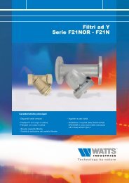
BACKFLOW PROTECTION DEVICES<br />
DA 288A(C)<br />
Anti-siphon vacuum breaker<br />
Anti-siphon vacuum breakers prevent backflow caused by contaminated water<br />
being siphoned back into the drinking water network.<br />
19<br />
DA 288A<br />
Anti-siphon <strong>devices</strong> with atmospheric vent prevent back caused by contaminated<br />
water being siphoned back into the drinking water network. One distinctive<br />
characteristic of these atmospheric vents is the lightweight valve, which is<br />
appropriate for temperatures up to 90 °C, that closes the vent opening, thus<br />
preventing water from escaping.<br />
Application<br />
DA 288A is also recommended for equipment with<br />
small tap capacities, such as lab equipment, for<br />
example. In drinking water installations to<br />
equipment in which the water supply runs below<br />
the overflow level. In such a situation, the device<br />
is installed downstream of the shut-off valve, and<br />
is thus not under constant pressure.<br />
No shut-off device can be placed downstream of<br />
the DA.<br />
Advantages<br />
1. Silicon rubber seal<br />
2. Bearing<br />
3. Large flow-through for maximum capacity and<br />
minimum resistance<br />
4. Lightweight valve<br />
Model/dimensions<br />
DA 288A connection sizes 1 ⁄4" through 3" in bronze<br />
DA 288AC connection sizes 1 ⁄4" through 1" in<br />
chromed bronze (polished)<br />
C<br />
B<br />
1<br />
A<br />
2<br />
4<br />
Max. pressure.: 10 bar<br />
Max. temp.: 90 °C<br />
Further technical specifications upon request.<br />
3<br />
Dimensions<br />
min.<br />
300 mm<br />
Type Connection A B C Weight<br />
mm mm mm kg<br />
DA 288A(C) 1 ⁄4" 43 27 30 0.17<br />
DA 288A(C) 3 ⁄8" 43 27 30 0.17<br />
DA 288A(C) 1 ⁄2" 51 30 37 0.23<br />
DA 288A(C) 3 ⁄4" 57 38 41 0.51<br />
DA 288A(C) 1" 73 43 54 0.80<br />
DA 288A 1 1 ⁄4" 73 46 54 0.97<br />
DA 288A 1 1 ⁄2" 92 56 62 1.64<br />
DA 288A 2" 105 64 73 2.38<br />
DA 288A 2 1 ⁄2" 162 76 111 7.26<br />
DA 288A 3" 162 86 118 7.77
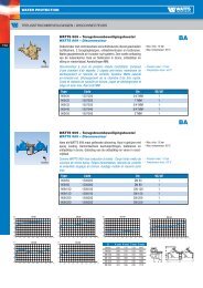
BACKFLOW PROTECTION DEVICES<br />
20<br />
EA & EB check valves<br />
Watts Industries brass and cast iron check valves<br />
prevent back-siphoning of potable water or water<br />
of unknown quality. The drain and regulation<br />
options allow you to check the operation of the<br />
device and its imperviousness to leaks without<br />
disassembling the check valve. The brass and<br />
cast iron check valves can be applied in<br />
both interior applications and other EA<br />
applications.<br />
Standardization<br />
The controllable check valves<br />
EA has been developed in<br />
conformity with EN 1717.<br />
Installation instructions<br />
Install the check valves EA<br />
according to national<br />
installation instructions.<br />
Special characteristics<br />
KIWA, DVGW, NF and/or BELGAQUA approvals<br />
Complies with the CEN-norm EN 13959<br />
Safety class EA<br />
Very low resistance<br />
Long life<br />
Hammer-free operation<br />
Noise-free operation<br />
Materials<br />
Body<br />
brass<br />
Plugs<br />
brass or plastic<br />
Nuts<br />
brass<br />
Connection unions brass<br />
Check valve plastic<br />
Seal<br />
rubber SBR<br />
Pressure spring stainless steel<br />
Model<br />
The check valve consists of:<br />
Brass body with test and drain ports<br />
Nuts and connection unions, as required<br />
Plastic check valve module<br />
Lipseal sealing principle<br />
Split valve stem<br />
Technical data<br />
Width range DN 15 - DN 65<br />
Connection sizes<br />
1<br />
⁄2" through 3" or 15 mm<br />
through 67 mm<br />
Test ports 1<br />
⁄4"<br />
Operational temperature 65 °C (max. 90 °C)<br />
Nominal pressure PN 10<br />
Max. operating pressure 1600 kPa (16 bar)<br />
Application area<br />
Liquids:<br />
drinking water<br />
EA check valves<br />
Type Nominal Connection sizes Total Approvals ifBt- Weight<br />
width length mark kg<br />
DN Inlet and outlet mm<br />
MU Chromed Male and female<br />
15 1<br />
⁄2" x 1 ⁄2" 47 KIWA 0.10<br />
20 3<br />
⁄4" x 3 ⁄4" 56 KIWA 0.17<br />
S Male to male<br />
15 3<br />
⁄4" x 3 ⁄4" 66 KIWA/DVGW/NF P-IX724/I 0.12<br />
20 1" x 1" 77 KIWA/DVGW/NF P-IX724/I 0.17<br />
25 1 1 ⁄4" x 1 1 ⁄4" 80 KIWA/DVGW/NF P-IX724/I 0.37<br />
32 1 1 ⁄2" x 1 1 ⁄2" 90 KIWA/DVGW/NF P-IX724/I 0.55<br />
40 2" x 2" 100 KIWA/DVGW/NF 0.84<br />
50 2 1 ⁄2" x 2 1 ⁄2" 115 KIWA/DVGW/NF 1.21<br />
PS Soldered connection unions<br />
15 connection unions Ø 15 97 KIWA/DVGW P-IX724/I 0.24<br />
20 connection unions Ø 22 120 KIWA/DVGW P-IX724/I 0.35<br />
25 connection unions Ø 28 128 KIWA/DVGW P-IX724/I 0.67<br />
32 connection unions Ø 35 148 KIWA/DVGW P-IX724/I 0.95<br />
40 connection unions Ø 42 166 KIWA/DVGW 1.51<br />
50 connection unions Ø 54 199 KIWA/DVGW 2.27<br />
65 connection unions Ø 67 225 3.42<br />
PU Male to female<br />
15 1<br />
⁄2" x 1 ⁄2" 137 KIWA/DVGW P-IX724/I 0.30<br />
20 3<br />
⁄4" x 3 ⁄4" 156 KIWA/DVGW P-IX724/I 0.44<br />
25 1" x 1" 169 KIWA/DVGW P-IX724/I 0.78<br />
32 1 1 ⁄4" x 1 1 ⁄4" 185 KIWA/DVGW P-IX724/I 1.17<br />
40 1 1 ⁄2" x 1 1 ⁄2" 202 KIWA/DVGW 1.74<br />
50 2" x 2" 241 KIWA/DVGW 2.65<br />
65 3" x 3" 125 1.57
BACKFLOW PROTECTION DEVICES<br />
EA check valves<br />
Type Nominal Connection sizes Total Approvals ifBt- Weight<br />
width length mark kg<br />
DN Inlet and outlet mm<br />
PI Female to female<br />
10 3<br />
⁄8" x 3 ⁄8" 101 KIWA/DVGW P-IX724/l 0.27<br />
15 1<br />
⁄2" x 1 ⁄2" 120 KIWA/DVGW P-IX724/I 0.30<br />
20 3<br />
⁄4" x 3 ⁄4" 120 KIWA/DVGW P-IX724/I 0.44<br />
25 1" x 1" 124 KIWA/DVGW P-IX724/I 0.67<br />
32 1 1 ⁄4" x 1 1 ⁄4" 160 KIWA/DVGW P-IX724/I 1.23<br />
40 1 1 ⁄2" x 1 1 ⁄2" 187 KIWA/DVGW 1.85<br />
50 2" x 2" 187 KIWA/DVGW 2.46<br />
WF Nut to male<br />
15 3<br />
⁄4" x 3 ⁄4" 88 KIWA/NF 0.16<br />
20 1" x 1" 92 KIWA/NF 0.25<br />
25 1 1 ⁄4" x 1 1 ⁄4" 113 KIWA/NF 0.43<br />
32 1 1 ⁄2" x 1 1 ⁄2" 115 KIWA/NF 0.60<br />
40 2" x 2" 120 KIWA/NF 0.85<br />
50 2 1 ⁄2" x 2 1 ⁄2" 135 KIWA/NF 1.50<br />
WH Nut to male<br />
15 3<br />
⁄4" x 3 ⁄4" 60 x 40 KIWA/NF 0.22<br />
20 1" x 1" 67 x 48 KIWA/NF 0.31<br />
FC Flange connector<br />
(60) 65 flanges PN 10 290 Belgaqua/DVGW/NF<br />
80 flanges PN 10 310 Belgaqua/DVGW/NF<br />
100 flanges PN 10 350 Belgaqua/DVGW/NF<br />
Bigger sizes on request<br />
KF Compression ends<br />
15 for pipe size 15 mm 90 KIWA 0.16<br />
20 for pipe size 22 mm 89 KIWA 0.22<br />
BB<br />
25 for pipe size 28 mm 92 KIWA 0.35<br />
Female to female<br />
15 1<br />
⁄2" x 1 ⁄2" 66 Belgaqua/NF 0.13<br />
20 3<br />
⁄4" x 3 ⁄4" 76 Belgaqua/NF 0.20<br />
25 1" x 1" 91 Belgaqua/NF 0.35<br />
32 1 1 ⁄4" x 1 1 ⁄4" 111 KIWA/Belgaqua/NF 0.60<br />
40 1 1 ⁄2" x 1 1 ⁄2" 121 KIWA/Belgaqua/NF 0.80<br />
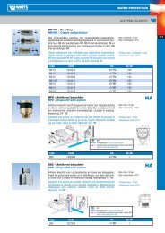
50 2" x 2" 151 KIWA/Belgaqua/NF 1.50<br />
CC 55.1 Compression ends<br />
15 for pipe size 15 mm 140 KIWA 0.50<br />
20 for pipe size 22 mm 165 KIWA 0.75<br />
CC<br />
Compression ends<br />
15 for pipe size 15 mm 140 KIWA 0.45<br />
20 for pipe size 22 mm 165 KIWA 0.70<br />
55.1 Male to male<br />
15 1<br />
⁄2" x 1 ⁄2" KIWA/DVGW 0.50<br />
20 3<br />
⁄4" x 3 ⁄4" KIWA/DVGW 0.70<br />
25 1" x 1" KIWA/DVGW 1.30<br />
21
BACKFLOW PROTECTION DEVICES<br />
EB check valves<br />
22<br />
Type Flow Ø Total length Approvals Weight<br />
Inch mm mm kg<br />
NN Male to female, chrome plated<br />
1<br />
⁄2" 15 1<br />
⁄2" x 1 ⁄2" 28 KIWA/BELGAQUA 0.05<br />
3<br />
⁄4" 20 3<br />
⁄4" x 3 ⁄4" 33 KIWA/BELGAQUA 0.10<br />
NR Female to female, chrome plated<br />
1<br />
⁄2" 15 1<br />
⁄2" x 1 ⁄2" 30 KIWA/BELGAQUA 0.05<br />
3<br />
⁄4" 20 3<br />
⁄4" x 3 ⁄4" 36 KIWA/BELGAQUA 0.09<br />
NW Female to female, chrome plated<br />
1<br />
⁄2" 15 3<br />
⁄4" x 1 ⁄2" 30 KIWA 0.07<br />
Watts Industries brass check valves resistance graph<br />
Pressure differential [kPa]<br />
100<br />
10<br />
1<br />
2<br />
3<br />
4<br />
5<br />
6<br />
1<br />
0,1 1 10 100 1000<br />
Volume flow [l/min]<br />
Global values, specific curves per valve available upon request.<br />
Line Check valve<br />
no. type<br />
1 BB015 KF015<br />
2 BB020 KF020 S015 WF015<br />
3 BB025 KF025 S020 WF020<br />
4 BB032 S025 WF025<br />
S032 WF032<br />
5 BB040 S040 WF040<br />
6 BB050 S050 WF050
BACKFLOW PROTECTION DEVICES<br />
EA FC controllable anti-pollution check valve<br />
This flanged controllable Anti-Pollution Check Valve is dedicated to be installed<br />
as a <strong>Backflow</strong> Prevention Device (code EN1717:EA) in potable water installations<br />
and other sanitary applications. This device can also be used in processes like<br />
distribution networks and pump installations.<br />
23<br />
Benefits of the EA FC check valve:<br />
- Construction and performance in compliance with national standards and<br />
European standard EN 13959<br />
- Compact construction<br />
- Standardized length<br />
- Modular check valve cartridge for fast and easy maintenance<br />
- No internal parts to be lost while replacing the cartridge<br />
- Low pressure loss<br />
- Ranging from DN 65 (DN60) up to DN 100 inclusive and according to DIN PN16<br />
(bigger sizes on request)<br />
Pressure loss curve FC065, FC080, FC100<br />
Delta P [kPa]<br />
45<br />
40<br />
35<br />
30<br />
25<br />
20<br />
Capacity [m 3 /h]<br />
15<br />
10<br />
5<br />
0<br />
0 20 40 60 80 100 120 140<br />
Flow [m 3 /h]<br />
CEN DN65 CEN DN80 CEN DN100 FC065 FC080 FC100
BACKFLOW PROTECTION DEVICES<br />
24<br />
Technical specifications<br />
Nominal flow 60 up to 250 mm<br />
Operating pressure max. 16 bar<br />
Test pressure max. 24 bar<br />
Max. temperature 65 °C<br />
Material specifications<br />
Body / cover ductile iron GGG40<br />
Coating Epoxy Coated, RAL 5015<br />
Polymer parts PPO / PP<br />
Rubber parts NBR<br />
Approvals<br />
ACS<br />
Belgaqua<br />
DVGW<br />
KIWA<br />
NF<br />
WRAS<br />
Dimensions<br />
A<br />
C<br />
E<br />
D<br />
CV<br />
F<br />
B<br />
B<br />
C<br />
B<br />
G<br />
H<br />
Article number Type DN CV A B C D E F G H<br />
308065361 FC065 (60) 65 CS100 290 G1/2 145 37.5 185 118 (135) 145 4 x 19<br />
308080361 FC080 80 CS100 310 G1/2 155 44 200 132 160 8 x 19<br />
308100361 FC100 100 CS100 350 G1/2 175 64 220 156 180 8 x 19
BACKFLOW PROTECTION DEVICES<br />
HA S8C/NF8 hose union backflow preventer<br />
Anti-siphon <strong>devices</strong> with atmospheric vent for hand-held showers and spigots for<br />
hose connections that are mounted downstream of the shut-off valve so that they<br />
are not under continual pressure.<br />
25<br />
HA S8C<br />
HA S8C is an anti-siphon device with atmospheric vent for<br />
hand-held showers that are mounted downstream of the<br />
shut-off valve, so that they are not under continual<br />
pressure.<br />
31<br />
1 2"<br />
Model: brass chrome plated (polished)<br />
Max. pressure: 10 bar<br />
Max. temp.: 60 °C<br />
37<br />
Measurements subject to change without notice.<br />
Further technical specifications upon request.<br />
1<br />
2"<br />
Operation<br />
3<br />
2<br />
1<br />
3<br />
1<br />
2<br />
3<br />
2<br />
1<br />
HA S8C in closed position.<br />
Valve 1 closes against<br />
diaphragm 2. Openings 3 to<br />
the atmosphere are open.<br />
Before flow starts, openings<br />
3 are closed.<br />
Only then valve 1 opens.<br />
As the result of the loss of<br />
pressure in the network,<br />
valve 1 closes against<br />
diaphragm 2, preventing any<br />
backflow. Ports 3 are<br />
opened.<br />
HA NF8<br />
HA NF8 hose union backflow preventers are used with taps<br />
for hose connections and must be installed in a vertical<br />
position. HA NF8 is constructed using a shear screw, which<br />
means that it cannot be removed. When the ring is pressed<br />
down on the outside, in such a way as to prevent freezing of<br />
the tap and the atmospheric vent, the hose connected to it<br />
can be tapped. This is mounted downstream of the shut-off<br />
valve, and is thus not under continual pressure. Height ><br />
200 mm above the maximum downstream fluid level.<br />
Model:<br />
brass<br />
Max. pressure: 10 bar<br />
Max. temp.: 60 °C<br />
Operation: same as the HA S8C<br />
Further technical specifications available upon request.<br />
38<br />
3 4"<br />
3 4"<br />
51
BACKFLOW PROTECTION DEVICES<br />
HD N9/NLF9 hose union anti-vacuum valve<br />
combined with a check valve<br />
26<br />
HD N9/NLF9, dual check valves with atmospheric vents with intermediate<br />
atmospheric connection.<br />
HD N9/NLF9<br />
HD N9/NLF9 prevents back-siphoning of contaminated<br />
water into the drinking water network and is appropriate for<br />
laboratory use. HD N9/NLF9 must be installed vertically.<br />
The construction is identical to that of the HA S8C/NF8;<br />
however, a second check valve is installed on the outlet<br />
side. HD N9 is appropriate for mounting under continual<br />
pressure. HD NLF9 is appropriate for mounting downstream<br />
of the shut-off valve. The downstream piping, which is not<br />
under constant pressure, must be flexible and detachable.<br />
31<br />
Model:<br />
HD NLF9 brass chrome plated (polished)<br />
HD N9 brass<br />
Max. pressure: 10 bar<br />
Max. temp.: 60 °C<br />
25<br />
32<br />
Operation<br />
1. Static position, no water<br />
flow.<br />
2. Water flow, both valves<br />
are opened.<br />
3. Back-siphoning, both<br />
valves are closed.<br />
HD NLF9<br />
Connection sizes:<br />
HD NLF9: 3<br />
⁄8" female thread x 3 ⁄8" male thread<br />
HD N9: 1<br />
⁄4" female thread x 1 ⁄4" female thread<br />
HD N9: 3<br />
⁄8" female thread x 3 ⁄8" female thread<br />
H > 200 mm<br />
Further technical specifications upon request.<br />
Discharge<br />
Afvoer
BACKFLOW PROTECTION DEVICES<br />
Terms and definitions<br />
For the purpose of this European<br />
standard, the following terms and<br />
definitions apply.<br />
Air break to drain<br />
The unobstructed distance between<br />
the low point of overflow, discharge or<br />
drain of a device or installation,<br />
leading from a water apparatus, and<br />
the top point of the device which<br />
collects this water.<br />
Air gap<br />
The physical break between the lowest<br />
level of the water inlet and the<br />
maximum fault level or critical level of<br />
an appliance or installation, a feed<br />
pipe, or an air inlet orifice incorporated<br />
into a hydraulic circuit.<br />
Air inlet<br />
An orifice designed to admit air from<br />
the atmosphere into a hydraulic circuit.<br />
offices, communal residences, etc.<br />
(for example kitchen sink, wash and<br />
handbasin, bath, shower, WC,<br />
production of hot water for sanitary<br />
purposes, domestic washing machine<br />
and dishwasher, bidet, watering of<br />
garden);<br />
- special uses relating to similar<br />
consumers where products are used<br />
with low concentrations and<br />
presenting no danger for human<br />
health (for example authorised water<br />
conditioning, air conditioning);<br />
- in industrial and commercial<br />
premises “Domestic use” is limited to<br />
water used for those<br />
applications/appliances described<br />
under normal use in dwelling and<br />
homes (for example excludes water<br />
used for process, fire fighting, central<br />
heating or irrigation systems).<br />
Downstream<br />
The side to which fluid flows under<br />
normal conditions.<br />
LD50<br />
The quantities of substances<br />
or mixture which, given on<br />
one intake through oral and<br />
parental path, bring about<br />
within 15 days (the required<br />
time to take into account<br />
potential delayed effect) the<br />
death of 50 out of 100<br />
treated animals.<br />
Non domestic use<br />
All uses related to a<br />
professional activity within<br />
industry, trade, agriculture,<br />
health establishments, etc.<br />
All uses related to pricate<br />
and public swimming pools<br />
and public baths.<br />
Overflow<br />
A means for discharging<br />
naturally excess fluid from an<br />
appliance when it has<br />
reached a specified level.<br />
27<br />
Appliance, equipment<br />
A device in which the potable water is<br />
used and/or is modified e.g. water<br />
heater, chemical dosing unit, coffeemachine,<br />
WC-pan.<br />
<strong>Backflow</strong><br />
Movement of the fluid from<br />
downstream to upstream within an<br />
installation.<br />
<strong>Backflow</strong> <strong>protection</strong> device<br />
A device which is intended to prevent<br />
contamination of potable water by<br />
backflow.<br />
Contamination<br />
Result of rendering impure by contact<br />
or mixture, to corrupt, defile, pollute,<br />
sully, taint or infect.<br />
Disconnection<br />
Break in a hydraulic circuit creating an<br />
atmospheric area between two<br />
elements, one carrying or containing<br />
potable water (upstream) and another<br />
carrying or containing another fluid<br />
(downstream).<br />
Domestic use<br />
Any use related to residential or similar<br />
dwellings:<br />
- normal use for dwellings and homes,<br />
as well as hotels, schools and<br />
Potable water system<br />
Water system located downstream of<br />
the delivery point specified by the<br />
water supply authorities or regulations.<br />
Family of <strong>protection</strong><br />
General identification of a backflow<br />
<strong>protection</strong> device principle.<br />
Fluid<br />
All substances which can be deformed<br />
by small forces. Fluids are divided into<br />
liquids and gases.<br />
Liquid levels<br />
Critical level<br />
Physical or piezometric level of the<br />
liquid reached in any part of the<br />
appliance 2 s after closing the water<br />
inlet, starting from maximum fault<br />
level.<br />
Maximum operational level<br />
In an open system, this is the<br />
maximum level of the liquid. In a<br />
pressurized system, this is the<br />
maximum piezometric height possible.<br />
Maximum fault level<br />
The highest physical or piezometric<br />
level of the liquid reached in any part<br />
of the appliance when it operates<br />
continuously under fault conditions as<br />
described in product standard.<br />
Point of use<br />
The point where water is<br />
drawn by the user either<br />
directly or by connecting an<br />
apparatus.<br />
Pollution of potable<br />
water<br />
Any degradation of the<br />
quality of potable water.<br />
Protection point<br />
Location in a hydraulic circuit<br />
where a <strong>protection</strong> unit is<br />
installed.<br />
Protection unit<br />
A device or a device in<br />
combination with other<br />
hydraulic components which<br />
constitutes the <strong>protection</strong><br />
against backflow.<br />
Type of <strong>protection</strong><br />
An identified operating<br />
principle applied to a<br />
<strong>protection</strong> device belonging<br />
to a given family.<br />
Upstream<br />
The side from which fluid<br />
flows under normal<br />
circumstances.<br />
The photos and description contained in this brochure are solely intended as an indication, Watts Industries<br />
reserves the right to make technical and design changes to its products without prior notice.
Product range Watts Industries<br />
- System Disconnectors<br />
- <strong>Backflow</strong> Protection Devices<br />
- Check Valves<br />
- Safety Units<br />
- Safety Relief Valves<br />
- Pressure Reducing Valves<br />
- Automatic Control Valves<br />
- Butterfly Valves<br />
- Shut-Off Valves<br />
- Measuring Gauges<br />
- Temperature Control<br />
- Expansion Vessels<br />
- Process Switches<br />
- Fuel Products<br />
- Gas Products<br />
- Electronic Controls<br />
- Installation Protection Products<br />
- Radiator Valves<br />
- System Products<br />
- Manifolds and Fittings<br />
Watts Industries Netherlands B.V.<br />
Kollergang 14, 6961 LZ Eerbeek, The Netherlands<br />
Phone +31 313 673 700 - Fax +31 313 652 073<br />
E-mail info@watts<strong>industries</strong>.nl - Site www.watts<strong>industries</strong>.com<br />
50-NL-UK-07/07