A Real-Time PC-Based Software Radio DVB-T Receiver - Wseas
A Real-Time PC-Based Software Radio DVB-T Receiver - Wseas
A Real-Time PC-Based Software Radio DVB-T Receiver - Wseas

Create successful ePaper yourself
Turn your PDF publications into a flip-book with our unique Google optimized e-Paper software.
WSEAS TRANSACTIONS on COMMUNICATIONS<br />
Shu-Ming Tseng, Jian-Cheng Yu, Yueh-Teng Hsu<br />
A <strong>Real</strong>-<strong>Time</strong> <strong>PC</strong>-<strong>Based</strong> <strong>Software</strong> <strong>Radio</strong> <strong>DVB</strong>-T <strong>Receiver</strong><br />
Shu-Ming Tseng Jian-Cheng Yu Yueh-Teng Hsu<br />
Department of Electronic Engineering<br />
National Taipei University of Technology<br />
1, Sec. 3, Chung-hsiao E. Rd., Taipei,10608,Taiwan, R.O.C.<br />
Taipei, Taiwan<br />
shuming@ntut.edu.tw http://www.cc.ntut.edu.tw/~shuming/<br />
Abstract: - We propose a <strong>PC</strong>-based real-time software Digital Video Broadcasting-Terrestrial (<strong>DVB</strong>-T)<br />
receiver, including hardware, driver, and software parts. The total data rate of <strong>DVB</strong>-T is much greater than that<br />
of Digital Audio Broadcasting (DAB). A more efficient signal processing algorithm than our previous software<br />
DAB receiver is necessary to improve the speed of the software part of the <strong>DVB</strong>-T receiver. Therefore, we<br />
propose some modifications in software: Viterbi algorithm optimization, and Digital-Down-Converter (DDC)<br />
optimization. Finally, it only takes 1541 ms to decode the 2760ms video data in this system, and the data<br />
recoded at 100km/hr vehicle speed is successfully decoded.<br />
Key-Words: - software radio, mobility, Digital Video Broadcasting, orthogonal frequency-division multiplexing<br />
1 Introduction<br />
The most important benefit of <strong>Software</strong> <strong>Radio</strong><br />
(SR) research, when compared with hardware radio,<br />
is that people can modify and change the signal<br />
processing procedure, the algorithm, and the result<br />
can be easily tested. Hence, more efficient detection<br />
or estimation algorithms are proposed with software<br />
language to improve the performance of a radio<br />
receiver rather than producing a new ASIC chip.<br />
The <strong>PC</strong>-based SR example includes a software<br />
Global Position System (GPS) [1] and software<br />
Digital Audio Broadcasting (DAB) capability [2].<br />
The SR receivers, which are <strong>PC</strong>-based, are more<br />
suitable for research and as a development platform<br />
than the conventional hardware.<br />
The total data rate of DAB is 2.4 Mbps<br />
(DQPSK); Digital Video Broadcasting-Terrestrial<br />
(<strong>DVB</strong>-T) is 9.953 Mbps (16 QAM, guard interval<br />
1/4, rate 2/3 convolutional code, non-hierarchical<br />
system for 6 MHz channels) [3]. The data rate of<br />
<strong>DVB</strong>-T is much greater than the data rate of DAB.<br />
The software Viterbi decoder needs to be<br />
implemented faster due to much higher data rate<br />
than the DAB system [4]. The Reed-Solomon (RS)<br />
code is an additional feature in <strong>DVB</strong>-T, and already<br />
optimized in another journal paper [5]. The<br />
performance of the RS and Viterbi decoder is<br />
improved by several methods: (1) use the new<br />
SIMD instructions; (2) modify the program to<br />
reduce the branch; and (3) have more efficient and<br />
useful procedures.<br />
In addition, we also propose new Digital Down<br />
Converter (DDC) to combine the mixer and filter<br />
operations to enhance the decoding speed in the<br />
software <strong>DVB</strong>-T receiver. We also implemented the<br />
hardware and driver necessary to construct a<br />
complete software <strong>DVB</strong>-T receiver.<br />
This paper is organized as follows. First we<br />
describe the previous SR in Section 1. The system<br />
model block diagram is introduced in Section 2. The<br />
proposed system hardware is described in detail in<br />
Section 3. The driver is described in Section 4. The<br />
software is described in Section 5. Implementation<br />
and results are described in Section 6. Section 7<br />
presents the conclusions.<br />
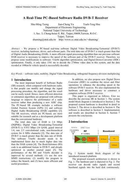
2 Introduction<br />
Fig. 1 System model block diagram of the<br />
introduced research platform<br />
The proposed research architecture is shown in<br />
Fig. 1. The hardware part is depicted in Fig. 2. The<br />
receiver can decode radio signals and record<br />
baseband signals into the hard disk continuously.<br />
E-ISSN: 2224-2864 281 Issue 6, Volume 12, June 2013
WSEAS TRANSACTIONS on COMMUNICATIONS<br />
Shu-Ming Tseng, Jian-Cheng Yu, Yueh-Teng Hsu<br />
The A/D chip and Low Voltage Differential<br />
Signaling (LVDS) are used to reduce the<br />
transmission interference. The architecture is shown<br />
in Fig. 3. The tuner module must have proper<br />
receiving sensitivity and low Intermediate<br />
Frequency (IF) signal output to amplify gain that is<br />
suitable for the requirement of an Analog-to-Digital<br />
(A/D) converter and so on.<br />
3 Introduction<br />
In our design, the IF power level must be in the<br />
A/D 8-bits sampling rate range. Once it is lower<br />
than the A/D sampling rate range, the resolution<br />
performance will be poor. On the contrary, if the IF<br />
power level is greater than the A/D sampling rate<br />
range, then it will generate distortion in the system.<br />
The IF power should be stable in a fixed range to<br />
prevent the A/D sampling rate shift. Additionally, it<br />
is necessary to have real-time Auto Gain Control<br />
(AGC). We prefer the tuner with the necessary<br />
amplifier feedback and self-control.<br />
Thus, the silicon tuner (Xceive xc3028) is<br />
chosen to meet the requirements. The TLI 5540 is a<br />
high-frequency signal processing IC and converts<br />
the received frequency to IF 4.571 (MHz). The<br />
frequency command is fed through the I-squared-C<br />
(I2C) interface on this tuner. It is known that the<br />
sampling rate in the <strong>DVB</strong>-T is 6 MHz at 64<br />
(MHz)/7 x 6/8 = 48 (MHz)/7 = 6.857 (MHz). We<br />
use 48 (MHz)/7 x 4 = 27.42857 (MHz) for 8-bit<br />
resolution sampling rates to be digitalized by an<br />
A/D converter. This is fed into a USB 2.0 chip and<br />
can be sent to a<strong>PC</strong> for future processing.<br />
Fig. 3 The architecture of the hardware part.<br />
4 Driver<br />
It is necessary to develop a USB device driver in<br />
order to control this RF front end. In this research,<br />
the driver framework is a Windows Driver Module<br />
(WDM). It consists of the port driver, usbport.sys,<br />
and one or more of three miniport drivers that run<br />
simultaneously. Above the port driver is the USB<br />
bus driver, usbhub.sys, also known as the hub driver.<br />
The host controller driver and bus driver are both<br />
system-supplied USB drivers. They are utilized by<br />
our developed client driver. The relation between<br />
the three drivers is shown in Fig. 4.<br />
The client driver’s functions include collecting<br />
the digitized baseband data, notifying the user space<br />
application when the baseband date arrives, and<br />
setting the tuning frequency. The USB 2.0 highspeed<br />
mode (480 Mbits/second) was chosen for<br />
transferring. Since the baseband data is serially fed<br />
into the <strong>PC</strong>, to reduce the overhead of the data<br />
transfer, the isochronous mode is adopted.<br />
Fig. 2 USB interface; hardware part<br />
Fig. 4 USB driver stack<br />
The USB client device driver communicates with<br />
the USB hub device driver with a USB Request<br />
Block (URB. Its architecture is shown in Fig. 4. The<br />
digitalized baseband data is fed into one of the<br />
double buffers. When collected data reaches the<br />
threshold, the double buffer will switch and send a<br />
message event to notify the application in user space.<br />
Once the application receives the event, it copies the<br />
E-ISSN: 2224-2864 282 Issue 6, Volume 12, June 2013
WSEAS TRANSACTIONS on COMMUNICATIONS<br />
Shu-Ming Tseng, Jian-Cheng Yu, Yueh-Teng Hsu<br />
data from the driver and performs signal processing<br />
continuously.<br />
5 <strong>Software</strong><br />
The software has two parts: one is a baseband<br />
receiver, and another is a baseband data recorder.<br />
The signal processing of the software structure is<br />
shown in Fig. 5. and Fig. 6. The time<br />
synchronization processis used to synchronize the<br />
symbol in the Fast Fourier Transform (FFT)<br />
window correctly. We use the Continual Pilot (CP)<br />
to estimate integral frequency offset and use<br />
Transmission Parameter Signaling (TPS) pilot to<br />
estimate the offset of the Orthogonal Frequency-<br />
Division Multiplexing (OFDM) symbol. Fractional<br />
frequency synchronization can modify the signal<br />
after the digital down converter is in the correct<br />
baseband frequency.<br />
We will use a scatter plot to estimate the channel<br />
coefficients. After doing fractional frequency<br />
synchronization and integer frequency<br />
synchronization, the residual frequency offset still<br />
exists. However, we can utilize a mathematic model<br />
for an offset with sampling frequency offset and<br />
residual frequency. Channel estimation must be<br />
performed to compensate for the phase error. The<br />
TPS is used to do frame synchronization in<br />
the<strong>DVB</strong>-T system.<br />
We describe the RS decoder optimization in<br />
Section 5.1. The Viterbi decoder and the systematic<br />
approach of software optimization is detailed in<br />
Section 5.2. DDC design and optimization is<br />
described in Section 5.3.<br />
described as follows. First, there are 4064 addition<br />
and 4080 multiplication actions in GF (256) for the<br />
getting syndrome:<br />
These operations can be replaced by the proposed<br />
255 vector tables; each table means that all possible<br />
answers of 16 multiplications in GF (256) are<br />
obtained. Hence, you can get 16 multiplications in<br />
GF (256) by looking up the look-up vector table<br />
once. The multiplication of GF (256) is no longer<br />
necessary. The GF (256) is created with look-up<br />
vector tables (shown as Table 1). Furthermore, we<br />
rewrite the whole Chien search program in an<br />
assembly language.<br />
Fig. 5 Structure of software<br />
5.1 Reed-Solomon decoder optimization<br />
The RS decoder is the most time-consuming part of<br />
the software <strong>DVB</strong>-T receiver. We must improve the<br />
performance of the RS decoder, which is composed<br />
of four parts. In this subsection, we briefly describe<br />
the our previous RS decoder optimization in [5].<br />
Each part uses different efficient algorithms that are<br />
Fig. 6 Modified procedure of Berlekamp-Massey<br />
(BM) in our program The performance of the Chien<br />
search program will be much better by virtue of<br />
these modifications. Finally, the decoding speed is<br />
much faster than the previous Chien search program.<br />
Table 1. Second Vector Table<br />
r<br />
0<br />
r 1<br />
1<br />
…<br />
1 1 … 38<br />
…<br />
…<br />
…<br />
15<br />
r 1<br />
<br />
255 255 … 174<br />
…<br />
E-ISSN: 2224-2864 283 Issue 6, Volume 12, June 2013
WSEAS TRANSACTIONS on COMMUNICATIONS<br />
Shu-Ming Tseng, Jian-Cheng Yu, Yueh-Teng Hsu<br />
The branch commands like IF, FOR, WHILE,<br />
etc., have prediction errors that will cause the speed<br />
of the execution to slow down. It is necessary to<br />
reduce all the loops in our program by means of<br />
using a large number of C or assembly codes. Thus,<br />
we rewrite some programs to expand those C or<br />
assembly codes, and the new procedure is shown in<br />
Fig. 6. Sixteen XMM registers are provided by the<br />
64-bit CPU. It is helpful and useful to place all<br />
operational values of Forney algorithm procedures<br />
using these registers. It can save time to transfer the<br />
data between registers and memories as much as<br />
possible. The data are only moved between the<br />
registers.<br />
5.2 Viterbi decoder and systematic approach<br />
of software optimization<br />
We use Explorer in the Microsoft Visual Studio<br />
2008 (Team Suite edition) to identify and analyze<br />
the slowest parts in our programs. Respectively, we<br />
propose several ways to improve performance. The<br />
Viterbi decoder consists of several units: Branch<br />
Metric Unit (BMU), Add-Compare-Select Unit<br />
(ACSU), Path Metric Memory Unit (PMMU), and<br />
Survivor Memory Unit (SMU). We use the<br />
“compare instructions” of the Streaming SIMD<br />
Extension 2 (SSE2) application several times to<br />
determine the minimum and we use its index in the<br />
XMM register for tracing back. Furthermore, the<br />
new instructions of the SSE4 for the Intel® CPU<br />
(“PHMINPOSUW”) are used to find the minimum<br />
and the index of the minimum (as shown in Fig. 7).<br />
We use these instructions to determine the decoding<br />
path in the Viterbi algorithm. There are many loops<br />
in our original Viterbi decoder C program. In order<br />
to reduce the loops in our program, we write some<br />
programs to automatically generate duplicate C or<br />
assembly code segments. For example, there is a<br />
loop repeating 64 times in our original 64-state<br />
Viterbi decoder, and we write a program to produce<br />
a large amount of C code (Fig. 8) in which the<br />
program segment inside the loop is repeated 64<br />
times.<br />
Fig. 8 The flowchart of the modified program. A<br />
loop isexpanded to 64 identical segments b*<br />
5.3 Viterbi decoder and systematic approach<br />
of software optimization<br />
The DDC is an important part of <strong>DVB</strong>-T system; it<br />
converts the IF signal into baseband, reduces the<br />
signal sampling rate, and then makes it easy for<br />
realtime demodulation. The structure of the previous<br />
DDC is comprised of the mixer, low-pass FIR, and<br />
down-sampling given by:<br />
x( n)<br />
s(<br />
n)*exp(<br />
j2<br />
* f<br />
IF<br />
*( n/<br />
f<br />
AD<br />
)), 1<br />
n N<br />
(1)<br />
where N is the length of DDC input data, fIF and<br />
fAD represent the IF and sampling rate of A/D.<br />
We propose a Combining the Mixer and Filter<br />
(CMF) method. Respectively, we multiply the mixer<br />
coefficients and filter coefficients and store the<br />
results in a look-up table. In [6], fAD is four times<br />
as much as fIF; it could simplify the calculation of<br />
the mixer. Furthermore, integer decimation is<br />
proposed in [7]. According to [6] and [7], changing<br />
the fAD to be a multiple of fIF and the sampling<br />
rate of DDC output would simplify the DDC<br />
computation. Hence, we choose the fAD to be 192/7<br />
MHz. For this sampling rate, it will match the<br />
multiple relation in [6] and [7] at the same time. The<br />
DDC with fAD = 192/7 MHz is shown in Fig. 9.<br />
Fig. 7 Finding the minimum and index with<br />
SSE2+SSE4.<br />
E-ISSN: 2224-2864 284 Issue 6, Volume 12, June 2013
WSEAS TRANSACTIONS on COMMUNICATIONS<br />
Shu-Ming Tseng, Jian-Cheng Yu, Yueh-Teng Hsu<br />
Fig.9 DDC using fAD=192/7 MHz<br />
This architecture avoids up-sampling calculation.<br />
Thus, the structure of fAD = 192/7 MHz is simpler<br />
than the structure of fAD = 20 MHz, so we choose<br />
192/7 MHz as fAD in our structure.<br />
f IF / f AD = 32/7 ÷ 192/7 = 1/6 in (1), we have:<br />
x( n)<br />
s(<br />
n)<br />
exp(<br />
j2<br />
(<br />
n1/6)),<br />
0<br />
n N 1<br />
(2)<br />
We note that we only have six possible values. The<br />
filter h(m) only has M+1 coefficients.<br />
M<br />
k(<br />
n)<br />
<br />
m0<br />
s<br />
( n m)<br />
w((<br />
n m) mod 6) h(<br />
m)<br />
, 0 n N 1<br />
(3)<br />
where we define w(n) = In order to save the elapsed<br />
time from mixer calculation, we modify (3) to be:<br />
k(<br />
n)<br />
<br />
M<br />
<br />
m0<br />
M<br />
s<br />
( n m)<br />
w((<br />
n m)mod 6) h(<br />
m)<br />
<br />
m0<br />
s<br />
( n m)<br />
C(<br />
m)<br />
,<br />
0 n N 1<br />
(4)<br />
The w(n) and h(m) are combined in advance in (4).<br />
In addition, we calculate the linear convolution<br />
between s(n) and c(m) to achieve the mixer and<br />
filter calculations. The block diagram of the<br />
proposed CMF algorithm is shown in Fig. 10.<br />
Fig. 10 Block diagram of the proposed CMF<br />
The next step is to down sample four times. Downsampling<br />
is usually combined with (4). That is,<br />
when we input four data points to the DDC, the<br />
output is one data point. This procedure could avoid<br />
3/4 calculations from (4). When the down-sampling<br />
is combined, we get:<br />
y(<br />
l)<br />
k(<br />
n)<br />
<br />
M<br />
M<br />
s<br />
( n m)<br />
w((<br />
n m) mod 6) h(<br />
m)<br />
<br />
m0<br />
s(<br />
s m)<br />
c(<br />
m),<br />
n 3,7,11...., N 1<br />
m0<br />
l ( n 3) / 4<br />
(5)<br />
Assume the number of the DDC input data is N;<br />
there will be N multiplications in (2). Furthermore,<br />
our FIR filter is seven orders, so there are 8N<br />
multiplications generated by linear convolution of<br />
(4). In fact, down-sampling is usually combined<br />
with the FIR. According to this, the 8N<br />
multiplications will reduce to 2N because of downsampling:<br />
four times in (5). To sum up, the number<br />
of multiplications in the previous DDC [8] is 3N<br />
(=N+2N). The CMF combines mixer and filter, so<br />
the number of multiplications could be reduced to<br />
2N additionally. Hence, the CMF can save more<br />
elapsed time than the previous DDC algorithm.<br />
The optimization result of our DDC algorithm is<br />
shown in Table 2. We choose Windows 7 (64 bits)<br />
as our Operating System (OS) in order to use all 16<br />
XMM registers. Furthermore, the development tool<br />
is Microsoft® Visual Studio 2010 (Team Suite<br />
edition). The elapsed time of the proposed DDC can<br />
be shown via Performance Explorer in assembly and<br />
C codes.<br />
Table 2 DDC elapsed times of fAD =192/7 MHz (in<br />
C and assembly<br />
Function<br />
name<br />
Elapsed<br />
(ms)<br />
ddc (C) 88.07<br />
ddc_asm<br />
(assembly)<br />
20.81<br />
time<br />
6 Implementation and results<br />
The environment of the proposed receiver is a<br />
desktop <strong>PC</strong> whose specification is listed in Table 3.<br />
The OS is Windows 7. The software language is C,<br />
C++, or assembly.<br />
The programming tools are mainly from Microsoft®<br />
and Intel including the compiler and mathematical<br />
library.<br />
Table 3 <strong>PC</strong> platform specification including OS<br />
Component Spec<br />
OS<br />
Windows 7 (64-bit)<br />
CPU Intel ® (R) Core (TM) i7-<br />
2600 K CPU @ 3.40 GHz<br />
(8 CPUs), ~3.4 GHz<br />
RAM<br />
4.0 GB<br />
Motherboard ASUS P8H67-M PRO<br />
E-ISSN: 2224-2864 285 Issue 6, Volume 12, June 2013
WSEAS TRANSACTIONS on COMMUNICATIONS<br />
Shu-Ming Tseng, Jian-Cheng Yu, Yueh-Teng Hsu<br />
(REV3.0)<br />
In this research, the CPU loading of each individual<br />
block is listed in Table 4. The final results are<br />
shown as Fig. 11.<br />
Table 4 CPU loading of each block for 2760 ms<br />
video data<br />
Block Elapsed Inclusive<br />
<strong>Time</strong> (ms)<br />
<strong>Time</strong> and frequency 63.66<br />
synchronization<br />
Remove CP and FFT 67.82<br />
Channel estimation 145.87<br />
Deinner and depuncher 54.49<br />
Deoutter interleave 17.93<br />
Demodulator 8.93<br />
Viterbi decoder 1096.79<br />
RS decoder 30.67<br />
Descrambler 0.92<br />
Frame synchronize 8.58<br />
Program initialization 27.52<br />
Phase compensation 8.44<br />
C++ standard library 10.27<br />
Total 1541<br />
Fig. 11 <strong>Software</strong> demodulator results<br />
7 Conclusion<br />
In this paper, we utilize some efficient methods<br />
to greatly improve the decoding speed of our Viterbi<br />
decoder. Furthermore, the new DDC can also be<br />
used to enhance the performance of the SR receiver.<br />
As a result, the decoding rate of the proposed<br />
system is greater than the required bit rate of the<br />
real-time <strong>DVB</strong>-T. So, our system is fast enough to<br />
decode the <strong>DVB</strong>-T signal in real-time.<br />
The proposed system is convenient to operate<br />
with the current commercial <strong>PC</strong>s and it provides a<br />
platform to develop new baseband algorithms. We<br />
have verifed it in a real-world 100km/hr<br />
environment. Finally, it only takes 1541 ms to<br />
decode the 2760 ms of video data. Thus we have<br />
implememented a real-time software <strong>DVB</strong>-T<br />
receiver.<br />
References:<br />
[1] N. Kubo, S. Kondo, and A. Yasuda,<br />
“Evaluation of code multipath mitigation using<br />
a software GPS receiver,” IEICE Trans.<br />
Commun., Vol.E88-B , No.11, Nov. 2005, pp.<br />
4204 -4211.<br />
[2] Shu-Ming Tseng, Yueh-Teng Hsu, Meng-Chou<br />
Chang, and Hsiao-Lung CHAN, “A Notebook<br />
<strong>PC</strong> <strong>Based</strong> <strong>Real</strong>-<strong>Time</strong> <strong>Software</strong> <strong>Radio</strong> DAB<br />
<strong>Receiver</strong>,” IEICE Trans. Commun., Vol. E89-B,<br />
No. 12, Dec. 2006, pp. 3208-3214.<br />
[3] ETSI EN 300 744 :Digital Video Broadcasting<br />
(<strong>DVB</strong>); Framing structure, channel coding and<br />
modulation for digital terrestrial television<br />
ETSI, 2004.<br />
[4] Shu-Ming Tseng,Yu-Chin Kuo,Yen-Chih Ku,<br />
and Yueh-Teng Hsu, “<strong>Software</strong> Viterbi<br />
Decoder with SSE4 Parallel Processing<br />
Instructions for <strong>Software</strong> <strong>DVB</strong>-T <strong>Receiver</strong>, ” in<br />
Proc. The 7th IEEE International Symposium<br />
on Parallel and Distributed Processing with<br />
Applications (ISPA-09), Aug. 2009, pp. 102-<br />
105.<br />
[5] Shu-Ming Tseng, Yueh-Teng Hsu, and Jheng-<br />
Zong Shih, "Reed-SolomonDecoder<br />
Optimization for <strong>PC</strong>-<strong>Based</strong> <strong>DVB</strong>-T <strong>Software</strong><br />
<strong>Radio</strong> <strong>Receiver</strong>, "Information -An International<br />
Interdisciplinary Journal, accepted.<br />
[6] Ji-yang Yu, and Yang Li, “An Efficient Digital<br />
Down Converter Architecture for Wide Band<br />
Radar <strong>Receiver</strong>,” in Proc 2009 IET<br />
International Radar Conf., April 2009, pp. 1-4.<br />
[7] M. J. Zhao, P. L. Qiu and J. H. Tang,<br />
“Sampling rate conversion and symbol timing<br />
for OFDM software receiver,” IEEE 2002<br />
International conference on Communications,<br />
Circuits and Systems and West Sino<br />
Expositions, Vol. 1, May, pp. 114-118.<br />
[8] Yih-Min Chen, “On the Design of Farrow<br />
Interpolator for OFDM <strong>Receiver</strong>s with<br />
Asynchronous IF Sampling,” Fourth<br />
International Conference on Communications<br />
and Networking in China, Aug. 2009, pp. 1-5.<br />
[9] S. B. Wicker, Error Control Systems for Digital<br />
Communication and Storage, Prentice Hall,<br />
1995.<br />
E-ISSN: 2224-2864 286 Issue 6, Volume 12, June 2013