Wall-mounted condensing boilers Installer's and User's ... - AIRCO line
Wall-mounted condensing boilers Installer's and User's ... - AIRCO line
Wall-mounted condensing boilers Installer's and User's ... - AIRCO line

Create successful ePaper yourself
Turn your PDF publications into a flip-book with our unique Google optimized e-Paper software.
<strong>Wall</strong>-<strong>mounted</strong> <strong>condensing</strong> <strong>boilers</strong><br />
HT<br />
Installer’s <strong>and</strong> User’s Instructions<br />
CERTIFICAZIONE DEI SISTEMI<br />
QUALITA' DELLE AZIENDE<br />
UNI EN ISO 9001<br />
BAXI S.p.A., one of the leading European enterprises to produce central heating <strong>and</strong> hot water devices for domestic use (wall-<strong>mounted</strong> gasoperated<br />
<strong>boilers</strong>, floor-st<strong>and</strong>ing <strong>boilers</strong>, electrical water-heaters <strong>and</strong> steel heating plates) has obtained the CSQ certificate of conformity to the UNI<br />
EN ISO 9001 norms. This certificate guarantees that the Quality System applied at the BAXI S.p.A. factory in Bassano del Grappa, where your<br />
boiler was produced, meets the st<strong>and</strong>ards of the UNI EN ISO 9001 norm, which is the strictest <strong>and</strong> concerns all organization stages <strong>and</strong> operating<br />
personnel involved in the production <strong>and</strong> distribution processes.
Dear Customer,<br />
We are sure your new boiler will comply with all your requirements.<br />
Purchasing one of the BAXI products satisfies your expectations: good<br />
functioning, simplicity <strong>and</strong> ease of use.<br />
Do not dispose of this booklet without reading it: you can find here<br />
some very useful information, which will help you to run your boiler<br />
correctly <strong>and</strong> efficiently.<br />
Do not leave any parts of the packaging (plastic bags, polystyrene, etc.) within children’s reach as<br />
they are a potential source of danger.<br />
BAXI <strong>boilers</strong> bear the CE mark in compliance with the basic requirements as laid<br />
down in the following Directives:<br />
- Gas Directive 90/396/CEE<br />
- Performance Directive 92/42/CEE<br />
- Electromagnetic Compatibility Directive 89/336/CEE<br />
- Low Voltage Directive 73/23/CEE
Instructions pertaining<br />
to the user<br />
Instructions pertaining<br />
to the installer<br />
Contents<br />
Instructions prior to installation 4<br />
Instructions prior to commissioning 4<br />
Commissioning of the boiler 4<br />
Filling the boiler 10<br />
Turning off the boiler 10<br />
Prolonged st<strong>and</strong>still of the system. Frost protection 11<br />
Gas change 11<br />
Servicing instructions 11<br />
General information 12<br />
Instructions prior to installation 12<br />
Boiler installation 13<br />
Boiler size 13<br />
Fittings present in the packaging 14<br />
Installation of flue <strong>and</strong> air ducts 14<br />
Connecting the mains supply 18<br />
Gas change modalities 24<br />
Setting the boiler parameters 26<br />
Control <strong>and</strong> operation devices 27<br />
Positioning of the ignition <strong>and</strong> flame sensing electrode 28<br />
Check of combustion parameters 28<br />
Activating the flue-sweeper function 28<br />
Output / pump head performances 29<br />
How to disassemble the DHW heat exchanger 29<br />
Cleaning the cold water filter 30<br />
Annual service 30<br />
Boiler schematic 31-32<br />
Illustrated wiring diagram 33-34<br />
Technical data 35
Instructions pertaining to the user<br />
1. Instructions prior to<br />
installation<br />
This boiler is designed to heat water at a lower than boiling temperature at atmospheric pressure. The<br />
boiler must be connected to a central heating system <strong>and</strong> to a domestic hot water supply system in<br />
compliance with its performances <strong>and</strong> output power.<br />
Have the boiler installed by a Qualified Service Engineer <strong>and</strong> ensure the following operations are<br />
accomplished:<br />
a) accurate purging of the whole pipework in order to remove any deposits.<br />
b) careful checking that the boiler is fit for operation with the type of gas available. For more details<br />
see the notice on the packaging <strong>and</strong> the label on the appliance itself.<br />
c) careful checking that the flue terminal draft is appropriate; that the terminal is not obstructed <strong>and</strong><br />
that no other appliance exhaust gases are expelled through the same flue duct, unless the flue is<br />
especially designed to collect the exhaust gas coming from more than one appliance, in conformity<br />
with the laws <strong>and</strong> regulations in force.<br />
d) careful checking that, in case the flue has been connected to pre-existing flue ducts, thorough<br />
cleaning has been carried out in that residual combustion products may come off during operation<br />
of the boiler <strong>and</strong> obstruct the flue duct.<br />
2. Instructions prior to<br />
commissioning<br />
Initial lighting of the boiler must be carried out by a licensed technician. Ensure the following operations<br />
are carried out:<br />
a) compliance of boiler parameters with (electricity, water, gas) supply systems settings.<br />
b) compliance of installation with the laws <strong>and</strong> regulations in force.<br />
c) appropriate connection to the power supply <strong>and</strong> grounding of the appliance.<br />
The names of authorized Service Centres are listed on the accompanying sheet.<br />
Failure to observe the above will render the guarantee null <strong>and</strong> void.<br />
Prior to commissioning remove the protective plastic coating from the unit. Do not use any tools or<br />
abrasive detergents as you may spoil the painted surfaces.<br />
3. Commissioning of the boiler<br />
To correctly light the burner proceed as follows:<br />
1) provide power supply to the boiler;<br />
2) open the gas cock;<br />
3) follow the directions given below regarding the adjustments to be made at the boiler control panel.<br />
4
020503_1100<br />
Figure 1<br />
KEYS<br />
Domestic hot water on/off key<br />
Central heating water temperature setting<br />
key<br />
Domestic hot water temperature setting<br />
key<br />
Reset key<br />
Program access <strong>and</strong> scroll keys<br />
Program access <strong>and</strong> scroll key<br />
Parameter setting key (decrease value)<br />
Parameter setting key (increase value)<br />
Data display reset key<br />
Central heating mode setting key<br />
DISPLAY SYMBOLS<br />
Operation in domestic hot water mode<br />
Operation in central heating mode<br />
Operation in automatic mode<br />
Operation in manual mode at the<br />
maximum temperature set<br />
Operation in manual mode at minimum<br />
temperature<br />
St<strong>and</strong>by (off)<br />
Outdoor temperature<br />
Flame present (on)<br />
Resettable alarm warning<br />
MAIN display<br />
SECONDARY display<br />
3.1 Description of keys<br />
(2) This key can be pressed to set the central heating water output temperature as described<br />
in point 3-3.<br />
(3) This key can be pressed to set the domestic hot water temperature as described in point 3-4.<br />
(10) Central heating mode operating key<br />
.<br />
The key can be pressed to activate four boiler central heating operating modes; these<br />
modes are identified by a black cursor <strong>line</strong> underneath the relative symbol on the display,<br />
<strong>and</strong> are as follows:<br />
5
Dash<br />
“Automatic mode”<br />
active<br />
020503_0800<br />
Figure 2<br />
a) Automatic operation. Operation of the boiler is controlled by the timed program as described<br />
in point 3-5.1 “Daily timed program for operation of the central heating system”;<br />
b) Manual operation at the maximum temperature set. The boiler comes into operation<br />
regardless of the timed program set. The operating temperature is that set using the<br />
(point 3-3: “Setting the maximum central heating temperature”);<br />
key<br />
c) Manual operation at minimum temperature. The operating temperature is that set in<br />
point 3-6: “setting the minimum central heating temperature”.<br />
d) st<strong>and</strong>by. The boiler does not work in central heating mode, although the antifreeze function<br />
is still enabled.<br />
(1) Domestic hot water on/off key: This key can be pressed to activate or deactivate this<br />
function, which is identified on the display by a black cursor <strong>line</strong> under the symbol .<br />
(4) Reset key. In case of a fault, referred to in point 3-7 “Faults <strong>and</strong> resetting the boiler”, the<br />
boiler can be restarted by pressing this key for at least two seconds.<br />
If this key is pressed with no fault present, the display will show the message “E153”, <strong>and</strong><br />
the same key has to be pressed again (for at least two seconds) to restart the boiler.<br />
(9) Data key. This key can be pressed repeatedly to display the following information:<br />
- Temperature (°C) of the domestic hot water ( );<br />
- outdoor temperature (°C) ( ); only provided with the outdoor temperature sensor probe<br />
connected.<br />
Press either of the<br />
keys to return to the main menu.<br />
3-2. Setting the time<br />
a) Press either of the keys to access the programming function;<br />
the display will show the letter P followed by a number (program <strong>line</strong>);<br />
020503_0700<br />
Figure 3<br />
6
) press the keys until the display shows P1, referring to the time to be set;<br />
c) press the keys to set the time; on the display, the letter P will start to flash;<br />
d) press the key to save <strong>and</strong> exit the programming function;<br />
3-3 – Setting the maximum central heating temperature<br />
- Press the key (2-figure 1) to set the central heating water temperature;<br />
- Press the keys to set the temperature required;<br />
- press either of the keys (1 or 10 - figure 1) to save <strong>and</strong> return to the main menu.<br />
N.b – With the outdoor sensor probe connected, the<br />
key (2 - figure 1) can be used to shift the<br />
central heating curve. Press the<br />
the premises to be heated.<br />
keys to decrease or increase the room temperature in<br />
3-4 Setting the maximum domestic hot water temperature<br />
- Press the key (3-figure 1) to set the maximum domestic hot water temperature;<br />
- Press the keys to set the temperature required;<br />
- press either of the keys (1 or 10 - figure 1) to save <strong>and</strong> return to the main menu.<br />
3-5– Setting the daily program for operation in central heating <strong>and</strong> domestic hot water modes<br />
3-5.1 Setting the daily times for central heating mode operation<br />
- Press either of the keys to access the programming function;<br />
a) press these keys until the display shows P11, referring to the program start time;<br />
b) press the keys to set the time;<br />
- press the key; the display will show P12, referring to the program end time;<br />
- repeat the operations described in points a <strong>and</strong> b until the third <strong>and</strong> last cycle is reached (program<br />
<strong>line</strong> P16);<br />
- press the key to save <strong>and</strong> exit from the programming function.<br />
3-5.2 Setting the daily times for domestic hot water mode operation<br />
- Carry out the operations described in point 3-5.1 for program <strong>line</strong>s 31 to 36.<br />
3-6 - Setting the minimum central heating temperature<br />
- press either of the keys to access the programming function;<br />
- press these keys until the display shows P5, referring to the temperature to be set;<br />
- press the keys to set the temperature required.<br />
This operating mode is enabled when minimum temperature central heating mode “<br />
or when the daily central heating program does not require heat.<br />
” is activated<br />
N.b – With the outdoor sensor probe connected, parameter P5 can be used to set the minimum<br />
room temperature in the premises to be heated.<br />
7
3-7 - Table of user-settable parameters<br />
Parameter<br />
N.<br />
Parameter description<br />
Factory<br />
setting<br />
Range<br />
P1<br />
Time of day setting<br />
———-<br />
0…23:59<br />
P5<br />
Minimum central heating temperature setting (°C)<br />
25<br />
25..80<br />
P11<br />
Start of first daily period of automatic central heating<br />
6:00<br />
00:00…24:00<br />
P12<br />
End of first daily period of automatic central heating<br />
22:00<br />
00:00…24:00<br />
P13<br />
Start of second daily period of automatic central heating<br />
0:00<br />
00:00…24:00<br />
P14<br />
End of second daily period of automatic central heating<br />
0:00<br />
00:00…24:00<br />
P15<br />
Start of third daily period of automatic heating<br />
0:00<br />
00:00…24:00<br />
P16<br />
End of third daily period of automatic central heating<br />
0:00<br />
00:00…24:00<br />
P31<br />
Start of first daily period of domestic hot water production<br />
0:00<br />
00:00…24:00<br />
P32<br />
End of first daily period of domestic hot water production<br />
24:00<br />
00:00…24:00<br />
P33<br />
Start of second daily period of domestic hot water production<br />
0:00<br />
00:00…24:00<br />
P34<br />
End of second daily period of domestic hot water production<br />
0:00<br />
00:00…24:00<br />
P35<br />
Start of third daily period of domestic hot water production<br />
0:00<br />
00:00…24:00<br />
P36<br />
Fine End of third daily period of domestic hot water production<br />
0:00<br />
00:00…24:00<br />
P45<br />
Reset of daily central heating <strong>and</strong> domestic hot water production programs (factory<br />
settings). Press the - + keys together for about 3 seconds; the number 1 appears on<br />
the display. Confirm by pressing either of the keys<br />
0<br />
0...1<br />
P516<br />
Temperature for automatic switching from SUMMER to WINTER modes with outdoor<br />
temperature probe connected. When this temperature value is set, the boiler<br />
automatically switches from summer to winter mode when the outdoor sensor detects<br />
an average temperature value, calculated over 24 hours, higher than the set point.<br />
20<br />
8...30<br />
P532<br />
HC1 circuit heating curve gradient<br />
(parameter for the installation engineer).<br />
15<br />
1 ... 40<br />
P533<br />
HC2 circuit heating curve gradient<br />
(parameter for the installation engineer).<br />
15<br />
1 ... 40<br />
P534<br />
HC1 circuit parallel shift<br />
(parameter for the installation engineer).<br />
0<br />
-31 ... 31 K<br />
P535<br />
HC2 circuit parallel shift<br />
(parameter for the installation engineer).<br />
0<br />
-31 ... 31 K<br />
3-8 - Fault warnings <strong>and</strong> resetting the boiler<br />
If a fault occurs, a flashing warning code appears on the display.<br />
The fault warnings appear on the main display (figure 1 a) together with the symbol (Figure 4).<br />
To reset, press the reset<br />
button for at least two seconds.<br />
020503_0500<br />
Figure 4<br />
8
Fault warnings appear on the secondary display (figure 1 b) alternating with the time, both of them<br />
flashing (figure 4.1). It is not possible to reset malfunction warnings which appear on the secondary<br />
display as the cause of the alarm has first to be removed.<br />
020503_0600<br />
Figure 4.1<br />
3.9 Fault warnings table<br />
Fault<br />
code<br />
10<br />
20<br />
50<br />
110<br />
Fault description<br />
outdoor temperature probe sensor failure<br />
ntc output sensor failure<br />
domestic hot water ntc sensor failure<br />
safety or flue gas thermostat tripped<br />
action required<br />
call the authorised service centre.<br />
call the authorised service centre<br />
call the authorised service centre<br />
press the reset key (for about 2 seconds: if this device is triggered<br />
repeatedly, call the authorised service centre)<br />
132<br />
133<br />
135<br />
floor thermostat tripped<br />
no gas<br />
fan electricity supply failure<br />
call the authorised service centre<br />
press the reset key (for about 2 seconds); if the fault persists, call the<br />
authorised service centre)<br />
call the authorised service centre<br />
151<br />
boiler circuit board error<br />
switch off the electricity supply to the boiler for 10 seconds; if the<br />
fault persists, call the authorised service centre)<br />
153<br />
the reset key has been pressed<br />
inappropriately<br />
press the key again (about 2 seconds)<br />
154<br />
internal error on boiler circuit module<br />
Press <strong>and</strong> hold reset button (2 seconds approx.) then press again when<br />
warning E153 appears<br />
160<br />
fan speed threshold not reached<br />
call the authorised service centre.<br />
164<br />
no hydraulic differential pressure<br />
switch enabling signal<br />
check that the system is at the rated pressure. (refer to the section on<br />
filling the system). if the fault persists, call the authorised service centre.<br />
183<br />
saving parameters<br />
If the warning is displayed for more than 3 seconds, press <strong>and</strong> hold the<br />
reset button (2 seconds approx.) then press again when the warning<br />
E153 appears<br />
All the faults are displayed in order of importance; if several faults occur simultaneously, the first to<br />
be displayed is the one with highest priority. After the cause of the first fault has been removed, the<br />
second one will be displayed, <strong>and</strong> so on.<br />
If any given fault occurs frequently, contact the authorised Service Centre.<br />
9
4. Filling the boiler<br />
Important: Regularly check that the pressure displayed by the pressure gauge (11) is 1 to 1.5 bar, with<br />
boiler not operating. In case of overpressure, open the boiler drain valve.<br />
In case the pressure is lower open the boiler filling tap (Figure 5a or 5b).<br />
We recommend you open the tap very slowly in order to let off the air.<br />
In case pressure drops occur frequently have the boiler checked by a Qualified Service Engineer.<br />
LUNA HT 280 - HT 330<br />
020503_0400<br />
Boiler filling tap<br />
Boiler drain valve<br />
Figure 5a<br />
LUNA HT 1.120 - HT 1.240 - HT 1.280<br />
0010270500<br />
Figure 5b<br />
Boiler filling tap<br />
The boiler is equipped with a hydraulic differential pressure switch that will inhibit the operation of<br />
the boiler in the event of the pump seizing or running dry.<br />
5. Turning off the boiler<br />
To shut down the boiler switch off the electrical supply to the appliance.<br />
10
6. Prolonged st<strong>and</strong>still of the<br />
system. Frost protection<br />
We recommend you avoid draining the whole system as water replacements engender purposeless<br />
<strong>and</strong> harmful limestone deposits inside the boiler <strong>and</strong> on the heating elements.<br />
In case the boiler is not operated during wintertime <strong>and</strong> is therefore exposed to danger of frost we<br />
suggest you add some specific-purpose anti-freeze to the water contained in the system (e.g.: propylene<br />
glycole coupled with corrosion <strong>and</strong> scaling inhibitors).<br />
The electronic management of <strong>boilers</strong> includes a 'frost protection' function in the central heating<br />
system which operates the burner to reach a heating flow temperature of 30° C when the system<br />
heating flow temperature drops below 5°C.<br />
The frost protection function is enabled if:<br />
* electrical supply to the boiler is on;<br />
* the gas service cock is open;<br />
* the system pressure is as required;<br />
* the boiler is not blocked.<br />
7. Gas change<br />
These <strong>boilers</strong> produced for natural gas can be converted to work with LPG.<br />
Any gas change must be effected by a Qualified Service Engineer.<br />
8. Servicing instructions<br />
To maintain efficient <strong>and</strong> safe operation of your boiler have it checked by a Qualified Service Engineer<br />
at the end of every operating period.<br />
Careful servicing will ensure economical operation of the system.<br />
Do not clean the outer casing of the appliance with abrasive, aggressive <strong>and</strong>/or easily flammable<br />
cleaners (i.e.: gaso<strong>line</strong>, alcohol, <strong>and</strong> so on). Always isolate the electrical supply to the appliance<br />
before cleaning it (see section Turning off the boiler on page 10).<br />
11
Instructions pertaining to the installer<br />
9. General information<br />
The following remarks <strong>and</strong> instructions are addressed to Service Engineers to help them carry out a<br />
faultless installation. Instructions regarding lighting <strong>and</strong> operation of the boiler are contained in the<br />
‘Instructions pertaining to the user’ section.<br />
Note that installation, maintenance <strong>and</strong> operation of the domestic gas appliances must be performed<br />
exclusively by qualified personnel in compliance with current st<strong>and</strong>ards.<br />
Please note the following:<br />
* This boiler can be connected to any type of double- or single feeding pipe convector plates, radiators,<br />
thermoconvectors. Design the system sections as usual though taking into account the available<br />
output / pump head performances, as shown on page 29.<br />
* Do not leave any packaging components (plastic bags, polystyrene, etc.) within children’s reach<br />
as they are a potential source of danger.<br />
* Initial lighting of the boiler must be effected by a Qualified Service Engineer.<br />
Failure to observe the above will render the guarantee null <strong>and</strong> void.<br />
10. Instructions prior to<br />
installation<br />
This boiler is designed to heat water at a lower than boiling temperature at atmospheric pressure. The<br />
boiler must be connected to a central heating system <strong>and</strong>, on models withis option, to a domestic hot<br />
water supply system in compliance with its performances <strong>and</strong> output power.<br />
Before connecting the boiler have the following operations effected:<br />
a) careful checking that the boiler is fit for operation with the type of gas available. For more details<br />
see the notice on the packaging <strong>and</strong> the label on the appliance itself.<br />
b) careful checking that the flue terminal draft is appropriate; that the terminal is not obstructed <strong>and</strong><br />
that no other appliance exhaust gases are expelled through the same flue duct, unless the flue is<br />
especially designed to collect the exhaust gase coming from more than one appliance, in conformity<br />
with the laws <strong>and</strong> regulations in force.<br />
c) careful checking that, in case the flue has been connected to pre-existing flue ducts, thorough<br />
cleaning has been carried out in that residual combustion products may come off during operation<br />
of the boiler <strong>and</strong> obstruct the flue duct.<br />
To ensure correct operation of the appliance <strong>and</strong> avoid invalidating the guarantee, observe the following<br />
precautions<br />
1. Hot water circuit:<br />
if the water hardness is greater than 20 °F (1 °F = 10 mg calcium carbonate per litre of water) install<br />
a polyphosphate or comparable treatment system responding to current regulations.<br />
2. Heating circuit<br />
2.1. new system<br />
Before proceeding with installation of the boiler, the system must be cleaned <strong>and</strong> flushed out<br />
thoroughly to eliminate residual thread-cutting swarf, solder <strong>and</strong> solvents if any, using suitable<br />
proprietary products.<br />
2.2. existing system:<br />
Before proceeding with installation of the boiler, the system must be cleaned <strong>and</strong> flushed out<br />
to remove sludge <strong>and</strong> contaminants, using suitable proprietary products.<br />
To avoid damaging metal, plastic <strong>and</strong> rubber parts, use only neutral cleaners, i.e. non-acid <strong>and</strong> nonalka<strong>line</strong><br />
(e.g. SENTINEL X400 <strong>and</strong> X100), proceeding strictly in accordance with the maker’s<br />
12
directions.<br />
Remember that the presence of foreign matter in the heating system can adversely affect the operation<br />
of the boiler (e.g. overheating <strong>and</strong> noisy operation of the heat exchanger)<br />
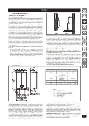
11. Boiler installation<br />
Decide upon the boiler location, then tape the template on the wall.<br />
Connect the pipework to the gas <strong>and</strong> water inlets prearranged on the template lower bar.<br />
If you are either installing the boiler on a pre-existent system or substituting it, we suggest you also<br />
fit settling tanks on the system return pipework <strong>and</strong> under the boiler to collect the deposits <strong>and</strong><br />
scaling which may remain <strong>and</strong> be circulated in the system after the purge.<br />
When the boiler is fixed on the template connect the flue <strong>and</strong> air ducts (fittings supplied by the<br />
manufacturer) according to the instructions given in the following sections.<br />
Connect the condensate outlet to the siphon supplied with the boiler. Connect the siphon to a drain,<br />
making sure there is a continuous slope. Horizontal sections must be avoided.<br />
BOILER WIDTH 450<br />
0207_2904<br />
BOILER CONNECTION<br />
POINTS<br />
9912220300<br />
BOILER HEIGHT 780<br />
MR: G3/4 heating flow<br />
US: G1/2 domestic hot water outlet<br />
GAS: G3/4 gas inlet to the boiler<br />
ES: G1/2 cold water inlet<br />
RR: G3/4 heating return<br />
SC: condensation drain<br />
Figure 6<br />
12. Boiler size<br />
020503_0300<br />
Figure 7<br />
13
13. Fittings present in the<br />
packaging<br />
• template<br />
• gas cock (16)<br />
• inlet water tap with filter (17)<br />
• heating system delivery cock (19)<br />
• heating system return cock (18)<br />
• washers<br />
• telescopic tubes<br />
• screws <strong>and</strong> wall plugs<br />
LUNA HT 280 - HT 330<br />
020503_0200<br />
LUNA HT 1.120 - HT 1.240 - HT 1.280<br />
0010270500<br />
Figure 8a<br />
19 16 17 18<br />
Figure 8b<br />
19<br />
16<br />
17<br />
18<br />
14. Installation of flue<br />
<strong>and</strong> air ducts<br />
We guarantee ease <strong>and</strong> flexibility of installation for a gas-fired forced draft boiler thanks to the<br />
fittings <strong>and</strong> fixtures supplied (described below).<br />
The boiler is especially designed for connection to an exhaust flue / air ducting, with either coaxial,<br />
vertical or horizontal terminal. By means of a splitting kit a two-pipe system may also be installed.<br />
In case exhaust <strong>and</strong> intake flues not supplied by BAXI S.p.A. have been installed, these must be<br />
certified for the type of use <strong>and</strong> must have a maximum pressure drop of 100 Pa.<br />
Warnings for the following types of installation:<br />
C 13<br />
, C 33<br />
The terminals for the split flue must be provided for within a square with 50 cm sides.<br />
Detailed instructions are given together with each accessory.<br />
C 53<br />
The terminals for combustion air intake <strong>and</strong> for the expulsion of combustion products must<br />
not be provided for on opposite walls of the building.<br />
C 63<br />
The maximum pressure drop of the ducts must not exceed 100 Pa. The ducts must be certified<br />
for the specific use <strong>and</strong> for a temperature of over 100°C. The chimney flue must be certified<br />
in accordance with the prEN 1856-1 Regulation.<br />
C 43<br />
, C 83<br />
The chimney or flue used must be suitable for the use.<br />
010828_0200<br />
C 33<br />
C 33<br />
C 13<br />
C 13<br />
C 43<br />
C 53<br />
C 83<br />
14<br />
Figure 9
Flue duct terminal<br />
Max. length<br />
of flue duct<br />
Each 90° bend<br />
reduces the duct<br />
max. length by<br />
Each 45° bend<br />
reduces the duct<br />
max. length by<br />
Flue<br />
terminal<br />
diameter<br />
Outer<br />
terminal<br />
diameter<br />
Coaxial Ø 60/100 mm<br />
Vertical two-pipe<br />
Horizontal two-pipe<br />
10 m<br />
15 m<br />
80 m<br />
1 m<br />
0,5 m<br />
0,5 m<br />
0,5 m<br />
0,25 m<br />
0,25 m<br />
100 mm<br />
133 mm<br />
-<br />
100 mm<br />
80 mm<br />
80 mm<br />
… coaxial flue - air duct (concentric)<br />
This type of duct allows to disengage exhaust gases<br />
<strong>and</strong> to draw combustion air both outside the<br />
building <strong>and</strong> in case a LAS flue is fitted.<br />
The 90° coaxial bend allows to connect the boiler<br />
to a flue-air duct in any direction as it can rotate by<br />
360°. It can moreover be used as a supplementary<br />
bend <strong>and</strong> be coupled with a coaxial duct or a 45°<br />
bend.<br />
990519_0400<br />
If the flue outlet is placed outside, the flue-air<br />
ducting must protrude at least 18mm out of the wall<br />
to allow alluminium weathering tile to be fitted <strong>and</strong><br />
sealed to avoid water leakages.<br />
Ensure a minimum downward slope of 1 cm<br />
towards the outside per each metre of duct length.<br />
Concentric outlet<br />
Figure 10<br />
A 90° bend reduces the total duct length by 1 metre.<br />
A 45° bend reduces the total duct length by 0.5 metre.<br />
Horizontal flue terminal Ø 60/100 mm installation options<br />
0002230400<br />
L max = 10 m<br />
L max = 10 m<br />
L max = 9 m<br />
L max = 9 m<br />
LAS flue duct Ø 60/100 mm installation options<br />
9912220900<br />
L max = 10 m<br />
15
Vertical flue terminal Ø 60/100 mm installation options<br />
This type of installation can be carried out both on a flat or pitched roof by fitting a terminal, an<br />
appropriate weathering tile <strong>and</strong> sleeve, (supplementary fittings supplied on dem<strong>and</strong>).<br />
9912221000<br />
L max = 10 m L max = 10 m L max = 8 m<br />
L max = 9 m<br />
… separated flue-air ducting<br />
This type of ducting allows to disengage exhaust flue gases both outside the building <strong>and</strong> into single<br />
flue ducts.<br />
Comburant air may be drawn in at a different site from where the flue terminal is located.<br />
The splitting kit consists of a flue duct adaptor (100/80) <strong>and</strong> of an air duct adaptor.<br />
For the air duct adaptor fit the screws <strong>and</strong> seals previously removed from the cap.<br />
flue duct adaptor<br />
011015_0100<br />
Intake air duct adaptor<br />
The 90° bend allows to connect the boiler to flue-air ducting regardless of direction as it can be<br />
rotated by 360°. It can moreover be used as a supplementary bend to be coupled with the duct or with<br />
a 45° bend.<br />
16
020503_0100<br />
A 90° bend reduces the total duct length by 0.5 metre.<br />
A 45° bend reduces the total duct length by 0.25 metre.<br />
Separated horizontal flue terminals installation options<br />
IMPORTANT: Ensure a minimum downward slope of 1 cm toward the outside per each metre of<br />
duct length<br />
Make sure that the exhaust <strong>and</strong> intake ducts are securely fixed to the walls.<br />
010828_0500<br />
(L1 + L2) max = 80 m<br />
010828_06≤00<br />
The maximum length of the suction<br />
duct must be 15 metres.<br />
L max = 15 m<br />
17
Separated vertical flue terminals installation options<br />
010828_0700<br />
L max = 15 m<br />
L max = 14 m<br />
Important: if fitting a single exhaust flue duct, ensure it is adequately insulated (e.g.: with glass wool)<br />
wherever the duct passes through building walls.<br />
For detailed instructions concerning the installation of fittings refer to the technical data accompanying<br />
the fittings.<br />
15. Connecting the mains<br />
supply<br />
Electrical safety of the appliance is only guaranteed by correct grounding, in compliance with the<br />
applicable laws <strong>and</strong> regulations.<br />
Connect the boiler to a 220-230V monophase + ground power supply by means of the three-pin cable<br />
supplied with it <strong>and</strong> make sure you connect polarities correctly.<br />
Use a double-pole switch with a contact separation of at least 3mm in both poles.<br />
In case you replace the power supply cable fit a HAR H05 VV-F’ 3x0.75mm 2 cable with an 8mm<br />
diameter max.<br />
The fuse, a fast-acting type rated 2A, is incorporated into the power supply terminals (remove the<br />
black fuse holder to enable inspection <strong>and</strong>/or replacement).<br />
Terminals M1<br />
020523_0400<br />
Terminals M2<br />
Cover<br />
Cover<br />
Figure 11<br />
18
15.1 Description of the electrical connections to the boiler<br />
Turn the control box downward to access terminal boards M1 <strong>and</strong> M2 used for the electrical connections<br />
by removing the two protective covers (see figure 11).<br />
Terminals 1-2: connection of SIEMENS model QAA73 temperature regulator supplied as accessory.<br />
Connection polarity is irrelevant.<br />
The jumper fitted across the “TA” terminals 3-4 must be removed.<br />
Read the instructions supplied with this accessory for correct installation <strong>and</strong> programming procedures.<br />
Terminals 3-4: “TA”, room temperature thermostat connection. Thermostats with integral accelerator<br />
resistor must not be used. Check that there is no voltage across the ends of the two thermostat<br />
connection wires.<br />
Terminals 5-6: “TP” floor temperature thermostat connection (commercially available device). Check<br />
that there is no voltage across the ends of the two thermostat connection wires.<br />
Terminals 7-8: connection of SIEMENS model QAC34 outdoor temperature probe supplied as<br />
accessory..<br />
Read the instructions supplied with this accessory for correct installation procedures.<br />
Terminals 9-10: connection of domestic hot water precedence temperature sensor supplied as accessory<br />
for connecting heating-only <strong>boilers</strong> to an external water heater.<br />
Terminals a-b (230V): electricity supply for a zone valve / pump<br />
See instructions in the “connecting a zone system” section.<br />
15.2 Connecting the QAA73 temperature regulator.<br />
The SIEMENS model QAA73 temperature regulator (optional accessory) must be connected to<br />
terminals 1-2 of terminal board M2 in figure 11.<br />
The jumper across terminals 3-4, provided for connection of a room temperature thermostat, must be<br />
removed.<br />
The settings of the domestic hot water temperature <strong>and</strong> domestic hot water production schedule must<br />
be made using this device.<br />
The timed program of the central heating circuit must be set on the QAA73 if there is a single zone,<br />
or in relation to the zone controlled by the QAA73 device.<br />
The timed program for the central heating circuit of the other zones can be set directly on the boiler<br />
control panel.<br />
See the instructions provided with the QAA73 temperature regulator for the user parameter<br />
programming procedure.<br />
IMPORTANT: For systems divided into zones, parameter 80 “HC2 gradient”, which can be set on<br />
the QAA73 temperature regulator, must be set as _ _ . _ “not active”.<br />
QAA73: parameters the installer can set (service)<br />
By pressing the two PROG buttons together for at least three seconds it is possible to access the list<br />
of parameters that the installer can display <strong>and</strong>/or set.<br />
Press either of these buttons to change the parameter to display or change.<br />
Press the [+] or [-] key to change the value displayed.<br />
Press either of the PROG buttons again to save the change.<br />
Press the information button (i) to quit programming.<br />
Here follows a list of the most commonly used parameters:<br />
19
Line no.<br />
Parameter<br />
Range<br />
Default value<br />
70<br />
HC1 gradient<br />
Selection of central heating circuit temperature curve “kt”<br />
2.5…40<br />
15<br />
72<br />
HC1 max. output<br />
Central heating system maximum output temperature<br />
25…85<br />
85<br />
74<br />
Type of building<br />
Light, Heavy<br />
Light<br />
75<br />
Room compensation<br />
Activation/deactivation of the influence of the room<br />
temperature. If it is deactivated, the outdoor temperature<br />
sensor must be installed.<br />
on HC1<br />
on HC2<br />
on HC1+HC2<br />
nil<br />
On HC1<br />
77<br />
Automatic adaptation of the temperature curve “kt” in<br />
relation to the room temperature.<br />
On - off<br />
On<br />
78<br />
Opt Start Max<br />
Maximum time the boiler is switched on ahead of the timed<br />
program to optimise the temperature in the premises.<br />
0…360 min<br />
0<br />
79<br />
Opt Stop Max<br />
Maximum time the boiler is switched off ahead of the timed<br />
program to optimise the temperature in the premises.<br />
0…360 min<br />
0<br />
80<br />
HC2 gradient<br />
Selection of temperature curve “kt” of the HC2 central<br />
heating circuit of the low temperature zone if the SIEMENS<br />
AGU2.500 accessory is used.<br />
2.5…40<br />
—.- = not active<br />
—.-<br />
82<br />
HC2 max. outputMax<br />
output temperature of the low temperature central heating<br />
system HC2<br />
25…85<br />
70<br />
90<br />
DHW Red Setp<br />
Minimum temperature of the domestic domestic hot water<br />
10 or 35…58<br />
10 or 35<br />
91<br />
DHW program<br />
Selection of the type of timed program for domestic hot<br />
water.<br />
24 h/day = always on<br />
PROG HC-1h = as HC1 central heating program less<br />
one hour<br />
PROG HC<br />
PROG ACS<br />
= as central heating program<br />
= specific domestic hot water program<br />
(see also program <strong>line</strong>s 30-36)<br />
24 h/day<br />
TSP HC-1h<br />
TSP HC<br />
TSP DHW<br />
24 h/day<br />
- fault messages<br />
In the event of fault, the display panel on the QAA73 shows the flashing symbol . Press the<br />
information key ( ) to display the error code <strong>and</strong> a description of the fault.<br />
Code Display Fault description<br />
10 Outside Sens External probe sensor fault or parameter 75 has been deactivated<br />
20 Boiler Sensor NTC delivery sensor fault<br />
50 DHW Sensor DHW NTC sensor fault<br />
60 Room Sensor QAA73 fault<br />
110 STL boiler Safety or flue thermostat tripping<br />
132 Safty Shutwn Floor thermostat tripping<br />
133 No flame Gas is low<br />
135 - No electricity supply to the fan<br />
151 BMU Error in boiler board. Shut off electric power to boiler for 10 seconds<br />
153 Interlock The RESET button has been pressed for no reason<br />
160 Fan speed Fan speed threshold not reached<br />
164 HE Flow/Press No permissive water differential pressure switch<br />
20
15.3 Connecting the outdoor temperature sensor probe<br />
The SIEMENS model QAC34 outdoor temperature sensor probe (optional accessory) must be<br />
connected to terminals 7-8 of terminal board M2 in figure 11.<br />
The procedures for setting the gradient of the temperature curve “kt” vary depending on the accessories<br />
connected to the boiler.<br />
a) Without accessories:<br />
The temperature curve “kt” must be selected by setting parameter H532 as described in section 17<br />
“setting the boiler parameters”.<br />
See graph 1 for selecting the curve referred to a room temperature of 20°C.<br />
The chosen curve can be shifted by pressing the (2), button (2) on the boiler control panel, <strong>and</strong><br />
modifying the value displayed by pressing the <strong>and</strong> . keys. See graph 2 for curve selection.<br />
(The example show in graph 2 refers to the curve Kt=15.<br />
Increase the value displayed if the room temperature required is not reached inside the premises for<br />
central heating.<br />
020523_0600<br />
TM = Flow temperature<br />
Te = Composite outside temperature<br />
Graph 1 Sth = Kt Curve<br />
Graph 2<br />
b) with QAA73 temperature regulator:<br />
The temperature curve “kt” must be selected by setting parameter 70 “HC1 gradient” of the QAA73<br />
temperature control device as described in section 15.2 “QAA73: parameters which can be set by the<br />
installation (service) engineer”.<br />
See graph 3 for selecting the curve referred to a room temperature of 20°C.<br />
The curve is shifted automatically on the basis of the room temperature set using the QAA73 climate<br />
control.<br />
If the system is divided into zones, the temperature curve “kt” relating to the part of the system not<br />
controlled by the QAA73 must be selected by setting parameter H532 as described in section 17<br />
“setting the boiler parameters”.<br />
IMPORTANT: For systems divided into zones, parameter 80 “HC2 gradient”, which can be set on<br />
the QAA73 temperature regulator, must be set as _ _ . _ “not active” (see section 15.2).<br />
020523_1000<br />
Graph 3<br />
TM = Flow temperature<br />
Te = Composite outside temperature<br />
21
c) with AGU2.500 for control of a low temperature system:<br />
Refer to the instructions provided with the AGU2.500 accessories for connection <strong>and</strong> control of a<br />
low temperature zone.<br />
15.4 Connecting a zoned system<br />
The electrical connection <strong>and</strong> settings needed to control a system divided into zones vary depending<br />
on the accessories connected to the boiler.<br />
a) Without accessories:<br />
The contact relating to the request for operation of the various zones must be parallel-connected <strong>and</strong><br />
connected to terminal 3-4 “TA” of terminal board M2 in figure 11. The jumper present must be<br />
removed.<br />
The central heating temperature is selected directly on the boiler control panel in accordance with the<br />
instructions provided for the user in this manual.<br />
b) with QAA73 temperature control device:<br />
The zone valve or pump relating to the room controlled by the QAA73 temperature control device<br />
must be supplied with electricity by means of terminals a-b of terminal board M1 in figure 11.<br />
The contact relating to the request for operation of the other zones must be parallel-connected <strong>and</strong><br />
connected to terminal 3-4 “TA” of terminal board M2 in figure 11. The jumper present must be<br />
removed.<br />
The central heating temperature of the zone controlled by the QAA73 is set automatically by the<br />
QAA73 itself.<br />
The central heating temperature of the other zones must be selected directly on the boiler control<br />
panel.<br />
IMPORTANT: For systems divided into zones, parameter 80 “HC2 gradient”, which can be set on<br />
the QAA73 temperature regulator, must be set as _ _ . _ “not active”.<br />
1 zone<br />
2 zone<br />
(room<br />
thermostat)<br />
3 zone<br />
(room<br />
thermostat)<br />
N zone<br />
(room<br />
thermostat)<br />
solenoid<br />
valve1 zone<br />
020523_0900<br />
Figure 12<br />
c) with AGU2.500 for control of a low temperature system:<br />
Refer to the instructions provided with the AGU2.500 accessories for connection <strong>and</strong> control of a<br />
low temperature zone.<br />
22
15.5 Connecting a remote water heater (for LUNA HT 1.120 - 1.240 - 1.280 models)<br />
LUNA HT 1.120 - 1.240 - 1.280 models are designed for connection of a remote water heater since<br />
they are fitted in the factory with a motor-operated three-way valve.<br />
Make the water connections to the water heater as shown in figure 13.<br />
Connect the NTC domestic hot water priority probe supplied as an accessory to terminals 9-10 of<br />
terminal board M2 in figure 11, first removing the electrical heating element fitted.<br />
The sensor element of the NTC probe must be fitted into the well provided on the water heater.<br />
The domestic hot water temperature can be set <strong>and</strong> the timed domestic hot water program selected<br />
directly on the boiler control panel as described in the instructions provided for the user in this<br />
manual.<br />
KEY<br />
UB: domestic hot water heater unit<br />
UR: central heating unit<br />
V3V: three-way valve<br />
M2: connection terminal board<br />
SB: domestic hot water heater priority sensor<br />
MR: central heating delivery<br />
MB: domestic hot water heater delivery<br />
RR: central heating/boiler return<br />
0207_0904<br />
Figure 13<br />
23
16. Gas change modalities<br />
A Qualified Service Engineer may adapt this boiler to operate with natural gas (G20) or with liquid<br />
gas (G31).<br />
Carry out the following operations in the given sequence:<br />
1) Calibration of the maximum heat output. Check that the CO 2<br />
measured on the flue, with the boiler<br />
operating at the maximum heat output, is the same as that shown in table 1. Otherwise, turn the<br />
regulation screw (V) on the gas valve. Turn the screw clockwise to increase the concentration of<br />
CO 2<br />
<strong>and</strong> anticlockwise to reduce it.<br />
2) Calibration of reduced heat output. Check that the CO 2<br />
measured on the flue, with the boiler<br />
operating at the minimum heat output, is the same as that shown in table 1. Otherwise, turn the<br />
offset regulation screw (K) on the gas valve. Turn the screw clockwise to increase the concentration<br />
of CO 2<br />
<strong>and</strong> anticlockwise to reduce it.<br />
Pi: Gas supply pressure connection point<br />
PO: Gas pressure to burner connection point<br />
P: Pressure connection point for<br />
measurement of the OFFSET<br />
Pl: Air signal input from fan<br />
V: Gas flow adjuster screw<br />
K: OFFSET adjuster screw<br />
020523_0700<br />
Figure 14<br />
To simplify calibration of the gas valve, the “calibration function” can be set directly on the boiler<br />
control panel by proceeding as follows:<br />
1) Press the keys (2-3) together until the display shows the pointer “ ” alongside the<br />
symbol (about 6 seconds).<br />
2) Press the keys to set the fan speed at the minimum <strong>and</strong> maximum heat output (%PWM);<br />
N.b - to set the minimum <strong>and</strong> maximum heat output quickly, press the<br />
keys respectively;<br />
3) press either of the two keys to exit the function.<br />
020429_0400<br />
Figure 15<br />
24
LUNA HT 330 G20 - 2H - 20 mbar G31 - 3P - 37 mbar<br />
LUNA HT 1.280<br />
CO 2<br />
max. heat output 8,7% ± 0,2 10% ± 0,2<br />
CO 2<br />
min. heat output 8,4% ± 0,2 9,8% ± 0,2<br />
Gas nozzle 12,0 mm 12,0 mm<br />
Table 1a<br />
LUNA HT 1.240 G20 - 2H - 20 mbar G31 - 3P - 37 mbar<br />
LUNA HT 280<br />
CO 2<br />
max. heat output 8,7% ± 0,2 10% ± 0,2<br />
CO 2<br />
min. heat output 8,4% ± 0,2 9,5% ± 0,2<br />
Gas nozzle 7,5 mm 7,5 mm<br />
Table 1b<br />
LUNA HT 1.120 G20 - 2H - 20 mbar G31 - 3P - 37 mbar<br />
CO 2<br />
max. heat output 8,7% ± 0,2 10% ± 0,2<br />
CO 2<br />
min. heat output 8,4% ± 0,2 9,5% ± 0,2<br />
Gas nozzle 4,0 mm 4,0 mm<br />
Table 1c<br />
LUNA HT 330<br />
Gas consumption at 15 °C G20 - 2H - 20 mbar G31 - 3P - 37 mbar<br />
1013 mbar<br />
PCI 34.02 MJ/m 3 46.3 MJ/kg<br />
Consumption at max. heat output 3.59 m 3 /h 2.64 kg/h<br />
Consumption at min. heat output 1.06 m 3 /h 0.78 kg/h<br />
Table 2a<br />
LUNA HT 280<br />
Gas consumption at 15 °C G20 - 2H - 20 mbar G31 - 3P - 37 mbar<br />
1013 mbar<br />
PCI 34.02 MJ/m 3 46.3 MJ/kg<br />
Consumption at max. heat output 3.06 m 3 /h 2.25 kg/h<br />
Consumption at min. heat output 0,95 m 3 /h 0.70 kg/h<br />
Table 2b<br />
LUNA HT 1.280<br />
Gas consumption at 15 °C G20 - 2H - 20 mbar G31 - 3P - 37 mbar<br />
1013 mbar<br />
PCI 34.02 MJ/m 3 46.3 MJ/kg<br />
Consumption at max. heat output 3.06 m 3 /h 2.25 kg/h<br />
Consumption at min. heat output 1,06 m 3 /h 0.78 kg/h<br />
Table 2c<br />
LUNA HT 1.240<br />
Gas consumption at 15 °C G20 - 2H - 20 mbar G31 - 3P - 37 mbar<br />
1013 mbar<br />
PCI 34.02 MJ/m 3 46.3 MJ/kg<br />
Consumption at max. heat output 2.61 m 3 /h 1.92 kg/h<br />
Consumption at min. heat output 0.74 m 3 /h 0.54 kg/h<br />
Table 2d<br />
LUNA HT 1.120<br />
Gas consumption at 15 °C G20 - 2H - 20 mbar G31 - 3P - 37 mbar<br />
1013 mbar<br />
PCI 34.02 MJ/m 3 46.3 MJ/kg<br />
Consumption at max. heat output 1.31 m 3 /h 0.96 kg/h<br />
Consumption at min. heat output 0,42 m 3 /h 0,31 kg/h<br />
Table 2e<br />
25
17. Setting the boiler<br />
parameters<br />
The boiler parameters may only be modified by professionally qualified staff proceeding as follows:<br />
a) press the , keys on the boiler’s front panel together for about 3 s until the parameter H90<br />
appears on the display;<br />
b) press the keys to select the parameter for modification;<br />
c) press the <strong>and</strong> keys to modify the parameter;<br />
d) press the key to exit the programming function.<br />
e) when programming is finished, warning message E183 will blink for 3 seconds approx.<br />
If the warning continues to blink or if other warnings are displayed, press the reset button<br />
When warning message E153 appears, press the reset button a second time.<br />
The following are the parameters generally used:<br />
Parameter N.<br />
H505<br />
H507<br />
H516<br />
H532<br />
H533<br />
H536<br />
H544<br />
H545<br />
H552<br />
H584<br />
H602<br />
H603<br />
H615<br />
Description<br />
Maximum temperature (°C) of the central heating circuit HC1 corresponding to:<br />
- the main circuit in systems with just one zone;<br />
- the circuit of the zone where the QAA73 temperature control device is installed<br />
in case of systems with more than one high-temperature zone;<br />
- the high temperature zone circuit in mixed systems <strong>and</strong> if the SIEMENS<br />
AGU2.500 accessory is used.<br />
Maximum temperature (°C) of the central heating circuit HC2 of a system with<br />
more than one zone, corresponding to the circuit of the low-temperature zone if<br />
the SIEMENS AGU2.500 accessory is used.<br />
Automatic Summer / Winter switching temperature (°C).<br />
Selection of temperature curve of central heating circuit HC1 (see Graph 1)<br />
Selection of temperature curve of central heating circuit HC2 (see Graph 1)<br />
Selection of central heating power (N. of fan rpm)<br />
Pump post-circulation time in central heating mode (min)<br />
Burner operating pause time between two start-ups (s)<br />
Hydraulic system setting (see instructions provided with the SIEMENS<br />
AGU2.500 accessory)<br />
Pump / three-way valve anti-blocking operating time (s)<br />
Heat exchanger preheating holding time after operation in domestic hot water<br />
mode (min)<br />
Heat exchanger preheating holding time after operation in central heating mode<br />
(min)<br />
Programmable function:<br />
- “0” electricity supply to zone pump / valve <strong>and</strong> use of the SIEMENS<br />
AGU2.500 accessory;<br />
- “1” electricity supply to a remote LPG gas valve;<br />
- “5” electricity supply to zone pump / valve in the absence of the SIEMENS<br />
AGU2.500 accessory.<br />
Only one of these functions can be selected.<br />
Factory setting<br />
80<br />
70<br />
20<br />
15<br />
15<br />
See table 3<br />
3<br />
180<br />
See table 3<br />
10<br />
0<br />
0<br />
5<br />
Parameter N LUNA HT 280 LUNA HT 330 LUNA HT 1.120 LUNA HT 1.240 LUNA HT 1.280<br />
H536 4900 4550 5650 5900 4550<br />
H552 38 38 35 35 35<br />
Table 3<br />
If the electronic circuit board is replaced, make sure that the parameters set are those specific to the<br />
boiler model, as indicated in the documentation available from the authorised Service Centre.<br />
26
18. Control <strong>and</strong> operation<br />
devices<br />
The boiler has been designed in full compliance with European reference st<strong>and</strong>ards <strong>and</strong> in particular<br />
is equipped with the following<br />
• Overheat thermostat<br />
Thanks to a sensor placed on the heating flow, this thermostat interrupts the gas flow to the main<br />
burner in case the water contained in the primary system has overheated. Under these conditions<br />
the boiler locks out <strong>and</strong> you can only repeat the ignition procedure by pressing the reset button on<br />
the boiler after you have remedied the cause of the trip.<br />
It is forbidden to disenable this safety device<br />
• Flue thermostat<br />
This device, positioned on the flue inside the boiler, interrupts the flow of gas to the burner if the<br />
temperature exceeds 90 °C. After verifying the cause of the trip, press the reset button positioned<br />
on the thermostat itself, then press the release button on the boiler.<br />
It is forbidden to disenable this safety device<br />
• Flame ionization detector<br />
The flame sensing electrode guarantees safety of operation in case of gas failure or incomplete<br />
interlighting of the main burner.<br />
Under such conditions the boiler is blocked.<br />
You must press the reset button on the boiler to restore the normal operating conditions.<br />
• Hydraulic differential pressure sensor<br />
This pressure sensor, fitted on the hydraulic assembly, allows the main burner to light provided the<br />
pump head is as required <strong>and</strong> protects the flue-water exchanger from possible lacks of water or<br />
blockings of the pump.<br />
• Supplementary running of the pump<br />
The electronically-controlled supplementary running of the pump lasts 3 minutes, when the boiler<br />
is in the central heating mode, after the burner has switched off due to a room thermostat intervention.<br />
• Frost protection device<br />
Boilers electronic management includes a “frost protection” function in the central heating system<br />
which operates the burner to reach a heating flow temperature of 30°C when the system heating<br />
flow temperature drops below 5 °C.<br />
This function is enabled as long as the boiler is connected to the a.c. power <strong>and</strong> gas supplies <strong>and</strong><br />
the pressure in the system is as specified.<br />
• Pump-blocking prevention<br />
In case there is no call for heat either from the central heating system or from the DHW system for<br />
24 hours on end the pump will automatically switch on for 10 seconds.<br />
• 3-way antiblocking valve<br />
If there is no heat dem<strong>and</strong> for a period of 24 hours the 3-way valve switches completely.<br />
This function is enabled if the electrical supply to the boiler is on.<br />
• Hydraulic safety valve (heating circuit)<br />
This device is set to 3 bar <strong>and</strong> is used for the heating circuit<br />
The safety valve should be connected to a siphoned drain. Use as a means of draining the heating<br />
circuit is strictly prohibited.<br />
27
19. Positioning of the ignition<br />
<strong>and</strong> flame sensing electrode<br />
010905_0200<br />
Figure 16<br />
20. Check of combustion<br />
parameters<br />
To measure combustion performance <strong>and</strong> hygiene levels of combustion products, the forced draught<br />
boiler models are equipped with two test points on the tapered coupling specifically designed for this<br />
purpose.<br />
One of the two test points is connected to the exhaust flue duct to allow measurements of the combustion<br />
products hygienic st<strong>and</strong>ards <strong>and</strong> combustion efficiency.<br />
The second test point is connected to the comburant air inlet duct to check possible combustion<br />
products circulation in case of coaxial ducts.<br />
The exhaust flue duct test point allows measurements of the following:<br />
• combustion products temperature;<br />
• concentration of oxygen (O 2<br />
) or, alternatively, of carbon dioxyde (CO 2<br />
);<br />
• concentration of carbon monoxyde (CO).<br />
The comburant air temperature must be measured at the test point connected to the air inlet duct.<br />
020429_0300<br />
flue gas<br />
combustion air<br />
gasket<br />
Figure 17<br />
21. Activating the flue-sweeper<br />
function<br />
To facilitate measurement of the combustion efficiency <strong>and</strong> improve the clean<strong>line</strong>ss of the production<br />
products, the flue-sweeper function can be activated by proceeding as described below:<br />
1) press the (2-3) together until the pointer “ ” appears on the display alongside the symbol<br />
(about 3 seconds but no more than 6 seconds). In these conditions, the boiler operates at the<br />
maximum heat output set for central heating.<br />
2) press either of the buttons to exit the function<br />
28
020429_0200<br />
Figure 18<br />
22. Output / pump head<br />
performances<br />
This is a high static head pump fit for installation on any type of single or double-pipe heating<br />
systems. The air vent valve incorporated in the pump allows quick venting of the heating system.<br />
PUMP HEAD mH 2<br />
O<br />
020523_1100<br />
Graph 4<br />
OUTPUT l/hh<br />
23. How to disassemble the<br />
DHW heat exchanger<br />
(LUNA HT 280 - HT 330)<br />
The stainless steel plate-type DHW heat exchanger is easily disassembled with a screwdriver by<br />
operating as described below:<br />
• drain, if possible, only the boiler system, through the drain tap;<br />
• drain the DHW system from water;<br />
• remove the circulation pump;<br />
• remove the two srews (right in front of you) securing the DHW heat exchanger <strong>and</strong> pull it off its<br />
seat (Figure 19).<br />
flow sensing<br />
securing nut<br />
020429_0100<br />
Figure 19<br />
DHW heat exchanger<br />
securing screws<br />
29
To purge the exchanger <strong>and</strong>/or the DHW system we suggest the use of Cillit FFW-AL or Beckinser<br />
HF-AL.<br />
For specific areas where water hardness exceeds 20°F (1°F = 10 mg of calcium carbonate per one<br />
litre of water) we recommend you install a polyphosphate metering device - complying with the<br />
applicable regulations - in the cold water inlet pipework.<br />
24. Cleaning the cold water<br />
filter<br />
(LUNA HT 280 - HT 330)<br />
25. Annual service<br />
The boiler is equipped with a cold water filter placed on the hydraulic assembly. To clean it do the<br />
following:<br />
• drain the DHW system from water.<br />
• unscrew the nut on the flow sensing assembly (Figure 19).<br />
• pull out the flow sensing device <strong>and</strong> its filter.<br />
• remove the impurities.<br />
Important: in the event of replacements <strong>and</strong>/or cleaning of the O-rings on the hydraulic unit, do not<br />
use oil or grease as lubricant but exclusively Molykote 111.<br />
To ensure the boiler operates at peak efficiency, the following checks must be performed every year:<br />
• check on the appearance <strong>and</strong> tightness of the gas <strong>and</strong> combustion circuit gaskets;<br />
• check on the condition <strong>and</strong> position of the ignition <strong>and</strong> flame sensing electrodes (see section 19);<br />
• check on the condition of the burner <strong>and</strong> its fixing to the aluminium flange;<br />
• check for any dirt in the combustion chamber. Use a vacuum-cleaner for this cleaning operation,<br />
• check that the gas valve is calibrated correctly (see section 16);<br />
• check if the siphon is dirty;<br />
• check on the central heating system pressure.<br />
• check on the expansion vessel pressure.<br />
30
26.1 Boiler schematic<br />
LUNA HT 280 - HT 330<br />
010903_0100<br />
heating domestic water gas domestic water heating<br />
inlet outlet inlet return<br />
Figure 20<br />
Legenda:<br />
1 heating delivery cock<br />
2 gas service cock<br />
4 boiler filling tap<br />
4 cold water inlet on/off valve <strong>and</strong> filter<br />
5 heating return cock<br />
6 DHW NTC sensor / water heater NTC sensor<br />
7 DHW priority sensor<br />
8 check valve<br />
9 flow sensor with filter <strong>and</strong> water flow rate limiter<br />
10 hydraulic differential pressure sensor microswitch<br />
11 manometer<br />
12 pressure relief valve<br />
13 boiler drain point<br />
14 pump <strong>and</strong> air separator<br />
15 automatic air vent<br />
16 plate-type DHW heat exchanger<br />
17 gas valve<br />
18 flue-water exchanger<br />
19 flame detector electrode<br />
20 main burner<br />
21 ignition electrode<br />
22 air/gas mixture header<br />
23 mixer with venturi<br />
24 gas diaphragm<br />
25 fan<br />
26 flue thermostat<br />
27 coaxial fitting<br />
28 automatic air vent<br />
29 expansion vessel<br />
30 fumes header<br />
31 siphon<br />
32 105°C overheat thermostat<br />
33 central heating NTC sensor<br />
34 3-way valve motor<br />
35 diverter valve assembly<br />
36 hydraulic differential pressure sensor<br />
37 automatic bypass<br />
31
26.2 Boiler schematic<br />
LUNA HT 1.120 - HT 1.240<br />
HT 1.280<br />
0206_1401<br />
heating storage gas domestic water heating<br />
inlet tank feed inlet return<br />
Figure 21<br />
Legenda:<br />
1 heating delivery cock<br />
2 gas service cock<br />
4 boiler filling tap<br />
5 heating return cock<br />
10 hydraulic differential pressure sensor microswitch<br />
11 manometer<br />
12 pressure relief valve<br />
13 boiler drain point<br />
14 pump <strong>and</strong> air separator<br />
15 automatic air vent<br />
17 gas valve<br />
18 flue-water exchanger<br />
19 flame detector electrode<br />
20 main burner<br />
21 ignition electrode<br />
22 air/gas mixture header<br />
23 mixer with venturi<br />
24 gas diaphragm<br />
25 fan<br />
26 flue thermostat<br />
27 coaxial fitting<br />
28 automatic air vent<br />
29 expansion vessel<br />
30 fumes header<br />
31 siphon<br />
32 105°C overheat thermostat<br />
33 central heating NTC sensor<br />
34 3-way valve motor<br />
35 diverter valve assembly<br />
36 hydraulic differential pressure sensor<br />
37 automatic bypass<br />
32
27.1 Illustrated wiring diagram<br />
LUNA HT 280 - HT 330<br />
0206_2605<br />
33
27.2 Illustrated wiring diagram<br />
LUNA HT 1.120 - HT 1.240 - HT 1.280<br />
0206_2604<br />
34
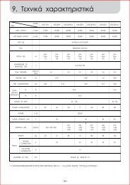
28. Technical data<br />
Boiler model LUNA HT 280 330 1.120 1.240 1.280<br />
Category II 2H3P<br />
II 2H3P<br />
II 2H3P<br />
II 2H3P<br />
II 2H3P<br />
DHW rated heat input kW 28,9 34 - - -<br />
CH rated heat input kW 24,7 28,9 12,4 24,7 28,9<br />
Reduced heat input kW 9 9,7 4 7 9,7<br />
DHW rated heat output kW 28 33 - - -<br />
kcal/h 24.080 28.380 - - -<br />
CH rated heat output 75/60°C kW 24 28 12 24 28<br />
kcal/h 20.640 24.080 10.320 20.640 24.080<br />
CH rated heat output 50/30°C kW 25,9 30,3 13 25,9 30,3<br />
kcal/h 22.270 26.060 11.180 22.270 26.060<br />
Rated heat output 75/60°C kW 8,7 9.4 3,9 6.8 9.4<br />
kcal/h 7.480 8.090 3.350 5.850 8.090<br />
Rated heat output 50/30°C kW 9,5 10.2 4,2 7.4 10.2<br />
kcal/h 8.170 8.770 3.610 6.360 8.770<br />
Central heating system max. pressure bar 3 3 3 3 3<br />
Expansion vessel capacity l 10 10 8 8 10<br />
Expansion vessel pressure bar 0,5 0,5 0,5 0,5 0,5<br />
DHW system max. pressure bar 8 8 - - -<br />
DHW system min. dynamic pressure bar 0,2 0,2 - - -<br />
DHW system min. output l/min 2,5 2,5 - - -<br />
DHW production at ∆T=25 °C l/min 16,1 18,9 - - -<br />
DHW production at ∆T=35 °C l/min 11,5 13,5 - - -<br />
Specific output (*)“D” l/min 12,9 15,3 - - -<br />
Concentric flue duct diameter mm 60 60 60 60 60<br />
Concentric air duct diameter mm 100 100 100 100 100<br />
2-pipe flue duct diameter mm 80 80 80 80 80<br />
2-pipe air duct diameter mm 80 80 80 80 80<br />
Max. flue mass flow rate kg/s 0,014 0,016 0,006 0,012 0,014<br />
Min. flue mass flow rate kg/s 0,004 0,005 0,002 0,003 0,005<br />
Max. flue temperature °C 75 75 73 73 75<br />
Type of gas used — G20 G20 G20 G20 G20<br />
— G31 G31 G31 G31 G31<br />
Natural gas feeding pressure mbar 20 20 20 20 20<br />
Propane gas feeding pressure mbar 37 37 37 37 37<br />
Power supply voltage V 230 230 230 230 230<br />
Power supply frequency Hz 50 50 50 50 50<br />
Rated power supply W 155 160 145 150 155<br />
Net weight kg 45,5 46,5 44 45 46<br />
Dimensions height mm 763 763 763 763 763<br />
width mm 450 450 450 450 450<br />
depth mm 354 354 354 354 354<br />
Protection-limit against humidity <strong>and</strong> water leakages (**) IPX5D IPX5D IPX5D IPX5D IPX5D<br />
(*) according to EN 625<br />
(**) according to EN 60529<br />
35
BAXI S.p.A., in its commitment to constantly improve its products, reserves the right to alter the specifications contained herein at any time <strong>and</strong> without previous warning.<br />
These Instructions are only meant to provide consumers with use information <strong>and</strong> under no circumstance should they be construed as a contract with a third party.<br />
BAXI S.p.A.<br />
36061 BASSANO DEL GRAPPA (VI) ITALIA<br />
Via Trozzetti, 20<br />
Tel. 0424 - 517111<br />
Telefax 0424/38089<br />
C603677A