Efficient Compliance Checking Using BPMN-Q and Temporal Logic
Efficient Compliance Checking Using BPMN-Q and Temporal Logic
Efficient Compliance Checking Using BPMN-Q and Temporal Logic

You also want an ePaper? Increase the reach of your titles
YUMPU automatically turns print PDFs into web optimized ePapers that Google loves.
<strong>Efficient</strong> <strong>Compliance</strong> <strong>Checking</strong> <strong>Using</strong> <strong>BPMN</strong>-Q <strong>and</strong><br />
<strong>Temporal</strong> <strong>Logic</strong><br />
Ahmed Awad, Gero Decker, Mathias Weske<br />
Business Process Technology Group<br />
Hasso-Plattner-Institute, University of Potsdam, Germany<br />
{ahmed.awad,gero.decker,weske}@hpi.uni-potsdam.de<br />
Abstract. <strong>Compliance</strong> rules describe regulations, policies <strong>and</strong> quality constraints<br />
a business process must adhere to. Given the large number of rules<br />
<strong>and</strong> their frequency of change, manual compliance checking can become<br />
a time-consuming task. Automated compliance checking is an alternative<br />
whenever business processes <strong>and</strong> compliance rules are described in<br />
a formal way. This paper introduces an approach for automated compliance<br />
checking based on <strong>BPMN</strong>-Q queries. The queries are translated into<br />
PLTL formulae that serve as input to model checkers which in turn verify<br />
whether a process model satisfies the requested behavior. To address the<br />
problem of state-space explosion we employ a set of reduction rules. The<br />
approach is prototypically realized <strong>and</strong> evaluated.<br />
1 Introduction<br />
<strong>Compliance</strong> of business processes with regulations, policies <strong>and</strong> quality constraints<br />
is a challenging task. Such compliance rules originate from different<br />
sources <strong>and</strong> keep changing over time. Also, these rules address different aspects<br />
of business processes, for example a certain order of execution between<br />
activities is required. Other rules force the presence of activities, e.g. reporting<br />
financial transactions to an external entity. The obligation of adhering to rules<br />
ranges from gaining competitive advantage to employing strategies that protect<br />
businesses from failure, e.g. Basel II 1 in the field of risk assessment in the<br />
banking sector, other regulations come as quality st<strong>and</strong>ards like ISO 9000. On<br />
the other extreme, regulations might come with the enforceability of law like<br />
the Sarbanes-Oxley Act of 2002 [1]. Violation could lead to penalties, sc<strong>and</strong>als<br />
<strong>and</strong> loss of business reputation.<br />
The changing nature of rules (due to e.g. changes in policies) calls for checking<br />
business processes each time a rule is added or changed. As a result, organizations<br />
need to hire compliance experts auditing their process models. In<br />
the case of manual auditing, a considerable amount of time is consumed in<br />
identifying the set of process models affected by each rule before revising them<br />
for compliance; something that may lead to failure to meet the deadline for<br />
declaring compliance.<br />
1 See http://www.Basel-II.info
Obtain<br />
Customer<br />
Info<br />
Non-VIP<br />
Retrieve<br />
Full<br />
Customer<br />
Dtl<br />
VIP<br />
Analyze<br />
Customer<br />
Relation<br />
Propose<br />
Account<br />
Opening<br />
Receive<br />
customer<br />
request<br />
Identify<br />
Customer<br />
Info<br />
Select<br />
Deposit<br />
Service<br />
Submit<br />
Deposit<br />
Record<br />
Customer<br />
Info<br />
Prepare<br />
Prop. Doc<br />
Schedule<br />
Status<br />
Review<br />
Open Acc<br />
Status<br />
Review<br />
Verify<br />
Customer<br />
ID<br />
Open<br />
Account<br />
Record<br />
Acc<br />
Info<br />
Apply Acc<br />
Policy<br />
Activate<br />
Acc<br />
Do<br />
Deposit<br />
Validate<br />
Acc Info<br />
Close Acc<br />
Evaluate<br />
Deposit<br />
Val<br />
Report<br />
Large<br />
Deposit<br />
Notify<br />
Customer<br />
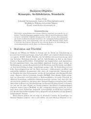
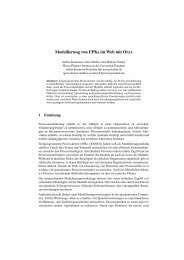
Fig. 1. Banking business process model adapted from [18]<br />
The contribution of this paper is twofold. First, it presents an automated approach<br />
for checking compliance of business process models regarding ordering<br />
constraints for activities. Automation is achieved by expressing rules as queries<br />
in a visual language we developed earlier [2]. These queries determine the set of<br />
process models that are c<strong>and</strong>idates for further compliance checking. This activity<br />
is already very time consuming in manual auditing. <strong>Efficient</strong>ly determining<br />
whether process models comply to the rules using model checking is the second<br />
contribution. Our approach is not limited to processes defined in <strong>BPMN</strong>, it can<br />
be applied to any graph based process definition language as described below.<br />
The remainder of this paper is structured as follows. In Section 2 we discuss<br />
a scenario in the banking business <strong>and</strong> derive a set of rules. Section 3 discusses<br />
how we adapted <strong>BPMN</strong>-Q to express compliance rules as queries. Details of<br />
applying model checking to formally verify compliance is given in Section 4.<br />
Related work is reported in Section 5, before we conclude the paper in Section 6.<br />
2 <strong>Compliance</strong> Example<br />
In this section, we introduce a business process from the banking sector. It will<br />
serve as example throughout the paper. In the financial sector, banks are obliged<br />
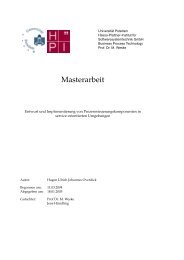
to conform to several compliance rules. Consider the process model in Figure 1<br />
(expressed in <strong>BPMN</strong> notation) for opening a bank account.<br />
The process starts with ”Receive customer request” to open an account. Customer<br />
information is obtained from the request <strong>and</strong> identified. In case of a<br />
non-VIP customer, her detailed information is retrieved <strong>and</strong> its relation to the<br />
bank is analyzed. If the customer selects to open a deposit account, an extra deposit<br />
form must be submitted <strong>and</strong> the customer’s information is recorded. With<br />
all previous steps completed, a proposal document is prepared by a bank’s employee<br />
for further analysis. A proposal’s status review is scheduled along with<br />
the proposal of opening an account. Later on, the customer’s identity is verified
<strong>and</strong> the status of the account is reviewed. An account is opened at that point<br />
followed by a validation of account information. If validation fails the account<br />
is closed. With valid account information, an account policy is applied before<br />
the account is activated. Finally the account information is recorded <strong>and</strong> the<br />
account is ready for transactions. Large deposit transactions (”Evaluate Deposit<br />
Val”) are reported to a central bank to track the possibility of money laundering.<br />
At the end of the process the customer is notified.<br />
The process has to comply with several rules. Among them are rules to<br />
prevent money laundering. The rules dem<strong>and</strong> that an account is not opened<br />
until certain checks have been completed. We selected the following two rules<br />
to guide the discussion in this paper.<br />
– Rule 1: Before opening an account, customer information must be obtained<br />
<strong>and</strong> verified. The rule delays the activity ”open account” until information<br />
about the customer has been verified e.g. checking absence from black lists<br />
containing undesirable customers. Violation of this rule may lead to opening<br />
an account for individuals that are known to be on the black list of e.g. the<br />
central bank.<br />
– Rule 2: Whenever a customer requests to open a deposit account, customer<br />
information must be recorded before opening the account. Information must<br />
be recorded to ease future tracking of their transactions <strong>and</strong> identifying them<br />
in case they run large deposit transactions.<br />
3 Declarative Representation of <strong>Compliance</strong> Rules<br />
As mentioned in Section 1, the first contribution of this paper is the automated<br />
discovery of process models that are relevant to a given rule (see Definition 3).<br />
To determine these relevant process models, we express rules concerned with<br />
ordering of activities as queries in <strong>BPMN</strong>-Q. Before we go further with the<br />
details of using <strong>BPMN</strong>-Q to express compliance rules, we briefly introduce<br />
<strong>BPMN</strong>-Q. Next, we discuss how to adapt it for compliance checking.<br />
<strong>BPMN</strong>-Q [2] is a visual language based on <strong>BPMN</strong>. It is used to query business<br />
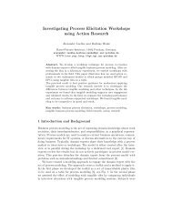
process models by matching a process graph to a query graph. Figure 2 sketches<br />
an overview of the steps of processing a query. In addition to the sequence flow<br />
Process Model<br />
Repository<br />
Relevant Process<br />
Models Filter<br />
Process Model P<br />
Query Processor Process Model P’<br />
<strong>BPMN</strong>-Q<br />
query<br />
Fig. 2. Overview of query processing in <strong>BPMN</strong>-Q<br />
edges in <strong>BPMN</strong>, <strong>BPMN</strong>-Q introduces the concept of path (see edge in Figure 3<br />
(b)). When matching a process graph (like the one in Figure 3 (a)) to the query
in (b), the result of the path edge is the sub-graph of the matching process in<br />
which the two nodes along with nodes in between (Figure 3 (c)).<br />
A B C D E<br />
(a) A process model<br />
B<br />
//<br />
D<br />
B C D<br />
(b) a query with path element connecting nodes B, D<br />
(c ) a sub-graph from process in (a) matching the query in (b)<br />
Fig. 3. Example of a <strong>BPMN</strong>-Q query<br />
We now define process graphs, where the set of nodes N can be either<br />
activities, events or gateways. Set F represents the sequence flow edges that<br />
can connect nodes. The definition is adapted from [4].<br />
Definition 1. A process graph is a tuple PG= (N, A, E, G , F ) where<br />
– N is a finite set of nodes that is partitioned into the set of activities A, the set of<br />
events E, <strong>and</strong> the set of gateways G<br />
– The set of events E can be further partitioned into:<br />
• Start events E s i.e. nodes with no incoming edges.<br />
• Intermediate events E i .<br />
• End events E e i.e. nodes with no outgoing edges.<br />
– F ⊆ (N \ E e ) × (N \ E s ) is the sequence flow relation between nodes.<br />
<strong>BPMN</strong>-Q provides more types of edges to connect nodes. It is possible to express<br />
in the query what we call negative edges NS, <strong>and</strong> negative paths NP. They<br />
represent further constraints on the process graph to match the query. For instance<br />
if nodes A <strong>and</strong> B are connected with a negative edge in the query graph,<br />
it means that in any match to the query the nodes A <strong>and</strong> B must not have a<br />
sequence flow edge between them. The same applies to negative paths.<br />
Definition 2. A query graph is a tuple QG= (NQ, AQ, EQ,GQ, S,NS, PA, NP)<br />
where<br />
– NQ is a finite set of nodes that is partitioned into the set of activities AQ, the set<br />
of events EQ, <strong>and</strong> the set of gateways GQ<br />
– S ⊆ NQ × NQ is the set of sequence flow edges between nodes.<br />
– NS ⊆ NQ × NQ is the set of negative sequence flow edges between nodes.<br />
– PA ⊆ NQ × NQ is the set of path edges between nodes.<br />
– NP ⊆ NQ × NQ is the set of negative path edges between nodes.<br />
A process graph is relevant to a query graph only if the set of activity nodes<br />
in a process graph is a superset of the activity nodes in a query graph.<br />
Definition 3. A process graph p is relevant to query graph q iff A ⊇ AQ
To address the execution ordering between activities , a process graph is divided<br />
into a set of execution paths. An execution path is a sequence of nodes starting<br />
from one of the process start node(s) <strong>and</strong> ending at one of its end node(s).<br />
Definition 4. An execution path exp is a sequence of nodes (n 0 , . . . , n k ) where n 0 , . . . , n k ∈<br />
N, n 0 ∈ E s <strong>and</strong> n k ∈ E e . EXP is the set of all execution paths in a given process graph.<br />
We can determine the execution order between two nodes a, b in a process<br />
graph with respect to an execution path exp by finding the precedence between<br />
the first occurrence of node a <strong>and</strong> occurrence of node b. 2<br />
Definition 5. An execution ordering relation between nodes on an execution path exp<br />
is defined as < exp = {(n ′ , n ′′ ) ∈ N : n ′ ∈ 3 exp ∧ n ′′ ∈ exp ∧ ∃i, j(n ′ = n i ∧ n ′′ = n j ∧ i<br />
If <strong>BPMN</strong>-Q does not find a match i.e. it fails to find an execution path from<br />
Record Customer Info to Open Account then we are sure that the answer to rule<br />
2 is “NO”. On the other h<strong>and</strong> if the matching succeeds <strong>and</strong> a path is found,<br />
we cannot be sure that this execution path is activated in all possible execution<br />
scenarios. That is because the path element does not consider the semantics of<br />
control nodes in execution paths. We record this as a limitation that we will<br />
resolve in this paper.<br />
Another limitation is the ability to express the direction of the execution<br />
dependency between activities. For instance, determining the order of execution<br />
between two activities A <strong>and</strong> B in Figure 5 by finding path from A to B, are we<br />
interested in being sure that every execution of activity A will lead to execution<br />
of Activity B, or on the other h<strong>and</strong> each time activity B is executed it must have<br />
been preceded by an execution of activity A. The two situations are different. In<br />
the first one we state a constraint over the future states of a process execution<br />
while in the second one we state this constraint over its past execution states.<br />
From this simple process fragment, we can see that activity B is preceded by<br />
B<br />
A<br />
D<br />
C<br />
Fig. 5. A fragment of a process model to show difference between leads to <strong>and</strong> precedes<br />
concepts<br />
activity A but activity A does not lead to activity B. The two concepts of precedes<br />
<strong>and</strong> leads to are not distinguishable in queries. To overcome these limitations we<br />
decided to:<br />
– Extend <strong>BPMN</strong>-Q with precedes <strong>and</strong> leads to qualifiers to solve the second<br />
limitation.<br />
– Use Model checking as a formal approach to verify constraints against<br />
process sub-graphs to solve the first limitation.<br />
To visually differentiate between the precedes <strong>and</strong> leads to semantics we simply<br />
added them under the arc representing the path operator like ≪precedes≫ <strong>and</strong><br />
≪leads to≫ respectively in a way similar to the stereotypical extension in UML.<br />
Now queries from Figure 4 will look as in Figure 6. The formalism behind these<br />
two concepts is given within the context of this section along with necessary<br />
supporting definitions.<br />
To say that node A in a process graph leads to (see Definition 8) node B,<br />
we just need to be sure that every execution path going through A also goes<br />
through B. On the other h<strong>and</strong> node A precedes (Definition 9) node B only if all<br />
execution paths gone through B have gone through node A before.<br />
Definition 8. Node m leads to node n iff ∀exp ∈ EXP(m ∈ exp ⇒ n ∈ exp ∧ m < exp n)
Obtain<br />
Customer Info<br />
//<br />
<br />
Verify<br />
Customer ID<br />
//<br />
<br />
Open<br />
Account<br />
Submit<br />
Deposit<br />
Record<br />
// //<br />
Customer Info <br />
Open<br />
Account<br />
Rule 1<br />
Fig. 6. Queries refined<br />
Rule 2<br />
Definition 9. Node m precedes node n iff ∀exp ∈ EXP(n ∈ exp ⇒ m ∈ exp ∧ m < exp n)<br />
We can read queries as follows:<br />
– Rule 1: The execution of ”Obtain Customer Info” <strong>and</strong> ”verify customer ID”<br />
always leads to execution of ”Open Account” i.e. leads to (Obtain Customer<br />
Info, Open Account) <strong>and</strong> leads to (Verify Customer ID, Open Account).<br />
– Rule 2: The execution of submit deposit leads to recording customer info,<br />
which must precede opening an account i.e. leads to (Submit Deposit, Record<br />
Customer Info) <strong>and</strong> precedes (Record Customer Info, Open Account).<br />
The effects of these extensions are more than just a visual differentiation<br />
between the leads to <strong>and</strong> precedes concepts. One further effect is the temporal<br />
expression generated from each rule, shown in the next section. Another effect<br />
is on the query itself. In case of precedes paths we add a start event to the query<br />
graph (in case the query does not already have one) <strong>and</strong> a path operator between<br />
the start event <strong>and</strong> the destination of the precedes operator. This path is added<br />
to allow the query to match all possible paths from the beginning of the process<br />
to the destination activity of the precedes operator in order to give the model<br />
checker the possibility to find violations (if any).<br />
4 <strong>Efficient</strong> Analysis using <strong>Temporal</strong> <strong>Logic</strong><br />
This section discusses how compliance checking on <strong>BPMN</strong> process models can<br />
be carried out. The compliance rules are formulated as <strong>BPMN</strong>-Q queries. Our<br />
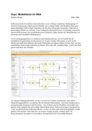
approach can be divided into the following steps, which are also illustrated in<br />
Figure 7.<br />
1. Retrieval of <strong>BPMN</strong> sub-graphs. A query processor takes a <strong>BPMN</strong>-Q query<br />
as input <strong>and</strong> retrieves a number of <strong>BPMN</strong> sub-graphs from a <strong>BPMN</strong> process<br />
model repository. Only those process models are considered that structurally<br />
match the <strong>BPMN</strong>-Q query.<br />
2. Graph reduction. The sub-graphs are reduced, mainly removing activities<br />
<strong>and</strong> gateways that are not relevant to the query.<br />
3. Petri net generation. The reduced sub-graphs are translated into Petri nets.<br />
4. State space generation. The Petri nets are checked for boundedness <strong>and</strong> the<br />
reachability graph is calculated.<br />
5. Generation of temporal logic formulae. The <strong>BPMN</strong>-Q query is translated<br />
into temporal logic formulae.
6. Model checking. The finite state machines <strong>and</strong> the temporal logic formulae<br />
are fed into a model checker. The model checker verifies whether the temporal<br />
logic formulae are respected by the given state machines. As a result,<br />
it is detected which process models comply to the initial <strong>BPMN</strong>-Q queries.<br />
<strong>BPMN</strong>-Q<br />
query<br />
<strong>BPMN</strong> process<br />
model<br />
LTL formulae<br />
generator<br />
Query<br />
processor<br />
<strong>BPMN</strong><br />
sub-graph<br />
Graph<br />
reducer<br />
Reduced<br />
sub-graph<br />
Petri net<br />
generator<br />
Petri net<br />
Petri net<br />
analyzer<br />
<strong>Temporal</strong><br />
logic<br />
formulae<br />
Finite state<br />
machine<br />
Model<br />
checker<br />
<strong>Compliance</strong><br />
checking<br />
result<br />
Retrieval of <strong>BPMN</strong> Sub-graphs<br />
Fig. 7. <strong>Compliance</strong> checking approach<br />
The major role of <strong>BPMN</strong>-Q is to select the set of process models which are<br />
relevant for the query. As a first step, <strong>BPMN</strong>-Q selects all process models in<br />
each of which the set of activity nodes is a superset for the activities in the<br />
query. With each of these processes, the ordering between activities, expressed<br />
in the query as sequence flows, negative sequence flows, paths or negative paths,<br />
are tested. If the process graph fails to satisfy any of these, it is dropped from the<br />
answer set. For more details about query processing of <strong>BPMN</strong>-Q, please refer<br />
to [2].<br />
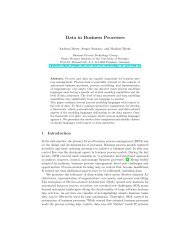
The result of queries (rules) 1 <strong>and</strong> 2 in Figure 6 against the process model<br />
in Figure 1 is shown in Figure 8 where all nodes between ”Obtain Customer<br />
Info” <strong>and</strong> ”Open Account” are included in the result. Since the activity ”Verify<br />
Customer ID” already resides on the path from ”Obtain Customer Info” to<br />
”Open Account” , the evaluation of path from ”Verify Customer ID” to ”Open<br />
Account” will not introduce new nodes or edges to the result.<br />
Obtain<br />
Customer<br />
Info<br />
Non-VIP<br />
Retrieve<br />
Full<br />
Customer<br />
Dtl<br />
VIP<br />
Analyze<br />
Customer<br />
Relation<br />
Prepare<br />
Prop. Doc<br />
Propose<br />
Account<br />
Opening<br />
Schedule<br />
Status<br />
Review<br />
Open Acc<br />
Status<br />
Review<br />
Verify<br />
Customer<br />
ID<br />
Open<br />
Account<br />
Fig. 8. Process graph matching rule 1<br />
We can notice in the result of query 2 (as shown in Figure 9) that nodes<br />
preceding the activities ”Submit Deposit” <strong>and</strong> ”Record Customer Info” were<br />
also included. This is due to the implicit inclusion of a start node with a path<br />
to ”Open Account”. This inclusion occurred because of the precedes between<br />
”Record Customer Info” <strong>and</strong> ”Open Account” as discussed in Section 3.
Obtain<br />
Customer<br />
Info<br />
Non-VIP<br />
Retrieve<br />
Full<br />
Customer<br />
Dtl<br />
VIP<br />
Analyze<br />
Customer<br />
Relation<br />
Propose<br />
Account<br />
Opening<br />
Receive<br />
customer<br />
request<br />
Identify<br />
Customer<br />
Info<br />
Select<br />
Deposit<br />
Service<br />
Submit<br />
Deposit<br />
Record<br />
Customer<br />
Info<br />
Prepare<br />
Prop. Doc<br />
Schedule<br />
Status<br />
Review<br />
Open Acc<br />
Status<br />
Review<br />
Verify<br />
Customer<br />
ID<br />
Open<br />
Account<br />
Fig. 9. Process graph matching rule 2<br />
Graph Reduction<br />
Reduction rules have been successfully used either as a major approach [22, 23],<br />
or an engineering approach [26, 19] to verify correctness of process models. We<br />
adopt the reduction approach to reduce the state space for model checking in<br />
a way to work around the state space explosion [3]. Unlike the aforementioned<br />
approaches which focused on simplifying the underlying control graph, our<br />
approach respects <strong>and</strong> depends on the set of activities included in the rule to be<br />
verified. So, the reduction result differs depending on the rule to be verified.<br />
We have already discussed the difference between precedes <strong>and</strong> leads to<br />
dependencies. As a result, the reduction rules applied must respect these dependencies.<br />
This is especially important when considering decision points<br />
(XOR/OR-splits) <strong>and</strong> merging behavior (XOR/OR-joins).<br />
– R1: Reduction of Activities, <strong>and</strong> intermediate events: all activities that are<br />
not of interest to the compliance rule (query) are removed.<br />
– R2: Reduction of Structured Blocks. A block of split gateway that is directly<br />
connected to a join gateway of the same type <strong>and</strong> both have no other<br />
connections is replaced with a sequence flow edge.<br />
– R3: Merging of similar gateways. if two splits or two joins of the same type<br />
follow each other, for example an XOR-split A is followed by XOR-split B<br />
<strong>and</strong> B has no other incoming edges, B is removed <strong>and</strong> the sequence flow<br />
edge between A <strong>and</strong> B. A inherits all outgoing sequence flow edges of B.<br />
– R4: Reduction of structured loops. Loops having an XOR/OR-join node as<br />
an input <strong>and</strong> an XOR/OR-split as an output with backward edge from split<br />
node to join node are reduced by removing the backward edge.<br />
– R5: Reduction of Single activity parallel blocks. Whenever an activity that<br />
is of interest to the compliance rule (query) lies in parallel block, after the<br />
reduction of other activities that are parallel to it, parallel block is removed<br />
<strong>and</strong> the activity is retained connected with nodes before <strong>and</strong> after the block.<br />
if the parallel block contains in only one of its branches activities of interest<br />
that are somehow in a nested structure, the direct edges from the AND-Split<br />
to the AND-join are removed.<br />
– R6: Reduction of Single output AND-Split <strong>and</strong> single input join nodes.<br />
Due to the nature of pattern matching based query processing of <strong>BPMN</strong>-Q<br />
(see [2] section 6), <strong>and</strong> to application of other reduction rules, a situation<br />
where an AND-Split with single outgoing edge or a join gateway that is
either preceded or followed by an Activity of interest to the query may<br />
occur. The rule replaces the node with a single sequence flow between the<br />
source of its incoming sequence flow <strong>and</strong> the destination of its outgoing<br />
sequence flow.<br />
– R7: Reduction of start events. Depending on whether the query contains<br />
start events (either explicitly by the user or implicitly added as described<br />
in 3, we reduce start events in case two or more start events are the input for<br />
an AND-join. We remove the set of start events along with sequence flow<br />
edges to the AND-join <strong>and</strong> the AND-join itself <strong>and</strong> introduce a single start<br />
event <strong>and</strong> a sequence flow edge from that event to the destination of the<br />
outgoing sequence flow edge of the AND-join.<br />
– R8: Reduction of single activity selection block. The application of this<br />
rule depends on the type of path operator the activity is involved in. The<br />
reduction rule is applicable only If this activity is involved in only leads to<br />
paths as a source, otherwise we cannot apply the rule.<br />
– R9: Reduction of <strong>BPMN</strong>-specific activities. This includes the MI activity,<br />
loop activity <strong>and</strong> ad-hoc activities. For MI <strong>and</strong> ad-hoc activities we assume<br />
that there is only one token produced from the activity after all running<br />
instances complete. In case of Loop activities we follow the mapping shown<br />
in [4].<br />
Rules from R1 to R4 are adapted from previous work using reduction rules to<br />
verify correctness [26, 19, 22]. Unlike other reduction approaches, the reduced<br />
graph always contains the set of activities mentioned in the query graph.<br />
Applying reduction rules to the process graph of Figure 8 will result in<br />
reduced graph shown in Figure 10. We elaborate more details on applying<br />
Obtain<br />
Customer<br />
Info<br />
Verify<br />
Customer<br />
ID<br />
Open<br />
Account<br />
Fig. 10. Reduced graph for rule 1<br />
reduction rules to the result of query 2 shown in Figure 9. R1 is applied to<br />
remove all activities <strong>and</strong> intermediate events that are not of interest to the<br />
compliance rule. The result is shown in Figure 11 (a). Applying rules R2, R3 to<br />
the graph resulting from (a) yields the reduced graph in (b). Applying R2 again<br />
removes the parallel block immediately before the ”Open Account” activity. A<br />
special case of R5 (as discussed earlier) is applied where the direct edges from<br />
the first AND-Split to the AND-join are removed resulting in graph (c). A final<br />
application of R6 produces graph in (d).<br />
Generation of <strong>Temporal</strong> <strong>Logic</strong> Formulae<br />
Linear <strong>Temporal</strong> <strong>Logic</strong> allows expressing formulae about the future of systems.<br />
In addition to logical connectors (¬, ∨, ∧, →, ⇔) <strong>and</strong> atomic propositions, it<br />
introduces temporal quantifiers (always, eventually, next, until). The temporal<br />
operator eventually is of direct correspondence to the leads to concept. On the
Submit<br />
Deposit<br />
Record<br />
Customer<br />
Info<br />
Open<br />
Account<br />
(a) Reduced graph after applying R1 on<br />
result of query 2<br />
Submit<br />
Deposit<br />
Record<br />
Customer<br />
Info<br />
Open<br />
Account<br />
(b) Reduced graph after applying R2<br />
<strong>and</strong> R3 on reduced graph from (a)<br />
Submit<br />
Deposit<br />
Record<br />
Customer<br />
Info<br />
Open<br />
Account<br />
(c) Reduced graph after applying R2<br />
<strong>and</strong> R5 on reduced graph from (b)<br />
Submit<br />
Deposit<br />
Record<br />
Customer<br />
Info<br />
Open<br />
Account<br />
(d) Reduced graph after applying R6<br />
reduced graph from (c)<br />
Fig. 11. Reduced graph for rule 2<br />
other h<strong>and</strong>, the translation of the precedes into a temporal expression in LTL<br />
would be complex. We used Past linear time temporal logic PLTL [17, 28] as it<br />
has introduced the counterpart temporal quantifiers (always in past, once in the<br />
past, previous sate, since) to allow expressing formulae about the past states<br />
of a system. Although these quantifier did not increase the expressiveness of<br />
LTL, it made expressing formulae about the past exponentially succinct than in<br />
pure-future LTL [16]. Since the representation of these temporal quantifiers is<br />
not st<strong>and</strong>ardized, we mention the notation we use throughout this paper. For<br />
future states G(all future states), X(next state), F(eventually), U(Until). For past<br />
states H(all past states), Y(previous state), O(Once in the past), S(Since). It is<br />
straightforward to relate the concept of precedes to the temporal operator O <strong>and</strong><br />
the concept of leads to to the operator F.<br />
The generation of PLTL formulae from queries is straight forward. The following<br />
listing summarizes the translation into PLTL.<br />
– A leads to B is translated to A →F(B).<br />
– A precedes B is translated to B →O(A).<br />
All generated formulae for different path constructs are conjuncted together <strong>and</strong><br />
surrounded by the G operator to express the meaning of in all possible execution<br />
scenarios, be sure that the formulae are satisfied.<br />
Query of rule 1 will generate the following temporal formula
G( (Obtain Customer Info →F(Open Account)) ∧ (Verify Customer ID<br />
→F(Open Account)))<br />
Model checking this formula against reduced graph of Figure 10 will result<br />
in success i.e. the process model complies with the rule. Query of rule 2 will<br />
generate the following temporal formula<br />
G( (submit deposit →F(record customer info)) ∧<br />
(open account →O(record customer info)))<br />
Model checking this formula against reduced graph of Figure 11 will fail i.e.<br />
there are some execution scenarios that do not satisfy this formula.<br />
Petri Net <strong>and</strong> State Space Generation<br />
We need to generate, from the (reduced) graph, the finite state machine that<br />
will be, along with the PLTL expression, the input to model checker. In fact, we<br />
need to be sure that the state machine is finite, otherwise model checking is not<br />
feasible [3, 8]. In order to generate the state machine <strong>and</strong> determine its finiteness,<br />
we have to give formal execution semantics for the different constructs of <strong>BPMN</strong>.<br />
We follow the approach introduced in [4]. In this approach a mapping of a<br />
subset of <strong>BPMN</strong> constructs (for example OR-join is not addressed) to Petri nets<br />
is given. We have implemented their algorithm in our tool, as will be shown<br />
later. Generation of state machine from the Petri net is then obtained by the<br />
reachability graph of the net. Finiteness of the state machine reduces to the<br />
boundedness of the net, so utilizing a Petri net tool to determine this property.<br />
Figure 12 is the generated Petri net for the reduced graph of Figure 11.<br />
Start<br />
event<br />
Submit<br />
Deposit<br />
Submit_deposit_complete<br />
Record_customer_info_complete<br />
Record<br />
Customer<br />
Info<br />
Open<br />
Account<br />
Open_account_complete<br />
Fig. 12. Petri net for reduced process graph of Figure 11<br />
Output places of Transitions corresponding to activities are of interest to<br />
indicate the execution of the activity —see labeled places of Figure 12. Further<br />
reductions of the level of a Petri net are possible provided that these places are<br />
not merged.<br />
Table 1 shows the average running time of model checker for checking rule 2<br />
with <strong>and</strong> without using reduction. The query of rule 2 matched 5 process models<br />
in the repository. One of them was excluded from model checking because it<br />
suffered from a deadlock.
Process Model Id MC without reduction MC with reduction Reduction time<br />
13 151 ms 89 ms 21 ms<br />
34 52 ms 31 ms 0 ms<br />
35 52 ms 37 ms 11 ms<br />
40 68 ms 47 ms 5 ms<br />
Table 1. Comparison of average running time of model checker with <strong>and</strong> without using<br />
reduction<br />
5 Related Work<br />
According to [21] checking for compliance can occur either after-the-fact or beforethe-fact.<br />
Manually auditing processes is one way to check compliance in an afterthe-fact<br />
fashion. An automated approach to detect violations from workflow<br />
logs using LTL checkers was introduced in [25].<br />
Before-the -fact approaches can be further categorized as either (a) complianceaware<br />
design or (b) post design verification. [21] is an example for complianceaware<br />
design. Here, control objectives are modeled independently, that way<br />
addressing conflicting requirements between processes <strong>and</strong> regulations. The<br />
authors build their approach on a requirements modeling framework that later<br />
on propagates (forces) these requirements onto business processes. Another approach<br />
to guarantee compliance by design is given in [14], introducing PENE-<br />
LOPE as a declarative language to capture obligations <strong>and</strong> permissions imposed<br />
by business policies (sequencing <strong>and</strong> timing constraints between activities) <strong>and</strong><br />
later on automatically generate business processes that are, by design, compliant<br />
with these policies. The same authors have discussed in [13] the importance<br />
of explicitly modeling business rules as an enabler of flexibility <strong>and</strong> generation<br />
of less complex business processes. A more recent approach to compliance by<br />
design is introduced in [20] which can be seen as an extension of [21] with<br />
a special focus on assisting the process designer to create compliant business<br />
processes.<br />
We categorize our work as before-the-fact <strong>and</strong> post design. Other work in this<br />
category is briefly discussed. The Formal Contract Language (FCL) was introduced<br />
in [15] to formally measure the compliance between a business contract<br />
<strong>and</strong> a business process. In [12] an approach to check compliance of business<br />
processes <strong>and</strong> the resolution of violations was introduced. The paper defines<br />
Semantic Process Networks (SPN), where each activity is further annotated<br />
with effect predicates. Rules are then verified against this network. In [18], a<br />
formal approach based on model checking was given to check for compliance<br />
of processes defined in BPEL against constraints defined in the Business Property<br />
Specification Language (BPSL) that are translated to LTL. The approach is<br />
close to ours. However, we are able to express constraints in PLTL rather than<br />
LTL only, which gives our approach more expressiveness over the other. Similar<br />
work that verifies BPEL processes is in [27] where authors propose their own<br />
language PROPOLS to capture patterns to be checked against a business process.<br />
The approach depends on transforming PROPOLS expressions into FSAs<br />
<strong>and</strong> BPEL into LTS/FSA <strong>and</strong> check the language inclusion between the two
FSAs. Work in [9–11] defines a set of visual patterns using the Process Pattern<br />
Specification Language (PPSL). These patterns are used to express constraints<br />
against UML Activity Diagrams. PPSL patterns are then translated into PLTL<br />
formulae. The approach is the closest to ours from the point of expressiveness<br />
i.e. it supports reasoning with PLTL, yet we offer a small set of constructs to express<br />
the same set of concepts. Similar work on verification of properties against<br />
UML Activity Diagrams has been accomplished earlier by Erik et al in [5, 7, 6],<br />
where they offered their own formalization of ADs <strong>and</strong> used model checking to<br />
verify properties against them.<br />
<strong>Using</strong> queries for generating PLTL formulae, the retrieval of sub graphs to<br />
be tested <strong>and</strong> the application of reduction rules for simplifying the state space<br />
are unique properties of our approach.<br />
6 Conclusion<br />
In this paper we have presented an approach for compliance checking for <strong>BPMN</strong><br />
process models using <strong>BPMN</strong>-Q queries. As centerpiece of the analysis, a model<br />
checker is used. The approach is not limited to <strong>BPMN</strong> process models, it can be<br />
applied to any process modeling language provided that it has a formal execution<br />
semantics. This approach is effective under the assumption that business<br />
process models really reflect the way business is carried out.<br />
We have implemented a prototypical tool chain for our approach. As process<br />
modeling environment we use Oryx 4 , a web-based <strong>BPMN</strong> editor developed in<br />
our research group. We implemented a Petri net generator as an integrated<br />
component in <strong>BPMN</strong>-Q. LoLA [24] 5 is used for checking boundedness <strong>and</strong><br />
absence of deadlocks. LoLA is also used for producing the finite state machine.<br />
We implemented a PLTL generator returning the temporal logic formulae. As<br />
model checker we opted for NuSMV 6 due to its support for PLTL expressions.<br />
In the current version of our approach, we are able to give yes/no answers<br />
for the compliance between rule(s) <strong>and</strong> process models. As a limitation of our<br />
approach, the detailed analysis provided by the model checker in the case of noncompliance<br />
cannot be taken advantage of. This is due to the fact that we applied<br />
reductions. This means that generated counter examples by model checker do<br />
not reflect real execution scenarios in process models. An important assumption<br />
behind the use of reduction rules is the relaxation of usage of temporal operators<br />
next X, <strong>and</strong> previous Y in queries. It has been pointed in literature that the X<br />
operator is of little interest when verifying properties of process models [5, 7].<br />
Currently, most of research in compliance checking focuses on verification<br />
of control flow aspects. As a future work, we intend to extend <strong>BPMN</strong>-Q with<br />
the capability of querying data objects <strong>and</strong> verification of their states as preconditions<br />
for activities.<br />
4 See http://bpt.hpi.uni-potsdam.de/Oryx/<br />
5 See http://wwwteo.informatik.uni-rostock.de/ls tpp/lola/<br />
6 See http://nusmv.irst.itc.it/
References<br />
1. Sarbanes-Oxley Act of 2002. Public Law 107-204, (116 Statute 745), United States Senate<br />
<strong>and</strong> House of Representatives in Congress, 2002.<br />
2. A. Awad. <strong>BPMN</strong>-Q: A Language to Query Business Processes. In EMISA, pages<br />
115–128, 2007.<br />
3. E. M. Clarke, O. Grumberg, <strong>and</strong> D. A. Peled. Model <strong>Checking</strong>. MIT Press, 1999.<br />
4. R. M. Dijkman, M. Dumas, <strong>and</strong> C. Ouyang. Semantics <strong>and</strong> Analysis of Business<br />
Process Models in <strong>BPMN</strong>. Information <strong>and</strong> Software Technology (IST), 2008.<br />
5. H. Eshuis. SEMANTICS AND VERIFICATION OF UML ACTIVITY DIAGRAMS<br />
FOR WORKFLOW MODELLING. PhD thesis, Centre for Telematics <strong>and</strong> Information<br />
Technology (CTIT) University of Twente, 2002.<br />
6. R. Eshuis. Symbolic model checking of uml activity diagrams. ACM Trans. Softw.<br />
Eng. Methodol., 15(1):1–38, 2006.<br />
7. R. Eshuis <strong>and</strong> R. Wieringa. Tool support for verifying uml activity diagrams. IEEE<br />
Transactions on Software Engineering, 30(7):437–447, 2004.<br />
8. J. Esparza. Decidability of model checking for infinite-state concurrent systems. Acta<br />
Informatica, 34(2):85–107, 1997.<br />
9. A. Förster, G. Engels, <strong>and</strong> T. Schattkowsky. Activity diagram patterns for modeling<br />
quality constraints in business processes. In MoDELS, pages 2–16, 2005.<br />
10. A. Förster, G. Engels, T. Schattkowsky, <strong>and</strong> R. V. D. Straeten. A pattern-driven<br />
development process for quality st<strong>and</strong>ard-conform business process models. In<br />
IEEE Symposium on Visual Languages <strong>and</strong> Human-Centric Computing VL, 2006.<br />
11. A. Förster, G. Engels, T. Schattkowsky, <strong>and</strong> R. V. D. Straeten. Verification of business<br />
process quality constraints based on visual process patterns. In TASE, pages 197–208.<br />
IEEE Computer Society, 2007.<br />
12. A. Ghose <strong>and</strong> G. Koliadis. Auditing business process compliance. In Service-Oriented<br />
Computing ICSOC 2007, pages 169–180. Springer Berlin / Heidelberg, 2007.<br />
13. S. Goedertier <strong>and</strong> J. Vanthienen. Compliant <strong>and</strong> Flexible Business Processes with<br />
Business Rules. In 7th Workshop on Business Process Modeling, 2006.<br />
14. S. Goedertier <strong>and</strong> J. Vanthienen. Designing Compliant Business Processes from<br />
Obligations <strong>and</strong> Permissions, 2nd Workshop on Business Processes Design (BPD’06),<br />
Proceedings. In Business Process Management Workshops, 2006.<br />
15. G. Governatori, Z. Milosevic, <strong>and</strong> S. Sadiq. <strong>Compliance</strong> checking between business<br />
processes <strong>and</strong> business contracts. In EDOC ’06, pages 221–232, Washington, DC,<br />
USA, 2006. IEEE Computer Society.<br />
16. S. Hornus <strong>and</strong> P. Schnoebelen. On solving temporal logic queries. In AMAST ’02:<br />
Proceedings of the 9th International Conference on Algebraic Methodology <strong>and</strong> Software<br />
Technology, pages 163–177, London, UK, 2002. Springer-Verlag.<br />
17. F. Laroussinie <strong>and</strong> P. Schnoebelen. A hierarchy of temporal logics with past. Theoretical<br />
Computer Science, 148(2):303–324, 1995.<br />
18. Y. Lui, S. Mller, <strong>and</strong> K. Xu. A static compliance-checking framework for business<br />
process models. IBM SYSTEMS JOURNAL, 46(2):335–362, 2007.<br />
19. J. Mendling. Detection <strong>and</strong> Prediction of Errors in EPC Business Process Models. PhD<br />
thesis, Institute of Information Systems <strong>and</strong> New Media Vienna University of Economics<br />
<strong>and</strong> Business Administration (WU Wien) Austria, May 2007.<br />
20. S. S. R. Lu <strong>and</strong> G. Governatori. <strong>Compliance</strong> aware business process design. In 3rd<br />
International Workshop on Business Process Design (BPD07), in Conjunction with 5th<br />
International Conference on Business Process Management, 2007.<br />
21. S. W. Sadiq, G. Governatori, <strong>and</strong> K. Namiri. Modeling control objectives for business<br />
process compliance. In BPM, pages 149–164, 2007.
22. W. Sadiq <strong>and</strong> M. E. Orlowska. Applying graph reduction techniques for identifying<br />
structural conflicts in process models. In CAiSE ’99, pages 195–209, London, UK,<br />
1999. Springer-Verlag.<br />
23. W. Sadiq <strong>and</strong> M. E. Orlowska. Analyzing process models using graph reduction<br />
techniques. Inf. Syst., 25(2):117–134, 2000.<br />
24. K. Schmidt. Lola a low level analyser. In Application <strong>and</strong> Theory of Petri Nets 2000:<br />
21st International Conference, ICATPN 2000, Aarhus, Denmark, June 2000. Proceedings,<br />
volume 1825, page 465. Springer Berlin / Heidelberg, 2000.<br />
25. W. M. P. van der Aalst, H. T. de Beer, <strong>and</strong> B. F. van Dongen. Process mining <strong>and</strong><br />
verification of properties: An approach based on temporal logic. In OTM Conferences<br />
(1), pages 130–147, 2005.<br />
26. B. F. van Dongen, W. M. P. van der Aalst, <strong>and</strong> H. M. W. Verbeek. Verification of epcs:<br />
<strong>Using</strong> reduction rules <strong>and</strong> petri nets. In CAiSE, pages 372–386, 2005.<br />
27. J. Yu, T. P. Manh, J. Han, Y. Jin, Y. Han, <strong>and</strong> J. Wang. Pattern based property specification<br />
<strong>and</strong> verification for service composition. In WISE, pages 156–168, 2006.<br />
28. L. Zuck. Past <strong>Temporal</strong> <strong>Logic</strong>. PhD thesis, Weizmann Intitute, Rehovet, Israel, August<br />
1986.