Keyless Entry User Guide - Procare Software
Keyless Entry User Guide - Procare Software
Keyless Entry User Guide - Procare Software

You also want an ePaper? Increase the reach of your titles
YUMPU automatically turns print PDFs into web optimized ePapers that Google loves.
TM<br />
ProCare<br />
management system<br />
<strong>Keyless</strong> <strong>Entry</strong><br />
System<br />
See reverse side for Wiring Diagram and<br />
Product Specifications<br />
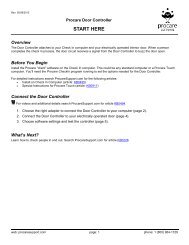
Installation Instructions<br />
Before you begin...<br />
Connecting the <strong>Keyless</strong> <strong>Entry</strong> System (KES) is not complicated; however, unless you are experienced in doing<br />
so, electrical connections should be made by a qualified technician. This unit is not intended for after hours<br />
security. A dead bolt or similar device will be needed when the building is closed.<br />
Each KES is shipped with the following components. Verify that your box contains:<br />
a.) Keypad with short attached cable, cable coupler, and long (8 wire) cable with RJ45 connectors.<br />
b.) Relay Box<br />
c.) Chime (Doorbell) Kit with doorbell, transformer and two (2) manual override buttons,<br />
d.) Wire with RJ11 connectors e.) RJ11 to Serial Adapter f.) Serial to USB Adapter & USBgear mini CD<br />
g.) <strong>Procare</strong> CD and Getting Started <strong>Guide</strong><br />
Please set up and test these components on a table top prior to mounting them in their final locations.<br />
Mounting the components (order is not important).<br />
1 Mount the keypad in the desired location. Be sure to allow a cable feed-through hole. The keypad<br />
should be in a location (indoors or out) that does not receive direct sun or rain. Attach the short<br />
cable on the keypad to the cable coupler then to the long RJ45 cable (supplied) or substitute<br />
your own straight through CAT-5 network cable.<br />
2 Mount the relay box in a protected indoor location, such as the attic of the building. Again, keep in<br />
mind the RJ11 cable (provided) will need to reach from the relay box to the computer.<br />
3 Mount the doorbell transformer in a protected indoor location. Make sure a standard 110V power outlet<br />
is within reach of the transformer.<br />
4 Mount the doorbell in an audible, central, location.<br />
5 Mount the door strike or magnetic lock unit per the manufacturer’s instructions.<br />
6 Mount the manual override button(s) in the desired location(s).<br />
Making the electrical connections (If you have not already done so, TURN OFF ELECTRICITY).<br />
7 Connect the long RJ45 cable coming from the keypad to the Relay Box terminal marked “Keypad.”<br />
8 Connect a 110V power supply to the doorbell transformer.<br />
9 Using 20-2 gauge wire, connect the doorbell transformer to the<br />
relay box using the terminal marked “Transformer.”<br />
10 Using 20-3 gauge wire, connect the doorbell to the relay<br />
box using the terminal marked “Doorbell.”<br />
11 Using 20-2 gauge wire, connect the door strike and manual<br />
override buttons (if desired) to the relay box using the<br />
terminal marked “Door Control Circuit”.<br />
12 See previous page for details. Install driver from the USBGear<br />
mini CD. Then connect USB-Serial adapter to computer’s USB<br />
port. (Serial-RJ11 adapter should already be attached).<br />
13 Connect RJ11 cable to relay box terminal marked<br />
“Computer Serial Port.” Attach other end of cable to RJ11<br />
9 10 11 13 7<br />
adapter at computer. See Getting Started <strong>Guide</strong> for installation of <strong>Procare</strong> CD and software use.<br />
Sales: 1-800-338-3884 www.procaresoftware.com Support: 1-800-964-1729<br />
rev 4/06/2009