3D network simulations of paper structure - Innventia.com
3D network simulations of paper structure - Innventia.com
3D network simulations of paper structure - Innventia.com

You also want an ePaper? Increase the reach of your titles
YUMPU automatically turns print PDFs into web optimized ePapers that Google loves.
PAPER PHYSICS<br />
et al. 2007; Switzer et al. 2004; Lindström, Uesaka 2008.<br />
Pulp fibers were modeled as multilink chains <strong>of</strong> rigid<br />
cylindrical segments with circular cross-section,<br />
immersed into Newtonian liquid. Fiber chains can bend<br />
and twist due to joints between segments. Different cases<br />
<strong>of</strong> liquid motion were considered, including simple<br />
drainage under gravity and external pressure, (see<br />
Miettinen et al. 2007; Switzer et al. 2004), and <strong>com</strong>plex<br />
water movement in different sections <strong>of</strong> roll-blade<br />
formers, (Lindström, Uesaka 2008; Lindstrom et al.,<br />
2009). These models suffer some disadvantages such as<br />
the limitations <strong>of</strong> rigid segments which do not permit the<br />
same fiber bending, the output <strong>network</strong>s have low density<br />
and higher thickness. However, these methods can be<br />
used for generating pulp webs <strong>of</strong> low consistency, and<br />
thus can simulate forming situations corresponding to the<br />
wet web before the wet pressing section in the <strong>paper</strong><br />
machine.<br />
The main goal <strong>of</strong> the present work is to develop a<br />
numerical approach to build a <strong>3D</strong> artificial hand sheet<br />
and machine sheet fiber <strong>network</strong>s with prescribed<br />
thickness and apparent density, consisting <strong>of</strong> collapsed<br />
and non-collapsed fibers, fines and fillers. We can take a<br />
simulated <strong>structure</strong> made by using multilink chains <strong>of</strong><br />
rigid cylindrical segments as fibers and abstract the <strong>3D</strong><br />
<strong>structure</strong> <strong>of</strong> the formed <strong>paper</strong> sheet. The abstraction is by<br />
using the center lines <strong>of</strong> the fibers and redecorating their<br />
thicknesses and widths to develop a fiber model with<br />
prismatic elements <strong>com</strong>prising the fibers. The fibers are<br />
also considered to be hollow to allow for the lumens and<br />
can be <strong>com</strong>pressed in a wet pressing simulation to<br />
generate a ‘final’ <strong>structure</strong>. In the following, we will<br />
describe our method <strong>of</strong> generating the <strong>paper</strong> <strong>structure</strong> and<br />
show how it is applied to a random ‘handsheet’ <strong>structure</strong><br />
and a realistic, simulated sheet formed using a twin wire<br />
roll former with blades. The <strong>structure</strong>s are then analyzed<br />
for their mechanical properties (in this case, the elastic<br />
modulus).<br />
Fiber <strong>network</strong> Generation<br />
Hand Sheet Formation<br />
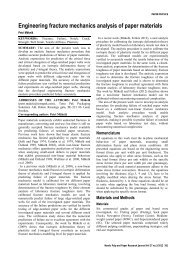
A set <strong>of</strong> objects is defined for the simulation, which<br />
includes objects <strong>of</strong> three types: fibers, fines or fillers.<br />
These are characterized by their geometrical parameters<br />
which include length, width and thickness, their<br />
distributions and type <strong>of</strong> cross-section i.e. collapsed or<br />
non-collapsed, as in Fig 1. Fiber type 1a has only one<br />
finite element in thickness direction. This type was<br />
usually used to describe fines and fillers. Fiber types 1b<br />
and 1c have arbitrary number <strong>of</strong> elements in all three<br />
directions (length, width, thickness). Non-collapsed fiber<br />
type 1d has always one element in the thickness <strong>of</strong> fiber<br />
wall and arbitrary number <strong>of</strong> elements in other two<br />
directions. It is possible to include curl and kink <strong>of</strong> fibers<br />
by suitable modifications <strong>of</strong> these elementary <strong>structure</strong>s,<br />
although this was not implemented in the current<br />
simulation.<br />
The first step <strong>of</strong> the simulation is to generate an initial<br />
<strong>structure</strong>. Handsheet formation can be simulated by<br />
simply placing fibers (or objects) randomly in space<br />
(a)<br />
(c)<br />
(b)<br />
(d)<br />
Fig 1. Configurations <strong>of</strong> fibers used in the model<br />
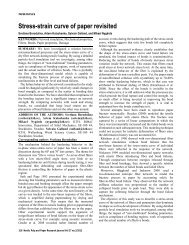
Frequency<br />
0,45<br />
0,40<br />
0,35<br />
0,30<br />
0,25<br />
0,20<br />
0,15<br />
0,10<br />
0,05<br />
0,00<br />
Hardwood Pulp<br />
0,5 0,9 1,4 2,0 2,7<br />
Fiber length, mm<br />
Fig 2. Examples <strong>of</strong> fiber length distributions for s<strong>of</strong>twood and<br />
hardwood pulps<br />
according to their distribution in the furnish. An example<br />
<strong>of</strong> such distributions for hard wood and s<strong>of</strong>t wood pulps<br />
are shown in Fig 2.<br />
The second step is location <strong>of</strong> centers <strong>of</strong> objects in Z<br />
direction. Each new object has Z coordinate taking into<br />
account all objects already generated and located below<br />
this particular one. All points <strong>of</strong> such line have the same<br />
Z-coordinate.<br />
The third step is the generation <strong>of</strong> finite element grid in<br />
each object according to type <strong>of</strong> object cross-section and<br />
its dimensions. The topology <strong>of</strong> finite elements (shape<br />
and local numbering <strong>of</strong> nodes) should correspond to finite<br />
element s<strong>of</strong>tware used in the following steps. In our case<br />
this was the 8-node hexahedron solid element in the LS-<br />
DYNA Explicit program.<br />
Nordic Pulp and Paper Research Journal Vol 27 no.2/2012 257