GMH8/GDH8 - Amana
GMH8/GDH8 - Amana
GMH8/GDH8 - Amana

You also want an ePaper? Increase the reach of your titles
YUMPU automatically turns print PDFs into web optimized ePapers that Google loves.
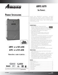
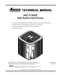
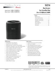
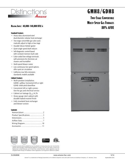
Heating Input: 40,000–140,000 BTU/h<br />
Standard Features<br />
• Heavy-duty aluminized-steel<br />
dual-diameter, tubular heat exchanger<br />
• Two-stage convertible gas valve automatically<br />
adjust to high or low stage<br />
• Durable Silicon Nitride igniter<br />
• Quiet single speed draft inducer<br />
• Self-diagnostic control board<br />
with constant memory fault code<br />
• Color-coded low-voltage terminals<br />
with provisions for electronic air<br />
cleaner and humidifier<br />
• Multi-speed blower motor<br />
• Low continuous fan speed options<br />
offer quiet air circulation<br />
• California Low NOx emissions<br />
standards models available<br />
Cabinet Features<br />
• Multi-position installation:<br />
<strong>GMH8</strong>: upflow, horizontal left or right<br />
<strong>GDH8</strong>: dedicated downflow<br />
• Convenient left or right connection<br />
for gas and electrical service<br />
• Cabinet air leakage (Q Leak ) ≤ 2%<br />
• Heavy-gauge steel cabinet with<br />
durable baked-enamel finish<br />
• Fully insulated heat exchanger<br />
and blower section<br />
®<br />
®<br />
<strong>GMH8</strong>/<strong>GDH8</strong><br />
Two-Stage Convertible<br />
Multi-Speed Gas Furnaces<br />
80% AFUE<br />
Contents<br />
Nomenclature........................................ 2<br />
Product Specifications........................... 3<br />
Dimensions............................................ 5<br />
Airflow Data........................................... 7<br />
Wiring Diagram.................................... 10<br />
Accessories........................................... 11<br />
* Complete warranty details available from you local dealer or at www.amana-hac.com. To receive the<br />
Lifetime Heat Exchanger Limited Warranty (good for as long as you own your home), 10-Year Unit<br />
Replacement Limited Warranty and 10-Year Parts Limited Warranty, online registration must be<br />
completed within 60 days of installation. Online registration is not required in California or Québec.<br />
SS-D<strong>GMH8</strong> www.amana-hac.com 5/14<br />
<strong>Amana</strong>® is a trademark of Maytag Corporation or its related companies and used under license to Goodman Company, L.P., Houston, Texas. Supersedes 4/13
Product Specifications<br />
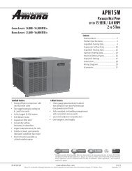
Nomenclature<br />
Goodman Furnace Nomenclature (13 Digits)<br />
Brand<br />
G-‐ Goodman<br />
Configuration<br />
M -‐ Upflow/Horizontal<br />
C -‐ Downflow/Horizontal<br />
K -‐ Dedicated Upflow<br />
D -‐ Dedicated Downflow<br />
Gas Vale / Motor<br />
E-‐ Convertible 2 Stage / High Efficiency<br />
H -‐ Convertible 2 Stage / Single Speed<br />
S -‐ Single Stage / Single Speed<br />
G M H 80 060 3 A N A A<br />
1 2 3 4,5 6,7,8 9 10 11 12 13<br />
Minor Revision<br />
A -‐ Initial Release<br />
B -‐ 1st Revision<br />
Major Revision<br />
A -‐ Initial Release<br />
B -‐ 1st Revision<br />
NOx<br />
N -‐ Natural Gas<br />
X -‐ Low NOx<br />
Cabinet Width<br />
A -‐ 14" C -‐ 21"<br />
AFUE B -‐ 17½" D -‐ 24½"<br />
97 -‐ 97% AFUE<br />
80 -‐ 80% AFUE Maximum CFM<br />
3 -‐ 1200 CFM<br />
MBTU/h<br />
4 -‐ 1600 CFM<br />
40 -‐ 40,000 100 -‐ 100,000 5 -‐ 2000 CFM<br />
60 -‐ 60,000 120 -‐ 120,000<br />
80 -‐ 80,000<br />
2 www.amana-hac.com SS-D<strong>GMH8</strong>
Product Specifications<br />
Specifications — <strong>GMH8</strong><br />
Heating Capacity<br />
<strong>GMH8</strong><br />
0403A*B<br />
<strong>GMH8</strong><br />
0603A*B<br />
<strong>GMH8</strong><br />
0604B*B<br />
<strong>GMH8</strong><br />
0803B*B<br />
<strong>GMH8</strong><br />
0804B*B<br />
<strong>GMH8</strong><br />
0805C*B<br />
<strong>GMH8</strong><br />
1005C*B<br />
<strong>GMH8</strong><br />
1205D*B<br />
<strong>GMH8</strong><br />
1405D*B<br />
Input 40,000 60,000 60,000 80,000 80,000 80,000 100,000 120,000 140,000<br />
Natural Gas Output 32,000 48,000 48,000 64,000 64,000 64,000 80,000 96,000 112,000<br />
LP Gas Output 32,000 48,000 48,000 64,000 64,000 64,000 80,000 96,000 96,000<br />
AFUE ¹ 80 80 80 80 80 80 80 80 80<br />
Available AC @ 0.5” ESP 3 3 4 3 4 5 5 5 5<br />
Temperature Rise Range (°F) 25 - 55 20 - 50 20 - 50 35 - 65 35 - 65 35 - 65 35 - 65 40 - 70 40 - 70<br />
Circulator Blower<br />
Size (D x W) 10” x 6” 10” x 6” 10” x 8” 10” x 8” 10” x 8” 10” x 10” 10” x 10” 11” x 10” 11” x 10”<br />
Horsepower @1075 RPM ⅓ ⅓ ½ ⅓ ½ ½ ½ ¾ ¾<br />
Speed 4 4 4 4 4 4 4 4 4<br />
Vent Diameter ² 4" 4" 4" 4" 4" 4" 4" 4" 4"<br />
No. of Burners 2 3 3 4 4 4 5 6 6<br />
Disposable Filter (in²) 580 580 770 580 770 960 960 960 960<br />
Electrical Data<br />
Min. Circuit Ampacity ³ 8.1 8.1 12.5 8.1 12.5 12.5 12.5 14.7 14.7<br />
Max. Overcurrent Device (amps) ⁴ 15 15 15 15 15 15 15 15 15<br />
Ship Weight (lbs) 86 90 98 106 107 114 118 132 132<br />
¹ DOE AFUE based upon Isolated Combustion System (ICS)<br />
² Vent and combustion air diameters may vary depending upon vent length. Refer to the latest editions of the National Fuel Gas Code NFPA 54/ANSI Z223.1<br />
(in the USA) and the Canada National Standard of Canada, CAN/CSA B149.1 and CAN/CSA B142.2 (in Canada).<br />
³ Minimum Circuit Ampacity = (1.25 x Circulator Blower Amps) + ID Blower amps. Wire size should be determined in accordance with National Electrical<br />
Codes. Extensive wire runs will require larger wire sizes.<br />
⁴ Maximum Overcurrent Protection Device refers to maximum recommended fuse or circuit breaker size. May use fuses or HACR-type circuit breakers of the<br />
same size as noted.<br />
Notes<br />
• All furnaces are manufactured for use on 115 VAC, 60 Hz, single-phase electrical supply.<br />
• Gas Service Connection ½” FPT<br />
• Important: Size fuses and wires properly and make electrical connections in accordance with the National Electrical Code and/or all existing local codes.<br />
SS-D<strong>GMH8</strong> www.amana-hac.com 3
Product Specifications<br />
Specifications — <strong>GDH8</strong><br />
<strong>GDH8</strong><br />
0403A*B<br />
<strong>GDH8</strong><br />
0603A*B<br />
<strong>GDH8</strong><br />
0804B*B<br />
<strong>GDH8</strong><br />
1005C*B<br />
Heating Capacity<br />
Input 40,000 60,000 80,000 100,000<br />
Natural Gas Output 32,000 48,000 64,000 80,000<br />
LP Gas Output 32,000 48,000 64,000 80,000<br />
AFUE ¹ 80 80 80 80<br />
Available AC @ 0.5” ESP 25 - 55 30-60 35-65 40-70<br />
Temperature Rise Range (°F) 3 3 4 5<br />
Circulator Blower<br />
Size (D x W) 10 X 6 10 X 6 10 X 8 10 X 10<br />
Horsepower @1075 RPM 1/3 1/3 1/2 3/4<br />
Speed 4 4 4 4<br />
Vent Diameter ² 4 4 4 4<br />
No. of Burners 2 3 4 5<br />
Disposable Filter (in²) 580 580 770 960<br />
Electrical Data<br />
Min. Circuit Ampacity ³ 8.5 8.5 12.9 12.9<br />
Max. Overcurrent Device (amps) ⁴ 15 15 15 15<br />
Ship Weight (lbs) 88 92 106 114<br />
¹ DOE AFUE based upon Isolated Combustion System (ICS)<br />
² Vent and combustion air diameters may vary depending upon vent length. Refer to the latest editions of the National Fuel Gas<br />
Code NFPA 54/ANSI Z223.1 (in the USA) and the Canada National Standard of Canada, CAN/CSA B149.1 and CAN/CSA B142.2<br />
(in Canada).<br />
³ Minimum Circuit Ampacity = (1.25 x Circulator Blower Amps) + ID Blower amps. Wire size should be determined in accordance<br />
with National Electrical Codes. Extensive wire runs will require larger wire sizes.<br />
⁴ Maximum Overcurrent Protection Device refers to maximum recommended fuse or circuit breaker size. May use fuses or<br />
HACR-type circuit breakers of the same size as noted.<br />
Notes<br />
• All furnaces are manufactured for use on 115 VAC, 60 Hz, single-phase electrical supply.<br />
• Gas Service Connection ½” FPT<br />
• Important: Size fuses and wires properly and make electrical connections in accordance with the National Electrical Code and/<br />
or all existing local codes.<br />
4 www.amana-hac.com SS-D<strong>GMH8</strong>
Product Specifications<br />
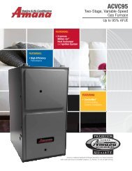
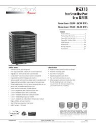
<strong>GMH8</strong> Dimensions<br />
Alt. Alt. Gas Inlet<br />
1¾” 1-3/4”<br />
A<br />
B<br />
1-7/16” 1⁷⁄₁₆”<br />
27-7/8” 27⅞”<br />
33-3/8” 33⅜”<br />
Alt. Gas Inlet<br />
High High-Voltage Inlet<br />
20”<br />
23-5/16” 23⁵⁄₁₆”<br />
Alt. High Voltage<br />
Low-Voltage Voltage Inlet<br />
13-1/4” 13¼”<br />
Alt. LowVoltage<br />
23 23¾” 3/4”<br />
28”<br />
Model A B Model A B<br />
<strong>GMH8</strong>0403A*B 14” 12½” <strong>GMH8</strong>0805C*B 21” 19½”<br />
<strong>GMH8</strong>0603A*B 14” 12½” <strong>GMH8</strong>1005C*B 21” 19½”<br />
<strong>GMH8</strong>0604B*B 17½” 16” <strong>GMH8</strong>1205D*B 24½” 23”<br />
<strong>GMH8</strong>0803B*B 17½” 16” <strong>GMH8</strong>1405D*B 24½” 23”<br />
<strong>GMH8</strong>0804B*B 17½” 16”<br />
Notes<br />
• Line voltage wiring and low-voltage wiring can enter through the right or left side of furnace.<br />
• Conversion kits for high-altitude (4500+ ft) natural gas operation are available. Contact your Goodman distributor or dealer for details.<br />
Minimum Clearances to Combustible Materials<br />
Sides Rear Front¹<br />
SW<br />
Vent²<br />
1” 0” 3” 6” 1” 1”<br />
¹ 24” clearance for serviceability recommended.<br />
² Single Wall Vent (SW) to be used only as a connector. Refer to the latest editions of the National Fuel Gas Code NFPA 54/ ANSI Z223.1 (in the<br />
USA) and the Canada National Standard of Canada, CAN/CSA B149.1 and CAN/CSA B142.2 (in Canada).<br />
Note: <strong>GMH8</strong> approved for line contact in the horizontal position.<br />
B<br />
Top<br />
SS-D<strong>GMH8</strong> www.amana-hac.com 5
Product Specifications<br />
PRODUCT DIMENSIONS<br />
<strong>GDH8</strong> Dimensions<br />
<strong>GDH8</strong><br />
19⅝”<br />
28”<br />
A<br />
B<br />
High Voltage<br />
Electrical<br />
Low Voltage<br />
Electrical<br />
High-Voltage<br />
Electrical<br />
Low-Voltage<br />
Electrical<br />
Gas Inlet<br />
33-3/8” 33⅜”<br />
11⅜”<br />
18⅜”<br />
Model A B Non-Combustible Floor Base<br />
<strong>GDH8</strong>0403A*B 14” 12½” SBT14<br />
NON-COMBUSTIBLE<br />
MODEL A B<br />
<strong>GDH8</strong>0603A*B 14” 12½” FLOOR BASE SBT14<br />
<strong>GDH8</strong>0804B*B <strong>GDH8</strong>0453AX 17½” 16” SBT17<br />
14 12 1/2 SBT14<br />
<strong>GDH8</strong>1005C*B <strong>GDH8</strong>0703AX 21” 19½” SBT21<br />
Notes<br />
<strong>GDH8</strong>0904BX 17 1/2 16 SBT17<br />
• Line voltage wiring and low-voltage wiring can enter through the right or left side of furnace.<br />
• Conversion kits for high-altitude (4500+ ft) natural gas operation are available. Contact your Goodman distributor or dealer<br />
for details. <strong>GDH8</strong>1155CX 21 19 1/2 SBT21<br />
• Installer must supply the following gas line fittings, according to which entrance is used:<br />
All dimensions are in inches.<br />
◊ Left: One 90º street elbow; one 2½” pipe nipple; one 90º elbow; straight pipe; one ground joint union<br />
◊ Right: Straight pipe to reach gas valve<br />
Minimum Clearances to Combustible Materials<br />
Sides Rear Front¹<br />
SW<br />
Vent²<br />
1” 0” 3” 6” 1” 1”<br />
¹ 24” clearance for serviceability recommended.<br />
² Single Wall Vent (SW) to be used only as a connector. Refer to the latest editions of the National Fuel Gas Code<br />
NFPA 54/ ANSI Z223.1 (in the USA) and the Canada National Standard of Canada, CAN/CSA B149.1 and CAN/CSA<br />
B142.2 (in Canada).<br />
B<br />
Top<br />
5<br />
6 www.amana-hac.com SS-D<strong>GMH8</strong>
Product Specifications<br />
<strong>GMH8</strong> Airflow Data<br />
(CFM & Temperature Rise vs. External Static Pressure)<br />
Model<br />
<strong>GMH8</strong><br />
0403A*B<br />
<strong>GMH8</strong><br />
0603A*B<br />
<strong>GMH8</strong><br />
0604B*B<br />
<strong>GMH8</strong><br />
0803B*B<br />
<strong>GMH8</strong><br />
0804B*B<br />
<strong>GMH8</strong><br />
0805C*B<br />
<strong>GMH8</strong><br />
1005C*B<br />
<strong>GMH8</strong><br />
1205D*B<br />
<strong>GMH8</strong><br />
1405D*C<br />
¹ @ 0.5” ESP<br />
Motor<br />
Speed<br />
Tons<br />
AC¹<br />
External Static Pressure, (Inches Water Column)<br />
0.1 0.2 0.3 0.4 0.5 0.6 0.7 0.8<br />
CFM Rise CFM Rise CFM Rise CFM Rise CFM Rise CFM CFM CFM<br />
High 3 1,521 --- 1,466 --- 1,414 --- 1,373 --- 1,298 --- 1,243 1,164 1,075<br />
Med 2.5 1,160 26 1,160 26 1,132 26 1,121 26 1,082 27 1,042 997 925<br />
Med-Lo 2 961 31 955 31 948 31 932 32 913 33 882 821 803<br />
Low 1.5 781 38 785 38 781 38 773 38 761 32 745 716 668<br />
High 3 1,422 31 1,352 33 1,307 34 1,197 37 1,157 38 1,092 1,075 983<br />
Med 2.5 1,098 40 1,081 41 1,051 42 1,039 43 1,021 44 983 924 868<br />
Med-Lo 2 919 48 913 49 892 50 847 ---- 829 ---- 818 792 728<br />
Low 1.5 758 ---- 741 ---- 741 ---- 733 ---- 699 ---- 677 649 626<br />
High 4 2,134 21 2,100 21 2,042 22 1,975 23 1,883 24 1,786 1,700 1,601<br />
Med 3.5 1,668 27 1,663 27 1,656 27 1,645 27 1,616 28 1,549 1,492 1,391<br />
Med-Lo 3 1,419 31 1,426 31 1,426 31 1,432 31 1,419 31 1,378 1,328 1,261<br />
Low 2.5 1,134 39 1,145 39 1,166 38 1,171 38 1,160 38 1,144 1,111 1,071<br />
High 3 1,607 37 1,572 38 1,547 39 1,498 40 1,448 41 1,390 1,302 1,222<br />
Med 2.5 1,159 51 1,156 51 1,145 52 1,127 53 1,108 53 1,075 1,033 957<br />
Med-Lo 2 938 63 916 65 916 65 900 ---- 889 ---- 865 829 785<br />
Low 1.5 785 ---- 766 ---- 743 ---- 730 ---- 709 ---- 683 666 604<br />
High 4 2,051 ---- 1,983 ---- 1,895 --- 1,812 --- 1,725 --- 1,627 1,530 1,439<br />
Med 3.5 1,736 --- 1,708 35 1,652 36 1,611 37 1,540 38 1,475 1,394 1,307<br />
Med-Lo 3 1,493 35 1,668 36 1,459 41 1,429 41 1,389 43 1,339 1,274 1,204<br />
Low 2.5 1,200 49 1,185 50 1,180 50 1,173 51 1,158 51 1,125 1,125 1,080<br />
High 5 2,290 ---- 2,229 ---- 2,155 ---- 2,047 ---- 1,960 ---- 1,837 1,712 1,584<br />
Med 4 1,852 --- 1,820 --- 1,777 --- 1,719 --- 1,641 36 1,567 1,469 1,382<br />
Med-Lo 3.5 1,615 37 1,592 37 1,556 38 1,516 39 1,470 40 1,405 1,346 1,235<br />
Low 3 1,290 46 1,285 46 1,265 47 1,235 48 1,214 49 1,174 1,044 904<br />
High 5 2,323 --- 2,225 --- 2,120 35 2,040 36 1,974 38 1,801 1,688 1,577<br />
Med 4 1,858 40 1,847 40 1,799 41 1,744 42 1,674 44 1,577 1,493 1,399<br />
Med-Lo 3.5 1,596 46 1,587 47 1,571 47 1,552 48 1,493 50 1,397 1,326 1,217<br />
Low 3 1,291 57 1,272 58 1,261 59 1,257 59 1,205 61 1,168 1,118 1,060<br />
High 5 2,469 --- 2,389 --- 2,300 --- 2,223 40 2,131 42 2,027 1,902 1,786<br />
Med 4 1,575 56 1,558 57 1,545 58 1,513 59 1,500 59 1,419 1,354 1,271<br />
Med-Lo 3.5 1,402 63 1,380 64 1,343 66 1,319 67 1,296 69 1,245 1,183 1,106<br />
Low 3 1,200 ---- 1,186 ---- 1,161 ---- 1,127 ---- 1,082 ---- 1,042 995 926<br />
High 5 2,469 42 2,389 43 2,300 45 2,223 47 2,131 49 2,027 1,902 1,786<br />
Med 4 1,575 66 1,558 67 1,545 67 1,513 69 1,500 69 1,419 1,354 1,271<br />
Med-Lo 3.5 1,402 ---- 1,380 ---- 1,343 ---- 1,319 ---- 1,296 ---- 1,245 1,183 1,106<br />
Low 3 1,200 ---- 1,186 ---- 1,161 ---- 1,127 ---- 1,082 ---- 1,042 995 926<br />
Notes<br />
• CFM in chart is without filter(s). Filters do not ship with this furnace, but must be provided by the installer. If the furnace requires two return filters, this<br />
chart assumes both filters are installed.<br />
• All furnaces ship as high-speed cooling and medium-speed heating. Installer must adjust blower cooling and heating speed as needed.<br />
• For most jobs, 400 CFM per ton for cooling is desirable.<br />
• INSTALLATION IS TO BE ADJUSTED TO OBTAIN TEMPERATURE RISE WITHIN THE RANGE SPECIFIED ON THE RATING PLATE.<br />
• This chart is for information only. For satisfactory operation, external static pressure should not exceed value shown on the rating plate.<br />
• The dashed (----) areas indicate a temperature rise not recommended for this model.<br />
• At higher altitudes, a properly derated unit will have approximately the same temperature rise at a particular CFM, while ESP at the CFM will be lower.<br />
SS-D<strong>GMH8</strong> www.amana-hac.com 7
Product Specifications<br />
<strong>GDH8</strong> Airflow Data<br />
Model<br />
<strong>GDH8</strong><br />
0403A*B<br />
(Med)²<br />
<strong>GDH8</strong><br />
0603A*B<br />
(Med)²<br />
<strong>GDH8</strong><br />
0804B*B<br />
(Med)²<br />
<strong>GDH8</strong><br />
1005C*B<br />
(Med)²<br />
Motor<br />
Speed<br />
¹ Heating speed as shipped<br />
² @ 0.5” ESP<br />
Tons<br />
AC¹<br />
(CFM & Temperature Rise vs. External Static Pressure)<br />
External Static Pressure, (Inches Water Column)<br />
0.1 0.2 0.3 0.4 0.5 0.6 0.7 0.8<br />
CFM Rise CFM Rise CFM Rise CFM Rise CFM Rise CFM CFM CFM<br />
High 3.0 1,353 --- 1,290 --- 1,246 --- 1,199 25 1,149 26 1,116 1,116 1,099<br />
Med 2.5 1,183 25 1,113 27 1,098 27 1,052 28 1,039 29 1,006 1,012 969<br />
Med-Lo 2.0 980 30 946 31 920 32 900 33 896 33 885 855 804<br />
Low 1.5 778 38 762 39 738 40 746 40 738 40 717 696 678<br />
High 3.0 1,290 34 1,236 36 1,194 37 1,166 38 1,176 38 1,166 1,108 1,029<br />
Med 2.5 1,139 39 1,090 41 1,035 43 1,063 42 1,063 42 1020 962 895<br />
Med-Lo 2.0 962 46 927 48 925 48 941 47 909 49 877 834 779<br />
Low 1.5 787 56 776 57 763 58 744 60 723 --- 690 641 581<br />
High 4.0 2,128 --- 2,063 --- 2,001 --- 1,927 --- 1,824 --- 1,726 1,628 1,529<br />
Med 3.5 1,840 --- 1,788 --- 1,745 --- 1,689 35 1,625 36 1,550 1,470 1,364<br />
Med-Lo 3.0 1,602 37 1,558 38 1,543 38 1,493 40 1,455 41 1,402 1,328 1,239<br />
Low 2.5 1,277 46 1,252 47 1,244 48 1,229 48 1,214 49 1,179 1141 1079<br />
High 5.0 2,405 --- 2,361 --- 2,250 --- 2,161 --- 2,037 36 1,937 1,808 1,689<br />
Med 4.0 1,880 39 1,838 40 1,794 41 1,734 43 1,677 44 1,568 1,510 1,401<br />
Med-Lo 3.5 1659 45 1,630 45 1,587 47 1,537 48 1,492 50 1,445 1,368 1,287<br />
Low 3.0 1,472 50 1,454 51 1,404 53 1,366 54 1,326 56 1300 1228 1139<br />
Notes<br />
• CFM in chart is without filter(s). Filters do not ship with this furnace, but must be provided by the installer. If the furnace requires two return filters, this<br />
chart assumes both filters are installed.<br />
• All furnaces ship as high-speed cooling and medium-speed heating. Installer must adjust blower cooling and heating speed as needed.<br />
• For most jobs, 400 CFM per ton for cooling is desirable.<br />
• INSTALLATION IS TO BE ADJUSTED TO OBTAIN TEMPERATURE RISE WITHIN THE RANGE SPECIFIED ON THE RATING PLATE.<br />
• This chart is for information only. For satisfactory operation, external static pressure should not exceed value shown on the rating plate.<br />
• The dashed (----) areas indicate a temperature rise not recommended for this model.<br />
• At higher altitudes, a properly derated unit will have approximately the same temperature rise at a particular CFM, while ESP at the CFM will be lower.<br />
8 www.amana-hac.com SS-D<strong>GMH8</strong>
Product Specifications<br />
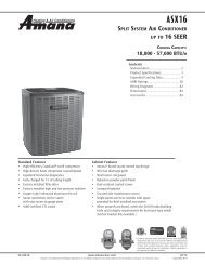
Temperature Rise Range Chart<br />
100<br />
90<br />
80<br />
70<br />
60<br />
50<br />
40<br />
30<br />
20<br />
10<br />
BTU BTU/h OUTPUT Output vs TEMPERATURE Vs. Temperature RISE Rise Chart CHART<br />
600 CFM<br />
700<br />
800<br />
900<br />
1000<br />
1100<br />
1200<br />
1400<br />
1600<br />
1800<br />
2000<br />
2200<br />
2400 CFM<br />
Formulas<br />
FORMULAS<br />
BTU OUTPUT = CFM 1.08 x RISE<br />
BTU/h Output = CFRM x 1.08 x Rise<br />
BTU OUTPUT<br />
RISE = BTU/H Output ÷ CFM<br />
Rise = 1.08 ÷ CFM<br />
CFM x 1.08<br />
30 40 50 60 70 80 90 100 110 120 130 140 150<br />
OUTPUT Output BTU/h BTU/HR x 1,000 x 1000<br />
TEMPERATURE Temperature Rise RISE<br />
SS-D<strong>GMH8</strong> www.amana-hac.com 9
Product Specifications<br />
Wiring Diagram<br />
Wiring is subject to change. Always<br />
refer to the wiring diagram or the<br />
⚠ Warning<br />
unit for the most up-to-date wiring.<br />
High Voltage: Disconnect all power before servicing or installing this unit. Multiple power<br />
sources may be present. Failure to do so may cause property damage, personal injury, or death. ⚡<br />
10 www.amana-hac.com SS-D<strong>GMH8</strong>
Product Specifications<br />
Accessories<br />
Model<br />
Description<br />
<strong>GMH8</strong><br />
0403A*B<br />
<strong>GMH8</strong><br />
0603A*B<br />
<strong>GMH8</strong><br />
0604B*B<br />
<strong>GMH8</strong><br />
0803B*B<br />
<strong>GMH8</strong><br />
0804B*B<br />
<strong>GMH8</strong><br />
0805C*B<br />
<strong>GMH8</strong><br />
1005C*B<br />
<strong>GMH8</strong><br />
1205D*B<br />
LPM-06 LP Conversion Kit (Springs & Orifice)¹ √ √ √ √ √ √ √ √ √<br />
HANG20 High-Altitude Natural Gas Kit (4500+ ft) √ √ √ √ √ √ √ √ √<br />
FTK04 Twinning Kit √ √ √ √ √ √ √ √ √<br />
MVK-01² Masonry Vent Kits √ √ √ √ √ √ √<br />
MVK-02² Masonry Vent Kits √ √<br />
AFE18-60A Fossil Fuel Kit √ √ √ √ √ √ √ √ √<br />
¹ Honeywell or White-Rodgers valves<br />
² Upflow applications only<br />
<strong>GMH8</strong><br />
1405D*B<br />
Model<br />
Description<br />
<strong>GDH8</strong><br />
0403*<br />
<strong>GDH8</strong><br />
0603*<br />
<strong>GDH8</strong><br />
0804*<br />
LPM-06 LP Conversion Kit (Springs & Orifice)¹ √ √ √ √<br />
HANG20 High-Altitude Natural Gas Kit (4500+ ft) √ √ √ √<br />
FTK04 Twinning Kit √ √ √ √<br />
AFE18-60A Fossil Fuel Kit √ √ √ √<br />
SBT 14/17/21* Downflow Sub-base √ √ √ √<br />
¹ Honeywell or White-Rodgers valves<br />
<strong>GDH8</strong><br />
1005*<br />
SS-D<strong>GMH8</strong> www.amana-hac.com 11
Product Specifications<br />
Notes<br />
<strong>Amana</strong>® is a trademark of Maytag Corporation or its related companies and used under license to Goodman Company, L.P. All rights reserved. Our continuing<br />
commitment to quality products may mean a change in specifications without notice. © 2014 • Goodman Company, L.P. • Houston, Texas • Printed in the USA.<br />
12 www.amana-hac.com SS-D<strong>GMH8</strong>