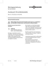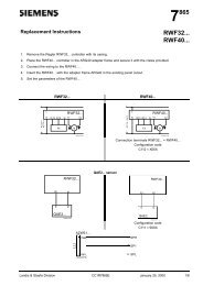
630 Euro Sit Control - Romstal
630 Euro Sit Control - Romstal
630 Euro Sit Control - Romstal

Create successful ePaper yourself
Turn your PDF publications into a flip-book with our unique Google optimized e-Paper software.
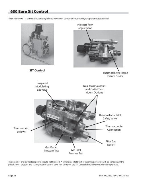
<strong>630</strong> <strong>Euro</strong> <strong>Sit</strong> <strong>Control</strong><br />
<br />
<br />
adjustment<br />
SIT <strong>Control</strong><br />
Snap and<br />
Modulating<br />
gas valve<br />
Dual Main Gas Inlet<br />
<br />
Mount Options<br />
Thermoelectric Flame<br />
Failure Device<br />
Thermoelectic Pilot<br />
Safety Valve<br />
Thermostatic<br />
<br />
Thermocouple<br />
Connection<br />
Gas Outlet<br />
Pressure Test<br />
Gas Inlet<br />
Pressure Test<br />
Pilot Gas<br />
Outlet<br />
<br />
pilot flame is present and stable, but the burner does not come on, the SIT <strong>Control</strong> should be considered inoperative.<br />
Page 38<br />
Part # GCTRM Rev 2 (06/24/09)
<strong>Sit</strong> <strong>Control</strong><br />
Griddle SIT <strong>Control</strong><br />
P/N 4523007<br />
Shorter Thermocouple<br />
No Heat Cover<br />
Temperature <strong>Control</strong><br />
Range 176°F – 600°F<br />
(80°C – 320°C)<br />
Oven SIT <strong>Control</strong>l<br />
P/N Oven – 4523006<br />
59” Thermocouple<br />
Temperature <strong>Control</strong><br />
Range 212°F – 644°F<br />
(100°C – 340°C)<br />
Removal And Replacement<br />
Thermostat Replacement<br />
1. Remove left and middle grates.<br />
2. Remove grate support gas line cover<br />
3. Remove gas line shield<br />
4. Remove Grease crumb tray<br />
<br />
<br />
<br />
and remove.<br />
<br />
assembly.<br />
This control, although very similar to the mechanical controls<br />
found on Garland’s current range and griddle models, has<br />
<br />
advantages to the customer.<br />
It is a safety valve, and thermostat in one assembly, and the<br />
<br />
of the oven burner.<br />
1. The safety valve (should not be removed from the body<br />
of the control for any reason.<br />
2. Familiar Open circuit, closed circuit, and drop out checks<br />
should be made if the internal safety valve is suspected to<br />
be at fault.<br />
<br />
<br />
fixed bypass orifice.<br />
<br />
minor knob adjustments could be appropriate, but it<br />
<br />
5. If a <strong>Sit</strong> control component is suspected to be internally at<br />
fault, replace the control.<br />
<br />
the control cannot control knob set temperature.<br />
8. Push, unlock, and free the thermocouple from the pilot<br />
thermocouple tip holder.<br />
Note: you can remove the oven bottoms for ease of access.<br />
<br />
fittings at the control; be careful not to lose the<br />
thermocouple adapter.<br />
<br />
TO DAMAGE THE THERMOSTATS’ CAPILLARY<br />
Part # GCTRM Rev 2 (06/24/09) Page 39
ut in reverse.<br />
Thermostat Replacement:<br />
Bulb Tip Holder<br />
1. Unmount the oven thermostat capillary from its holder.<br />
2. Carefully snake the capillary through the guide holes and<br />
out of the guard holder.<br />
<strong>Control</strong> capillary guard mounting<br />
Page 40<br />
Part # GCTRM Rev 2 (06/24/09)
to remove the fittings from the valve.<br />
<br />
in place. (Do not lose)<br />
C. Observe capillary and T couple routing<br />
5. Remove the thermostat<br />
To install a new thermostat:<br />
1. Ensure that the fittings removed from the housing are<br />
<br />
the control that is being replaced<br />
2. Reverse the process listed above, ensuring that the<br />
<br />
A. Install left side first before the gas inlet tubing.<br />
B. Observe overlap.<br />
Part # GCTRM Rev 2 (06/24/09) Page 41
D. Insure that the temperature bulb is secured in the<br />
<br />
3. Check for leaks<br />
<br />
your pyrometer as a crosscheck. Temperature recovery<br />
<br />
<br />
this temperature should be no longer than thirty minutes<br />
<br />
NOTE: For complete <strong>Sit</strong> <strong>Control</strong> installation instructions refer<br />
to Garland Service for an installation DVD.<br />
BJWA Gas Thermostat<br />
<br />
<br />
<br />
<br />
<br />
<br />
By-Pass Feature<br />
The BJWA control is a combination of gas cock and by-pass<br />
<br />
by-pass and pilot adjustments. With the BJWA, the gas is<br />
<br />
turn of the dial.<br />
The BJWA can be adapted to have a multiple orientation and<br />
<br />
manifold via a flanged nipple.<br />
Adjustments are on the front for by-pass and temperature<br />
calibration.<br />
The BJWA is typically used on US Range Ovens and griddle<br />
and on Garland griddles.<br />
<br />
<br />
<br />
<br />
must by pass enough gas to keep the entire burner lighted.<br />
To maintain this minimum flame, the by-pass must be set<br />
carefully and accurately. Instructions on setting the by-pass<br />
<br />
1. Light the burner, then turn the dial to “FULL ON”.<br />
<br />
beyond the first mark on the dial.<br />
3. Remove the dial and bezel.<br />
<br />
<br />
until there is a minimum blue stable blue flame over the<br />
entire ported area of the burner.<br />
<br />
until it locks in the “OFF” position.<br />
Page 42<br />
Part # GCTRM Rev 2 (06/24/09)
NOTE<br />
in the closed position.<br />
CALIBRATION<br />
SCREW<br />
BY-PASS<br />
ADJUSTMENT<br />
SCREW<br />
The control should be re-calibrated if your reading<br />
is not within ± 20° F of the dial setting (350°F). If<br />
re-calibration is required, the additional steps that<br />
need to be taken are as follows:<br />
<br />
center of the dial and push the calibration stem. Do Not<br />
turn this stem.<br />
<br />
<br />
<br />
pressure on the calibration stem. Replace the dial inset.<br />
7. Set the dial at 400°F mark. Check the temperature again<br />
as indicated in step 3 and 4 above. If the temperature is<br />
<br />
should be replaced.<br />
If the dial does not have a removable insert or the dial has a<br />
<br />
Calibrating The BJWA Thermostat<br />
This control is a precision component, it is carefully calibrated<br />
at the factory. Re-calibration should not be undertaken until<br />
the by-pass flame has been adjusted and the operating gas<br />
pressure has been confirmed.<br />
<br />
appropriate temperature reading meter. Position of the<br />
instrument/thermocouple should be in the geometric center<br />
of the oven. For a griddle, use a disc type thermocouple<br />
placed in the center of each zone. There should be no<br />
products in the oven or on the griddle<br />
<br />
1. Remove the dial and push out the insert.<br />
2. Replace the dial and turn to the 350° mark.<br />
3. After the burner has been on about 15 minutes, check the<br />
temperature.<br />
4. Continue to check the temperature at 5 minute intervals<br />
<br />
1. Set the dial to the 350°F mark.<br />
2. After the burner has been on about 15 minutes, check the<br />
temperature.<br />
3. Continue to check the temperature at 5 minute intervals<br />
<br />
The control should re-calibrated if your reading<br />
is not within ±20° of the dial setting (350°F). If recalibration<br />
is required, the additional steps that<br />
are need to be taken are as follows:<br />
4. Remove the dial assembly or the complete “D” type stem.<br />
<br />
<br />
<br />
<br />
retainer represents 25°F. Replace the dial assembly or “D”<br />
<br />
6. Set the dial at 400°F mark. Check the temperature again<br />
as indicated in step 3 and 4 above. If the temperature is<br />
<br />
should be replaced.<br />
Part # GCTRM Rev 2 (06/24/09) Page 43
Heavy Duty FDO <strong>Control</strong> Thermostat<br />
<br />
<br />
2. Remove the dial.<br />
<br />
<br />
<br />
stable flame.<br />
The FD <strong>Control</strong> is a heavy duty, high capacity gas thermostat.<br />
It is a modulating snap by-pass.<br />
Garland uses the FD <strong>Control</strong> for range ovens and Pizza decks.<br />
Adjustments are at the front for by-pass and temperature<br />
calibration.<br />
Instructions for Model FDO<br />
Heavy Duty <strong>Control</strong><br />
4. Replace the dial. CAUTION: While making this adjustment,<br />
<br />
<br />
<br />
<br />
check the bypass adjustment as stated.<br />
<br />
<br />
mark.<br />
Dial<br />
Stop<br />
Indicator Mark<br />
B<br />
By-pass Flame<br />
Adjuster<br />
Calibration<br />
Lock<br />
Sc<br />
MODEL<br />
FDO<br />
400<br />
450<br />
500<br />
550<br />
350<br />
Re-calibration<br />
300<br />
Calibration<br />
Plate<br />
250<br />
300<br />
150<br />
Field re-calibration is seldom necessary, and should not<br />
be resorted to unless poor cooking results definitely prove<br />
that the control is not maintaining the temperature to<br />
<br />
re-calibrating use an indicating potentiometer or reliable<br />
mercury oven thermometer.<br />
The model FDO is a precision made instrument, carefully set<br />
at the factory to accurately control oven temperatures, from<br />
150° F (66°C) to 500°F (260°C). All adjustments are accessible<br />
from the front of the appliance after removing the dial. To<br />
remove the dial, grasp the knob portion and pull straight out.<br />
1. Place the thermocouple of the test instrument or<br />
thermometer in the geometric center of the oven.<br />
<br />
<br />
indicator mark for all settings.<br />
<br />
setting” indicator mark.<br />
Page 44<br />
Part # GCTRM Rev 2 (06/24/09)
shaft.<br />
<br />
<br />
control.<br />
7. Turn the calibration plate so that the instrument of the<br />
<br />
<br />
8. Replace the dial.<br />
<br />
<br />
<br />
<br />
designed for them.<br />
If the thermostat is cycling beyond the 20° tolerance and the<br />
re-calibrate the thermostat or<br />
<br />
If the thermostat is out of calibration more than fifty (50)<br />
<br />
suggest that the thermostat be replaced.<br />
UN Type Griddle Thermostat<br />
CALIBRATION<br />
PLATE<br />
CALIBRATION ADJUSTMENT<br />
SCREW<br />
BY-PASS<br />
ADJUSTING SCREW<br />
<br />
and adjust to the “LOWEST POSSIBLE STABLE FLAME<br />
<br />
<br />
the by-pass flame.<br />
6. Replace the dial.<br />
H<br />
L<br />
7. Turn the dial to the “OFF” position.<br />
Re calibration<br />
STEM<br />
CALIBRATION<br />
MARKS<br />
<br />
<br />
1. Be sure that the pilot flames are lit and adjusted.<br />
<br />
to heat for approximately 5 minutes.<br />
<br />
<br />
Do not re-calibrate until the following has been checked:<br />
1. BY-PASS FLAME for proper adjustment (see above).<br />
2 Check that the control bulb is fully inserted into the bulb<br />
tube.<br />
<br />
<br />
thermocouple or a reliable “SURFACE” TYPE thermometer.<br />
<br />
contact.<br />
4. Carefully remove the dial, making sure the setting is not<br />
disturbed.<br />
Part # GCTRM Rev 2 (06/24/09) Page 45
1. Turn all griddle temperature control dials to 350°F<br />
<br />
<br />
taking a test reading.<br />
<br />
<br />
griddle surfaces directly above the sensing bulb of<br />
the control. Reading of the test instrument should be<br />
<br />
<br />
<br />
4. Remove the dial making sure the setting is not disturbed.<br />
<br />
<br />
<br />
<br />
Example – The dial setting is at the 350°F mark. The test<br />
<br />
<br />
6. Replace the dial, turning the dial to the “OFF” position.<br />
7. Repeat steps 1 through 3 to make sure the correct<br />
adjustment has been made.<br />
Electric Thermostat<br />
Thermostat Operation<br />
<br />
<br />
<br />
<br />
<br />
proper action. If the thermostat is out of calibration more<br />
<br />
We suggest that the thermostat be replaced.<br />
Dial Shaft<br />
<br />
Calibration<br />
Scr<br />
1/4" Turn<br />
Thermostat calibration<br />
Oven thermostat<br />
Increase<br />
Decrease<br />
1 Place the thermocouple of the test instrument in the<br />
center of the oven.<br />
2. Turn the oven temperature control dial to 400°F. In order<br />
<br />
<br />
test reading.<br />
<br />
cycles “OFF” as indicated by the cycling pilot lamp. If the<br />
<br />
<br />
Page 46<br />
Part # GCTRM Rev 2 (06/24/09)
4. Carefully remove the thermostat dial, not disturbing the<br />
dial setting.<br />
<br />
<br />
<br />
<br />
<br />
approximately 25°F.<br />
6. Replace the thermostat dial and repeat steps 1 through 3<br />
to verify that the correct adjustment has been made.<br />
Griddle thermostat<br />
<br />
or a reliable surface type pyrometer. Note: a drop of oil on<br />
<br />
plate.<br />
<br />
griddle temperature to stabilize, the thermostats must be<br />
<br />
<br />
cycles “OFF” by placing the thermocouple firmly on the<br />
griddle surface directly above the sensing bulb of the<br />
<br />
315°F. If the reading is outside of these limits, calibrate as<br />
<br />
4. Carefully remove the thermostat dial, not disturbing the<br />
dial setting.<br />
<br />
<br />
<br />
<br />
<br />
approximately 25°F.<br />
6. Replace the thermostat dial and repeat steps 1 though 3<br />
to verify that the correct adjustment has been made.<br />
Part # GCTRM Rev 2 (06/24/09) Page 47