Acadia Amalgam Separator - Operators Manual - Air Techniques, Inc.
Acadia Amalgam Separator - Operators Manual - Air Techniques, Inc.
Acadia Amalgam Separator - Operators Manual - Air Techniques, Inc.

Create successful ePaper yourself
Turn your PDF publications into a flip-book with our unique Google optimized e-Paper software.
#3 ORN<br />
#4 BRN<br />
#2 YEL<br />
#3 ORN<br />
#2 YEL<br />
RED<br />
BRN<br />
#3 ORN<br />
#2 YEL<br />
#4 BRN<br />
#3 ORN<br />
#2 YEL<br />
BLK<br />
BLK<br />
BLK<br />
BLK<br />
RED<br />
BRN<br />
RED<br />
#3 ORN<br />
BRN<br />
#2 YEL<br />
#4 BRN<br />
#3 ORN<br />
#2 YEL<br />
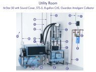
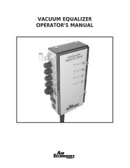
ACADIA Model with Alert Monitor<br />
Gather connected wires<br />
together in a loose "S" and<br />
secure with the strain relief.<br />
To <strong>Acadia</strong> <strong>Amalgam</strong><br />
<strong>Separator</strong> Liquid Level<br />
Sensor Connector Jack<br />
Important:<br />
Always connect one end of the<br />
Liquid Level Sensor Cable to the<br />
Float Switch Connector J4 before<br />
installing the module onto the<br />
<strong>Acadia</strong> <strong>Amalgam</strong> <strong>Separator</strong>.<br />
Figure 16. Typical Wire Routing Through Strain Reliefs<br />
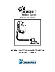
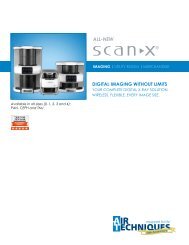
1 24 PW IN<br />
J1<br />
1 VAC RMT 1 LED SEL 1 EQ SW 1<br />
J3<br />
J8<br />
J7<br />
J5<br />
J2<br />
EQ SW TB<br />
Connectors J7 & J5 Not<br />
Used<br />
Connector J3<br />
Not Used<br />
Connectors J7 & J5<br />
Not Used<br />
To Primary Pump 24VAC Low<br />
Voltage Electrical Box (See Note 1)<br />
To Optional Bi-Color<br />
Panel Switch<br />
To 12 VDC Power Supply<br />
(See Note 1)<br />
To Optional Bi-Color Panel Switch for<br />
indicator function only.<br />
Tie YEL & ORN switch leads together.<br />
View A. Connections Using 24 VAC Power, No Vacuum Equalizer and<br />
Optional Panel Switch<br />
View B. Connections Using 12 VDC Power, No Vacuum Equalizer and<br />
Optional Panel Switch<br />
1 24 PW IN 1 VAC RMT 1 LED SEL 1 EQ SW 1<br />
J1 J3 J8 J7<br />
J5<br />
J2<br />
EQ SW TB<br />
1 24 PW IN 1 VAC RMT 1 LED SEL 1 EQ SW 1<br />
J1 J3 J8 J7<br />
J5<br />
J2<br />
EQ SW TB<br />
To Primary Pump<br />
24VAC Low Voltage<br />
Electrical Box<br />
(See Note 1)<br />
To Vacuum Equalizer Pump 1<br />
Terminal Block. (See Notes 2 & 3)<br />
To Bi-Color Panel Switch<br />
for Vacuum Equalizer<br />
(See Note 2)<br />
To Vacuum Equalizer Control<br />
Panel Switch Terminal Block<br />
(See Notes 2 & 3)<br />
To 12 VDC Power<br />
Supply (See Note 1)<br />
Connector<br />
J3 Not Used<br />
(See Note 4)<br />
To Bi-Color<br />
Panel Switch for<br />
Vacuum Equalizer<br />
(See Note 2)<br />
To Vacuum Equalizer<br />
Control Panel Switch<br />
Terminal Block<br />
(See Notes 2 & 3)<br />
View C. Connections Using 24 VAC Power, a Vacuum Equalizer<br />
and Remote Panel Switch<br />
View D. Connections Using 12 VDC Power, a Vacuum Equalizer<br />
and Remote Panel Switch<br />
Notes:<br />
1. The Primary Pump must have its power circuit breakers left in the ON position to supply 24VAC low voltage power.<br />
When an optional (P/N A5135) 12 volt DC power supply is used to power the <strong>Acadia</strong> Alert Monitor Module, clip off the plug end and connect the supply<br />
wires to the #4 BRN and #2 YEL leads of connector J1. This connection is polarity insensitive.<br />
2. The Vacuum Equalizer is optional equipment and purchased separately. The Vacuum Equalizer automatically regulates the facility vacuum level.<br />
3. This connection re-routes primary pump control to the Vacuum Equalizer pump terminal block when the optional Vacuum Equalizer is installed.<br />
4. All Pump connections are wired directly to Vacuum Equalizer in 12 VDC power configurations.<br />
Figure 17. <strong>Acadia</strong> Alert Monitor Module Electrical Connection Configurations<br />
16