Acadia Amalgam Separator - Operators Manual - Air Techniques, Inc.
Acadia Amalgam Separator - Operators Manual - Air Techniques, Inc.
Acadia Amalgam Separator - Operators Manual - Air Techniques, Inc.

You also want an ePaper? Increase the reach of your titles
YUMPU automatically turns print PDFs into web optimized ePapers that Google loves.
Part Numbers: A1250 and A1350<br />
INSTRUCTION MANUAL
TABLE OF CONTENTS<br />
Section<br />
Page<br />
Introduction .......................................................................... 3<br />
Safety Notice. ........................................................................ 4<br />
Specifications ........................................................................ 5<br />
Unpacking and Inspection. .............................................................. 6<br />
Installation Information ................................................................. 7<br />
Filter Replacement and Disposal ......................................................... 12<br />
Spare Replacement Parts. .............................................................. 13<br />
<strong>Acadia</strong> Model with Alert Monitor ......................................................... 14<br />
Maintenance ......................................................................... 18<br />
Troubleshooting. ...................................................................... 18<br />
Warranty ............................................................................ 18<br />
On-Line Warranty Registration ........................................................... 18<br />
If You Need Assistance ................................................................. 18<br />
LIST OF ILLUSTRATIONS<br />
Figure Title Page<br />
1 <strong>Acadia</strong> <strong>Amalgam</strong> <strong>Separator</strong> Assembly, PN A1250 ................................ 3<br />
2 <strong>Acadia</strong> <strong>Amalgam</strong> <strong>Separator</strong> Assembly Outline/Dimension Drawing ................... 5<br />
3 <strong>Acadia</strong> <strong>Amalgam</strong> <strong>Separator</strong> Assembly Component Identification .................... 6<br />
4 Typical <strong>Acadia</strong> <strong>Amalgam</strong> <strong>Separator</strong> Installation Configurations . . . . . . . . . . . . . . . . . . . . . . .7<br />
5 Changing the <strong>Acadia</strong> <strong>Amalgam</strong> <strong>Separator</strong> Input to Right-side Orientation. ............. 7<br />
6 <strong>Separator</strong> Wall Mounting .................................................... 8<br />
7 <strong>Separator</strong> Inlet and Outlet Connection Fittings Install Locations. ..................... 8<br />
8 Solid Collection Filter Installation ............................................. 8<br />
9 Typical <strong>Acadia</strong> <strong>Amalgam</strong> <strong>Separator</strong> Installation Configurations . . . . . . . . . . . . . . . . . . . . . . .9<br />
10 <strong>Acadia</strong> <strong>Amalgam</strong> <strong>Separator</strong> Connection to the Treatment Operatory Output Piping . . . . . . .9<br />
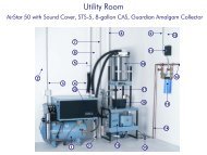
11 <strong>Acadia</strong> <strong>Amalgam</strong> <strong>Separator</strong> Connection to a STS Pump/CAS Tank Vacuum System<br />
(Direct connection to Separation Tank.) ........................................10<br />
12 <strong>Acadia</strong> <strong>Amalgam</strong> <strong>Separator</strong> Connection to a VacStar System<br />
(Direct pump connection. No Separation Tank.). .................................11<br />
13. <strong>Acadia</strong> <strong>Amalgam</strong> <strong>Separator</strong> Assembly, PN A1350, Alert Monitor Module<br />
Front Panel View ..........................................................14<br />
14. <strong>Acadia</strong> Alert Monitor Module Accessory Kit, P/N A1378 ...........................14<br />
15. <strong>Acadia</strong> Alert Monitor Panel Electronics Enclosure ...............................15<br />
16. Typical Wire Routing Through Strain Reliefs .....................................16<br />
17. <strong>Acadia</strong> Alert Monitor Module Electrical Connection Configurations ..................16<br />
18. <strong>Acadia</strong> Alert Monitor Panel Assembly Installation and<br />
Liquid Level Sensor Cable Connection .........................................17<br />
19. <strong>Acadia</strong> <strong>Amalgam</strong> <strong>Separator</strong> with <strong>Acadia</strong> Alert Monitor Module, PN A1350 ............17<br />
2
INTRODUCTION<br />
This manual covers the installation and maintenance of the <strong>Acadia</strong> <strong>Amalgam</strong> <strong>Separator</strong> Assemblies PN A1250 and<br />
A1350. Although both units provide the same high level solid collection function, the <strong>Acadia</strong> PN A1350, also incorporates<br />
an <strong>Acadia</strong> Alert Monitor Module. This addition feature monitors the Solid Collection Filter and provides a visual<br />
and audible indication when the filter needs replacement.<br />
Installation tacks include the following:<br />
Adding to any existing liquid ring or dry vacuum system.<br />
Installing as part of a new liquid ring or dry vacuum system.<br />
The manual provides additional maintenance and troubleshooting information for each unit, as well as, instructions<br />
to replace a filled Disposable Solid Collection Filter. The <strong>Acadia</strong> <strong>Amalgam</strong> <strong>Separator</strong> is hereafter referred to as the<br />
<strong>Separator</strong> in this manual. Make sure to review and follow the information specific to your installation to ensure that<br />
the <strong>Separator</strong> provides the highest level of safe service.<br />
Important: Each kit provides the necessary parts to connect to both a STS Pump with CAS Tank and VacStar vacuum systems<br />
manufactured By <strong>Air</strong> <strong>Techniques</strong>. If the existing installations need different size fittings or hose lengths, they must be<br />
provided by the installer.<br />
As shown by Figure 1, both <strong>Separator</strong> models are designed to exceed ISO 11143 requirements in the removal of<br />
amalgam from a dental suction system's wastewater stream. Installed between dental operatories and vacuum<br />
pumps, the <strong>Separator</strong> uses a disposable filter comprised of a sedimentation labyrinth containing articulated foam<br />
filters and a granular filter media. Each unit is designed to provide continuous cyclonic separation action of liquids<br />
and solids from gases causing a sedimentation process where high-density particles (<strong>Amalgam</strong>) fall from suspension<br />
in the wastewater stream and become trapped within the filters. The unit has been independently tested and<br />
certified to ISO 11143.<br />
Features include:<br />
Capable of processing effluent for up to ten (10) operatories.<br />
Exceeds the ISO 11143 standard for separation efficiency.<br />
Continuous cyclonic separation of liquids and solids from gases.<br />
Reusable large particle inlet filter strainer.<br />
Minimal maintenance required.<br />
Disposable Collection Filter.<br />
• Easily removed using a quarter turn and pull.<br />
• Transparent housing enables user monitoring of capacity and when to replace filter.<br />
• Closure Cap provided to seal Disposable Collection Filter for transport.<br />
Mounting & Connections<br />
• Multiple mounting configurations (Wall Mount / Floor Mount).<br />
• Quick and easy installation using included tubing and plumbing fittings.<br />
• Custom molded clips allow easy assembly and disassembly of connection components.<br />
• Multiple inlet connection orientations that accommodates standard 1½ inch diameter pipe using a nohub<br />
coupling or provided 1½ ID inch hose.<br />
LARGE PARTICLE<br />
INLET FILTER<br />
STRAINER<br />
Note: Part Number A1250 is shown. Part<br />
Number A1350, an <strong>Acadia</strong> model<br />
with the Alert Monitor Module is<br />
also available. See page 14.<br />
INPUT CONNECTOR<br />
FROM OPERATORIES<br />
AMALGAM SEPARATOR<br />
CHASSIS/MOUNTING<br />
BRACKET P/N A1297<br />
OUTPUT CONNECTOR<br />
TO VACUUM SYSTEM<br />
Direct to Liquid Pump<br />
or<br />
Direct to Separation Tank<br />
of a Dry Pump System<br />
DISPOSABLE SOLID<br />
COLLECTION FILTER<br />
Figure 1. <strong>Acadia</strong> <strong>Amalgam</strong> <strong>Separator</strong> Assembly<br />
3
SAFETY NOTICE<br />
Knowledge of General Safety<br />
The <strong>Separator</strong> has been designed to minimize exposure of personnel to hazards. While the equipment is designed<br />
for safe operation, certain precautions must be observed. Use of the <strong>Separator</strong> not in conformance with the<br />
instructions specified in this manual may result in permanent failure of the unit.<br />
Users must exercise every precaution to ensure personnel safety, and be familiar with the general safety procedures<br />
concerning the <strong>Separator</strong> and associated vacuum systems, which include the following.<br />
Observe all local codes and relevant regulations when installing the <strong>Separator</strong>.<br />
Converting or modifying the <strong>Separator</strong> in any way is strictly prohibited. In such cases, any and all warranties will<br />
immediately become invalid.<br />
The operator must be knowledgeable in the operation of the appliance.<br />
The product is not designed to be used in medical treatment areas where there exists the danger of explosion.<br />
Areas where explosions could occur are those where flammable anesthetic material, skin cleansers, oxygen and<br />
skin disinfectants are present. This appliance is not to be used in areas where the atmosphere could cause fire.<br />
Authorized Dealer Service Only.<br />
The <strong>Separator</strong> is intended to be installed and serviced only by an authorized dealer service technician. Failure to heed<br />
this warning may result in equipment damage or personal injury, and will void any and all warranties. Contact your<br />
authorized dealer for service information.<br />
Dental Waste Handling<br />
Solid Collection Filters collect waste materials from dental procedures. All maintenance personnel must be familiar<br />
with the procedures and practices for handling such dental waste and exercise every precaution to ensure personnel<br />
safety. Additionally personnel must follow all local, state and/or federal laws and regulations for the proper disposal of<br />
dental waste containing mercury. Any operation, procedure or practice, which, if not strictly observed, may result<br />
in injury or long-term health hazards to personnel and should be handled, stored and disposed of according to<br />
regulations applying to dental waste containing mercury.<br />
Correct Usage<br />
The <strong>Separator</strong> is for Dental Use only. Any use of the <strong>Separator</strong> that is not described in this Instruction <strong>Manual</strong> is<br />
deemed to be incorrect usage.<br />
<strong>Inc</strong>orrect Usage<br />
Any use of the <strong>Separator</strong> above and beyond that laid down in this Instruction <strong>Manual</strong> is deemed to be incorrect usage.<br />
The manufacturer cannot be held liable for any damage resulting from incorrect usage. The operator will be held liable<br />
and bears all risks.<br />
4
Number of dental units serviced Up to 10<br />
Maximum Liquid flow rate<br />
Liquid surge capacity<br />
Solids collection capacity<br />
Separation efficiency<br />
Maximum Vacuum<br />
Inlet Filter Screen Size<br />
1 liter per minute (0.26 gal per minute)<br />
3 liters (0.79 gal)<br />
1 liter (0.26 gal)<br />
Exceeds ISO 11143 requirements<br />
50.80 cm/Hg (20 in/Hg)<br />
6 mm (0.24 in)<br />
Classification Type 3 per ISO 11143<br />
Connection type<br />
Mounting<br />
Weight (empty)<br />
3.81 cm (1½ in) Hose barb adaptor with retaining clip<br />
Attached chassis/mounting bracket provided<br />
9.5 kg (21 lbs)<br />
SPECIFICATIONS<br />
Dimensions Width Depth Height<br />
53 cm 38 cm 69 cm<br />
(21 in) (15 in) (27 in)<br />
37.4 cm<br />
(15 in)<br />
52.3 cm<br />
(21 in)<br />
68.3 cm<br />
(27 in)<br />
Figure 2. <strong>Acadia</strong> <strong>Amalgam</strong> <strong>Separator</strong> Assembly Outline/Dimension Drawing<br />
5
UNPACKING AND INSPECTION<br />
Unpacking<br />
As shown by Figure 3, the <strong>Separator</strong> is shipped in a single carton containing the <strong>Separator</strong> assembly secured to the<br />
Chassis/Mounting Bracket, the Solid Collection Filter, inlet and outlet connection fittings and an installation accessory<br />
kit. Unpack each component of the <strong>Separator</strong> and inspect for physical damage such as scratched panels, damaged<br />
connectors, etc.<br />
<strong>Inc</strong>luded <strong>Separator</strong> Components<br />
Each <strong>Separator</strong> consists of the components shown by Figure 3. Verify that all listed items were received. If any item is<br />
missing, notify <strong>Air</strong> <strong>Techniques</strong>.<br />
<strong>Amalgam</strong><br />
<strong>Separator</strong><br />
Assembly<br />
P/N A1210<br />
90 o Non Rotating<br />
Elbow with O-ring<br />
Spacer & Screw<br />
P/N A1381<br />
90 o Elbow with O-ring<br />
P/N A1384<br />
1½ <strong>Inc</strong>h Hose Barb<br />
Adaptor (Qty 2)<br />
P/N A1223<br />
Inlet Filter Housing<br />
P/N A1282<br />
and<br />
Large Particle Inlet<br />
Filter Strainer<br />
P/N A1283<br />
Retaining Clip<br />
(Qty 5)<br />
P/N A1237<br />
<strong>Amalgam</strong> <strong>Separator</strong><br />
Chassis/Mounting<br />
Bracket P/N A1297<br />
Wall Mounting Kit,<br />
P/N A1420.<br />
See table below.<br />
Solid Collection Filter<br />
P/N A1280<br />
Installation Accessory<br />
Kit, P/N A1359.<br />
See table below.<br />
Foot Installation Kit,<br />
P/N A1399.<br />
See table below.<br />
<strong>Acadia</strong> Alert Monitor<br />
Module Accessory Kit,<br />
P/N A1378.<br />
See page 14.<br />
Figure 3. <strong>Acadia</strong> <strong>Amalgam</strong> <strong>Separator</strong> Assembly Component Identification<br />
Important: Installation Accessory Kit, P/N A1359 provides the necessary parts to connect to both a STS Pump with CAS Tank and<br />
VacStar vacuum systems manufactured by <strong>Air</strong> <strong>Techniques</strong>. If the existing installations need different size fittings or<br />
hose lengths, they must be provided by the installer.<br />
Installation Kit Components<br />
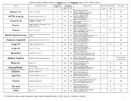
The table below lists the supplied parts used to connect the <strong>Separator</strong> to new or existing vacuum systems.<br />
Installation Kits<br />
Description Part No. Quantity<br />
Installation Accessory Kit A1359 1<br />
1½ inch ID Clear with White Spiral Hose<br />
Note: If more than 6 feet of hose is needed, order additional P/N 54521 by the foot.<br />
54521 6 Feet<br />
1½ inch MNPT X 1-1/2 inch BARB Connector Adapter 57253S 1<br />
1½ inch SLIP X 1-1/2 inch FNPT PVC Connector Adapter 54234 1<br />
1.31 - 2.25 inch Diameter Hose Clamp 57169 4<br />
1½ inch SPG X 3/4 inch FNPT Reducing Bushing A1164 1<br />
1½ inch SPG X 1 inch FNPT, Reducing Bushing 55552 1<br />
1½ inch Connector Flexible Coupling (No Hub) 57238 2<br />
Foot Installation Kit A1399 1<br />
Foot; Non Skid,.5 + .1/-0 HIGH X 1"Diameter, #8 screw 61173 4<br />
Screw; 8-32 X 5/8, Phillips Pan Head, 18-8 S.S. 30463 4<br />
#8, Flat Washer,18-8 SS 30052 4<br />
8-32, Hex Nut, KEP, SS 31577 4<br />
Wall Mounting Kit A1420 1<br />
#10 X 1 inch, Anchor, Plastic 30936 4<br />
#12 X 3/4 Type A, Phillips Pan Head, 30935 4<br />
#10, Flat Washer,18-8 SS 30024 4<br />
6
INSTALLATION INFORMATION<br />
Important: The <strong>Separator</strong> is only installed between the treatment operatory and the vacuum system input. DO NOT connect the unit<br />
to the outlet of any separation tank (dry vacuum system) or liquid ring pump (wet vacuum system).<br />
Introduction<br />
As shown by Figure 4, a <strong>Separator</strong> is installed onto either an existing or new dry pump or liquid ring pump vacuum<br />
system. The unit is only installed between the treatment operatory output and the vacuum system input. This new<br />
installation or modification is to be performed by authorized service personnel using similar quality connection hoses<br />
and fittings. All installations must conform to local codes and meet all local, state and/or federal environmental laws<br />
and regulations.<br />
ACADIA <strong>Separator</strong><br />
Input Connection<br />
Any<br />
Water Ring Pump<br />
Treatment<br />
Operatory<br />
OR<br />
ACADIA <strong>Separator</strong><br />
Output Connection<br />
<strong>Air</strong>/Water<br />
Separation<br />
Tank<br />
AND<br />
Any Dry<br />
Vacuum<br />
Pump<br />
Figure 4. Typical <strong>Acadia</strong> <strong>Amalgam</strong> <strong>Separator</strong> Installation Configurations<br />
Important: Refer to pages 14 thru 18 when installing an <strong>Acadia</strong> with an <strong>Acadia</strong> Alert Monitor Module, PN A1350.<br />
Input/Output Connector Orientation Option<br />
Although the <strong>Amalgam</strong> <strong>Separator</strong> is shipped with the input connector facing to the left-side, the design allows the entire<br />
separator assembly to be rotated 180 degrees so the input connector can face to the right side to meet installation<br />
requirements. Refer to Figure 5 and perform the following steps to change the connector orientation as necessary.<br />
Note: Make sure to save all removed screws. They are reused during installation.<br />
1. Remove the 4 screws securing the cover plate to the front enclosure of the separator and remove the plate.<br />
2. Remove the 4 screws securing the separator assembly to the chassis/mounting bracket.<br />
3. Rotate the separator assembly 180 degrees and remount onto the chassis/mounting bracket and secure with the<br />
4 screws removed in step 2.<br />
4. Install the cover plate to the front enclosure of the separator and secure with the 4 screws removed in step 1.<br />
Left-side Input Connection<br />
(See Note 1)<br />
<strong>Amalgam</strong><br />
<strong>Separator</strong><br />
Assembly<br />
P/N A1210<br />
Right-side<br />
Input Connection<br />
<strong>Amalgam</strong> <strong>Separator</strong><br />
Assembly P/N A1210<br />
Cover Plate<br />
<strong>Amalgam</strong> <strong>Separator</strong><br />
Chassis/Mounting<br />
Bracket P/N A1297<br />
Plate Cover<br />
(See Note 2)<br />
Right-side<br />
Output Connection<br />
Notes:<br />
Removing the <strong>Separator</strong> Assembly from<br />
the Chassis/Mounting Bracket<br />
1. The unit is shipped with the separator assembly secured to the chassis/mounting bracket with the input on the left-side.<br />
2. Install and connect the <strong>Amalgam</strong> Monitor Module as necessary.<br />
Figure 5. Changing the <strong>Acadia</strong> <strong>Amalgam</strong> <strong>Separator</strong> Input to Right-side Orientation<br />
7<br />
Left-side<br />
Output Connection<br />
Installing the <strong>Separator</strong> Assembly to the Chassis/<br />
Mounting Bracket Right-side Input Connection
INSTALLATION PROCEDURE<br />
<strong>Acadia</strong> <strong>Amalgam</strong> <strong>Separator</strong> Installation.<br />
Install the <strong>Acadia</strong> <strong>Amalgam</strong> <strong>Separator</strong> onto either an existing or<br />
new dry pump (STS Pump/CAS Tank) or liquid pump (VacStar)<br />
vacuum system by performing the procedures provided by the<br />
following paragraphs.<br />
<strong>Acadia</strong> <strong>Amalgam</strong> <strong>Separator</strong> Mounting.<br />
The <strong>Acadia</strong> <strong>Amalgam</strong> <strong>Separator</strong> can be placed on the floor or<br />
hung on a wall. In either installation the <strong>Separator</strong> must be level,<br />
securely mounted and located between the output of the facility<br />
Treatment Operatory and the vacuum system input.<br />
Refer to Figure 6 and mount the <strong>Separator</strong> assembly as shipped<br />
(secured to the Chassis/Mounting Bracket) to an existing wall<br />
using lag bolts. The structure and bolts should be capable of<br />
supporting 25 pounds. Mount directly using the four pre-drilled<br />
Keyhole Mounting Holes in the Chassis/Mounting Bracket.<br />
Molly bolts may be used providing they and the wall are capable<br />
of supporting the load.<br />
Keyhole<br />
Mounting<br />
Hole<br />
Keyhole<br />
Mounting<br />
Hole<br />
Keyhole<br />
Mounting<br />
Hole<br />
Keyhole<br />
Mounting<br />
Hole<br />
Figure 6. <strong>Separator</strong> Wall Mounting<br />
Inlet and Outlet Connection Fittings Installation.<br />
Refer to Figure 7 and install the Inlet and Outlet Connection Fittings as necessary. Each part slips over the associated<br />
connection point and is secured by an individual retaining clip. The Large Particle Inlet Filter Strainer can be<br />
installed using all or none of the provided elbows as necessary to meet the installation space requirements.<br />
90 o Non Rotating<br />
Elbow with O-ring<br />
Spacer & Screw<br />
Retaining Clip<br />
Inlet Filter<br />
Housing<br />
Inlet Filter<br />
Strainer<br />
Note:<br />
90 o Elbow<br />
& Retaining<br />
Clip<br />
Barb Adaptor &<br />
Retaining Clip<br />
The Large Particle Inlet Filter can be installed using<br />
the provided elbows as necessary to meet the<br />
requirements of individual installations.<br />
Barb Adaptor &<br />
Retaining Clip<br />
Figure 7. <strong>Separator</strong> Inlet and Outlet Connection Fittings Install Locations<br />
Solid Collection Filter Installation.<br />
Refer to Figure 8 and install the Solid Collection Filter as<br />
follows.<br />
1. Remove the cover from the filter and save for future filter<br />
replacements.<br />
2. Align the two tabs of the filter with the corresponding slots<br />
of the collar.<br />
3. Lift the Solid Collection Filter into place and secure by<br />
turning to the left.<br />
4. Record the installation date<br />
on the label.<br />
Melville, NY 11747 USA<br />
DATE INSTALLED:<br />
REPLACE FILTER WITHIN 12 MONTHS<br />
FULL<br />
REPLACE FILTER<br />
USE WITH AMALGAM SEPARATOR A1250<br />
MAX FLOW RATE: 1 LITER / MINUTE<br />
PN A1361<br />
Figure 8. Solid Collection Filter Installation<br />
8
INSTALLATION PROCEDURE<br />
Standard <strong>Separator</strong>.<br />
Figure 9, shows standard <strong>Separator</strong> installations as part of a new or in an existing STS Pump/CAS Tank (dry pump)<br />
or VacStar (liquid pump) vacuum system manufactured by <strong>Air</strong> <strong>Techniques</strong><br />
ACADIA SEPARATOR<br />
ASSEMBLY<br />
FROM<br />
OPERATORY<br />
LIQUIDS/GAS<br />
SOLIDS<br />
ACADIA <strong>Separator</strong><br />
Input Connection<br />
from Operatory.<br />
See Figure 8<br />
GAS/<br />
LIQUIDS<br />
CAS<br />
SEPARATION<br />
TANK<br />
ACADIA <strong>Separator</strong><br />
Output Connection to<br />
Input of CAS Tank.<br />
See Figure 9<br />
LIQUIDS, GAS &<br />
SOLIDS FROM<br />
OPERATORY<br />
ACADIA <strong>Separator</strong> Input<br />
Connection from Operatory.<br />
See Figure 8<br />
GAS &<br />
LIQUIDS<br />
ACADIA <strong>Separator</strong><br />
Output Connection to<br />
Input Filter of Pump.<br />
See Figure 10<br />
WATER SUPPLY<br />
INTO PUMP<br />
LIQUID<br />
RING<br />
PUMP<br />
DRY STS<br />
VACUUM<br />
PUMP<br />
ACADIA AMALGAM<br />
SEPARATOR<br />
ASSEMBLY<br />
INPUT<br />
FILTER<br />
GAS & LIQUIDS<br />
FLOOR DRAIN<br />
Single Pump System Shown using an <strong>Air</strong> <strong>Techniques</strong> CAS<br />
Separation Tank. Dual Pump Systems are Connected the Same.<br />
Single Pump System without a Separation Tank Shown.<br />
Dual Pump Systems are Connected the Same.<br />
Figure 9. Typical <strong>Acadia</strong> <strong>Amalgam</strong> <strong>Separator</strong> Installation Configurations<br />
<strong>Separator</strong> Connection to the Treatment Operatory Output.<br />
Typical VacStar and STS/CAS installations use 1-1/2 inch PVC piping for the output from the facility Treatment<br />
Operatory. Refer to Figure 10 and connect <strong>Separator</strong> to the operatory piping as follows.<br />
1. Install the 1½ inch SLIP X 1-1/2 inch FNPT connector adapter to the operatory output piping.<br />
2. Install the 1½ inch MNPT X 1-1/2 inch BARB connector adapter and tighten.<br />
3. Measure the distance between the BARB connector adapters of the operatory outlet and the <strong>Separator</strong> input. Cut<br />
the required length from the supplied 1-1/2 inch hose. Install the hose between the fittings and secure with 1-1/2<br />
inch Hose Clamps.<br />
1-1/2" Barb Adaptor<br />
Input from<br />
ACADIA <strong>Separator</strong><br />
ACADIA<br />
<strong>Separator</strong> Input Port<br />
See Figure 6<br />
Adapter 1-1/2" Slip<br />
X 1-1/2" FNPT<br />
1-1/2" Hose<br />
Clamps<br />
1-1/2" Piping from<br />
Treatment Operatory<br />
Adapter 1-1/2" NPT<br />
X 1-1/2" Barb<br />
ACADIA<br />
SEPARATOR<br />
1-1/2"<br />
Hose<br />
ACADIA<br />
<strong>Separator</strong> Output Port<br />
to Vacuum System Input<br />
See Figures 10 & 11<br />
Figure 10. <strong>Acadia</strong> <strong>Amalgam</strong> <strong>Separator</strong> Connection to the Treatment Operatory Output Piping<br />
9
INSTALLATION PROCEDURE<br />
Important: The 1-1/2 inch hose used to connect the <strong>Separator</strong> to the input suction line of the CAS Tank is supplied in the CAS Tank<br />
Accessory Pack, P/N 54135, included with each new CAS Tank.<br />
Installation Accessory Kit, P/N A1359 (see page 6), provides the necessary parts to connect to separation tank<br />
installations manufactured by <strong>Air</strong> <strong>Techniques</strong>. Installation to systems made by other manufacturers may need different<br />
size hoses and/or fittings that must be provided by the installer.<br />
<strong>Separator</strong> Connection to CAS Separation Tank.<br />
The input suction line connection to the CAS separation tank of STS/CAS installations uses 1-1/2 inch hose, which is<br />
included in the CAS Tank Accessory Pack, P/N 54135, supplied with each CAS tank. Refer to Figure 11 and connect<br />
the <strong>Separator</strong> to a CAS Tank by performing the following for either a new or existing installation.<br />
Warning: The following procedures should be performed while wearing skin and eye protection.<br />
Any area where material from the tank has spilled, should be thoroughly disinfected.<br />
New STS/CAS installations -<br />
1. Measure the distance between the CAS Tank inlet and the <strong>Separator</strong> output BARB connector adapters.<br />
2. Cut the required length from the 1-1/2 inch hose supplied in the CAS Tank Accessory Pack.<br />
3. Install the hose between the fittings and secure with 1-1/2 inch hose clamps.<br />
Existing STS/CAS installations -<br />
1. Disconnect the operatory output end of the existing hose connected from the CAS Tank inlet.<br />
2. Leaving the hose connected to the CAS Tank inlet, transfer the operatory output end of the hose to the output<br />
BARB connector adapter of the <strong>Separator</strong>.<br />
3. Cut any surplus length from the hose as necessary.<br />
4. Secure the hose to the <strong>Separator</strong> output BARB connector adapter with a 1-1/2 inch hose clamp.<br />
1-1/2" Barb Adaptor<br />
Output from<br />
ACADIA<br />
<strong>Separator</strong><br />
1-1/2" Hose<br />
Clamp<br />
1-1/2 inch Hose<br />
Tank Input Port<br />
Adapter 1-1/2" NPT<br />
X 1-1/2" Barb<br />
CAS<br />
SEPARATION<br />
TANK<br />
To<br />
STS Vacuum<br />
Pump<br />
Figure 11. <strong>Acadia</strong> <strong>Amalgam</strong> <strong>Separator</strong> Connection to a STS Pump/CAS Tank Vacuum System<br />
(Direct connection to Separation Tank.)<br />
10
INSTALLATION PROCEDURE<br />
Important: Dual pump VacStar installations use 1 inch hose & fittings, while single pump installations use 3/4 inch hose & fittings.<br />
Installation Accessory Kit, P/N A1359 (see page 6), provides the necessary parts to connect to liquid pump installations<br />
manufactured by <strong>Air</strong> <strong>Techniques</strong>. Installation to systems made by other manufacturers may need different size hoses<br />
and/or fittings that must be provided by the installer.<br />
<strong>Separator</strong> Connection to VacStar Systems.<br />
The input suction line connection to VacStar installations uses 1-1/2 inch hose, which is included in the Installation<br />
Accessory Pack, P/N 54135, supplied with each VacStar pump. Refer to Figure 12 and connect the <strong>Separator</strong> to a<br />
VacStar by performing the following for either a new or existing installation.<br />
Warning: The following procedures should be performed while wearing skin and eye protection.<br />
Any area where material from the tank has spilled, should be thoroughly disinfected.<br />
New VacStar installations -<br />
1. Measure the distance between the VacStar inlet filter and the <strong>Separator</strong> output BARB connector adapters.<br />
2. Cut the required length from the supplied appropriate diameter hose; 3/4 inch for a single pump VacStar system<br />
or 1 inch for a dual pump system.<br />
3. Install the hose between the fittings and secure with 1-1/2 inch hose clamps.<br />
Existing VacStar installations -<br />
1. Disconnect the operatory output end of the existing hose connected from the inlet filter of the VacStar.<br />
2. Leaving the hose connected to the VacStar inlet filter, transfer the operatory output end of the hose to the output<br />
BARB connector adapter of the <strong>Separator</strong>.<br />
3. Check the hose length. If too long, remove the MNPT fitting from the hose and cut any surplus length as<br />
necessary.<br />
4. Reinstall the MNPT fitting (removed above) into the hose and install the appropriate reducing bushing; either an<br />
1½ inch SPG X 3/4 inch FNPT bushing for a single pump VacStar or an 1½ inch SPG X 1 inch FNPT bushing<br />
for dual pump systems.<br />
5. Install a 1½ inch connector flexible coupling (No Hub) onto the slip side of the reducing bushing and secure with<br />
1-1/2 inch hose clamp. Connect the no hub end of the hose to the <strong>Separator</strong> output BARB connector adapter<br />
and secure with a 1-1/2 inch hose clamp.<br />
1-1/2 inch<br />
Barb Adaptor Output<br />
from<br />
ACADIA <strong>Separator</strong><br />
1-1/2 inch Connector<br />
Flexible Coupling with<br />
Hose Clamps<br />
Reducing Bushing.<br />
See Note 1.<br />
Hose & Fittings Provided<br />
with VacStar Pump.<br />
See Note 2.<br />
VACSTAR<br />
INPUT FILTER<br />
Notes:<br />
1. Bushing used depends on pump installation:<br />
Use 1-1/2 in. SPG X 1 in. FNPT for dual pumps.<br />
Use 1-1/2 in. SPG X 3/4 in. FNPT for a single pump.<br />
2. Dual pump installations use 1 inch hose & fittings,<br />
while single pump installations use 3/4 inch hose &<br />
fittings.<br />
Figure 12. <strong>Acadia</strong> <strong>Amalgam</strong> <strong>Separator</strong> Connection to a VacStar System<br />
(Direct pump connection. No Separation Tank.)<br />
11
FILTER REPLACEMENT & DISPOSAL<br />
Important:<br />
Note:<br />
The Solid Collection Filter is not to remain in use for a period longer than 12 months (one year) from the<br />
date of installation. Check filter FULL line weekly to ensure the effectiveness of waste collection.<br />
The Solid Collection Filter of an <strong>Acadia</strong> <strong>Amalgam</strong> <strong>Separator</strong> may fill faster than expected especially<br />
after a new vacuum pump is installed. A new vacuum pump may have the capability to remove built up<br />
deposits from the vacuum lines that would inevitably fill the <strong>Separator</strong> in less time than anticipated.<br />
Use Period of Solid Collection Filter<br />
The Solid Collection Filter is not to remain in use for a period longer than 12 months (one year) from the date of<br />
installation. Effectiveness of the Solid Collection Filter is reduced after 12 months due to the common growth of<br />
organic material within the unit. If the filter becomes full of<br />
collected solid dental waste and not replaced, it would result<br />
in improper filtering of amalgam and other dental waste and<br />
make it unable to pass an amalgam inspection. Consequently,<br />
it is recommended that the filter fill level, as shown to the right,<br />
be checked on a weekly basis to ensure the effectiveness of the<br />
solid dental waste collection for the particular installation.<br />
Check weekly and replace<br />
filter when waste level is at<br />
or below the FULL line.<br />
Melville, NY 11747 USA<br />
DATE INSTALLED:<br />
REPLACE FILTER WITHIN 12 MONTHS<br />
FULL<br />
REPLACE FILTER<br />
USE WITH AMALGAM SEPARATOR A1250<br />
MAX FLOW RATE: 1 LITER / MINUTE<br />
At an additional cost, <strong>Air</strong> <strong>Techniques</strong> offers the <strong>Acadia</strong> Alert Monitor Module (See Optional Equipment), which<br />
automatically monitors the fill level of the Solid Collection Filter and notifies the user that replacement is required. It<br />
provides visual and audible indication when the collection filter is nearly full of collected solid dental waste. This is<br />
accomplished from the utility room or other convenient location such as the treatment operatory. The <strong>Acadia</strong> Alert<br />
ends the need to periodically check the filter fill level manually. This frees up office personnel time and aids in the<br />
trouble-free operation of the <strong>Acadia</strong> <strong>Amalgam</strong> <strong>Separator</strong>.<br />
The following provides a guideline to predict when to replace the filter based on the number of users.<br />
Collection Filter Replacement<br />
Number of Users Use Period<br />
1 to 2 9 to 12 months<br />
3 to 4 6 to 9 months<br />
5 to 10 6 months or less<br />
PN A1361<br />
Caution: DO NOT use Chlorine Bleach or solutions of sodium Hypochlorite to clean or disinfect the vacuum system or<br />
In-line <strong>Amalgam</strong> <strong>Separator</strong>. Sodium Hypochlorite (Bleach) will reduce effectiveness of the <strong>Separator</strong>.<br />
Replacement and Disposal of the Solid Collection Filter<br />
The use period for the Solid Collection Filter of an <strong>Acadia</strong> <strong>Amalgam</strong> <strong>Separator</strong> is 12 months or less based on the above<br />
table. At the end of the use period, arrangement must be made for proper removal and disposal of the Solid Collection<br />
Filter and its contents in accordance with all local, state and/or federal laws and regulations. This includes disinfecting<br />
the Solid Collection Filter prior to disposal using products registered with the Environmental Protection Agency (EPA)<br />
as a disinfectant agent. Shipping non-disinfected materials is a violation of many local, state and/or federal regulations.<br />
Spray the outside surface of the Solid Collection Filter with a disinfectant prior to packaging it for shipment.<br />
A Replacement Kit for the Solid Collection Filter (PN: A1290) is available from <strong>Air</strong> <strong>Techniques</strong>. The kit provides<br />
replacement instructions as well as instructions for disinfecting the filter (Instruction Sheet, PN A1366). <strong>Air</strong> <strong>Techniques</strong><br />
also offers a recycle kit for the safe disposal/recycle of full Solid Collection Filters. Please contact your authorized<br />
dealer for complete recycle information for the safe disposal of the full collection filter. Refer to the procedures<br />
to replace the Solid Collection Filter. This replacement should be performed by authorized <strong>Air</strong> <strong>Techniques</strong> Dealer<br />
service personnel. Make sure to read and follow all the instructions (especially those concerning disinfecting the<br />
filter) contained in the Instruction Sheet provided with the replacement kit.<br />
12
REPLACEMENT PARTS<br />
The following lists the part number and description for components available to maintain the <strong>Acadia</strong> <strong>Amalgam</strong><br />
<strong>Separator</strong> to meet your professional needs. Contact your authorized dealer for information.<br />
<strong>Acadia</strong> <strong>Amalgam</strong> <strong>Separator</strong> Replacement Parts<br />
Description<br />
Part No.<br />
90 - Degree Non Rotating Elbow with O-ring, Spacer & Screw A1381<br />
90 - Degree Elbow with O-ring A1384<br />
Inlet Filter Housing<br />
A1282<br />
Large Particle Inlet Filter Strainer<br />
A1283<br />
Retaining Clip<br />
A1237<br />
1½ <strong>Inc</strong>h Hose Barb Adaptor<br />
A1223<br />
Solid Collection Filter Replacement Kit<br />
A1290<br />
1½ inch ID Clear with White Spiral Hose<br />
Note: If more than 6 feet of hose is needed, order additional<br />
P/N 54521 by the foot.<br />
54521<br />
13
ACADIA Model with Alert Monitor<br />
The <strong>Acadia</strong> <strong>Amalgam</strong> <strong>Separator</strong> Assembly, PN A1350, is available from <strong>Air</strong> <strong>Techniques</strong> with an <strong>Acadia</strong> Alert Monitor Module.<br />
<strong>Acadia</strong> separators using this equipment have the ability to monitor the Solid Collection Filter of an <strong>Acadia</strong> from the utility room<br />
or other convenient location such as the treatment operatory. It provides visual and audible indication when the collection filter<br />
of the separator is nearly full of collected solid dental waste and needs replacement. If such a filter is not replaced, it would<br />
result in improper filtering of amalgam and other dental waste and cause failure to pass an amalgam inspection.<br />
Operator Controls & Indicators<br />
Figure 13 shows <strong>Acadia</strong> Alert Monitor Module front panel controls and indicators while the table below lists each state of<br />
the front panel STATUS LED Indicator and describes the corresponding condition. The Remote Panel Switch indicator<br />
LED behaves the same way as listed below for the front panel STATUS LED except it will be extinguished instead of<br />
Quick Flashing Green when the primary pump is off. Figure 14 shows the components provided in the <strong>Acadia</strong> Alert Monitor<br />
Module Accessory Kit, P/N A1378.<br />
PUMP ON/OFF<br />
Switch<br />
STATUS<br />
LED Indicator<br />
RESET Switch<br />
Bi-Color Panel Switch,<br />
P/N 53202-1<br />
Liquid Level Sensor<br />
Cable, P/N A1344<br />
Figure 13. <strong>Acadia</strong> <strong>Amalgam</strong> <strong>Separator</strong> Assembly, PN A1350,<br />
Alert Monitor Module Front Panel View<br />
Switch Ring, P/N<br />
A1389<br />
<strong>Acadia</strong> Alert Monitor Module Panel Controls & Indicator<br />
Wire Nuts, P/N 43303<br />
Qty 4<br />
Figure 14. <strong>Acadia</strong> Alert Monitor Module<br />
Accessory Kit, P/N A1378<br />
Operation<br />
<strong>Acadia</strong> models with the <strong>Acadia</strong> Alert Monitor Module automatically monitor the fill level of the Solid Collection Filter<br />
and provides visual and audible indication when the collection filter is nearly full and requires replacement.<br />
Switch<br />
PUMP ON/OFF<br />
RESET<br />
LED Condition<br />
None (Extinguished)<br />
Quick Flashing Green<br />
Solid Green<br />
Solid Yellow<br />
Flashing Yellow<br />
Alternating Green/Yellow<br />
Function Description<br />
Control Switches<br />
Turns the connected Primary Vacuum Pump ON and OFF<br />
Note: This switch is active only when the power circuit breakers of the Primary<br />
Pump are set in the ON position to supply 24VAC low voltage power.<br />
Press briefly to silence buzzer. Press & hold at least 5 seconds to reset service<br />
indication after changing the filter cartridge.<br />
Note: A check sensor cable service indication automatically resets when the<br />
cable problem is fixed.<br />
STATUS LED Indicator Conditions<br />
Function Description<br />
Module Has No Power<br />
Primary Pump is OFF (if vacuum pump is connected)<br />
Primary Pump is ON (if vacuum pump is connected)<br />
Service Condition - Change Solid Filter<br />
Service Condition – Check Sensor Cable<br />
Primary Pump is On and a Service Condition is Present<br />
Note: Turn the Pump OFF to check which condition is present.<br />
14
ACADIA Model with Alert Monitor<br />
Installation Information<br />
Installation of <strong>Acadia</strong> models with the <strong>Acadia</strong> Alert Monitor Modules require making the electrical connections required for<br />
the associated vacuum system and connecting the Liquid Level Sensor Cable. The <strong>Acadia</strong> Alert Monitor Module has a flexible<br />
design that allows it to meet the electrical requirements of specific installations. Power can be connected from the 24VAC<br />
low voltage electrical box of the primary pump or via an optional 12 VDC power supply adapter (P/N A5135). A Bi-Color<br />
Panel Switch is also included for remote system control and/or indication as desired. Install the the <strong>Acadia</strong> Alert Monitor<br />
Module by performing the following procedures.<br />
Electrical Connections<br />
1. Refer to Figure 15 and access the connectors on the rear of the panel by removing the 4 nuts securing the <strong>Acadia</strong><br />
Alert monitor electronics enclosure to the panel.<br />
2. Connect the module as shown by the view of Figure 16 corresponding to your particular installation requirements.<br />
Make sure that the connected wires are positioned and held by the strain relief as shown by Figure 15.<br />
<br />
<br />
<br />
<br />
View A shows the connections when using 24 VAC power, no Vacuum Equalizer and optional panel switch.<br />
View B shows the connections when using 12 VDC power, no Vacuum Equalizer and optional panel switch.<br />
View C shows the connections when using 24 VAC power, a Vacuum Equalizer and remote panel switch.<br />
View D shows the connections when using 12 VDC power, a Vacuum Equalizer and remote panel switch..<br />
3. Connect one end of the Liquid Level Sensor Cable to the Float Switch Connector J4 on the side of the module. Make<br />
sure that the cable is positioned and held by the strain relief as shown by Figure 16.<br />
Important: 1.<br />
Make sure that all connections are made, including the Liquid Level Sensor Cable to the Float Switch<br />
Connector J4, prior to installing the <strong>Acadia</strong> Alert Monitor Panel Assembly onto the front enclosure<br />
of the <strong>Amalgam</strong> <strong>Separator</strong>.<br />
2. Gather connected wires together in a loose "S" and secure with the strain relief. See Figure 15.<br />
4. Install the monitor electronics enclosure onto the panel and secure with 4 nuts removed in step 1.<br />
5. Go to page 7 and complete the installation of the <strong>Acadia</strong> unit to the associated vacuum system.<br />
Monitor Electronics<br />
Enclosure<br />
Hex Nuts<br />
(Qty 4)<br />
Wiring Strain<br />
Relief<br />
Wiring Strain<br />
Relief<br />
Float Switch<br />
Connector J4<br />
J1 J3 J8 J7 J5<br />
J2<br />
(Not Used)<br />
Figure 15. <strong>Acadia</strong> Alert Monitor Panel Electronics Enclosure<br />
15
#3 ORN<br />
#4 BRN<br />
#2 YEL<br />
#3 ORN<br />
#2 YEL<br />
RED<br />
BRN<br />
#3 ORN<br />
#2 YEL<br />
#4 BRN<br />
#3 ORN<br />
#2 YEL<br />
BLK<br />
BLK<br />
BLK<br />
BLK<br />
RED<br />
BRN<br />
RED<br />
#3 ORN<br />
BRN<br />
#2 YEL<br />
#4 BRN<br />
#3 ORN<br />
#2 YEL<br />
ACADIA Model with Alert Monitor<br />
Gather connected wires<br />
together in a loose "S" and<br />
secure with the strain relief.<br />
To <strong>Acadia</strong> <strong>Amalgam</strong><br />
<strong>Separator</strong> Liquid Level<br />
Sensor Connector Jack<br />
Important:<br />
Always connect one end of the<br />
Liquid Level Sensor Cable to the<br />
Float Switch Connector J4 before<br />
installing the module onto the<br />
<strong>Acadia</strong> <strong>Amalgam</strong> <strong>Separator</strong>.<br />
Figure 16. Typical Wire Routing Through Strain Reliefs<br />
1 24 PW IN<br />
J1<br />
1 VAC RMT 1 LED SEL 1 EQ SW 1<br />
J3<br />
J8<br />
J7<br />
J5<br />
J2<br />
EQ SW TB<br />
Connectors J7 & J5 Not<br />
Used<br />
Connector J3<br />
Not Used<br />
Connectors J7 & J5<br />
Not Used<br />
To Primary Pump 24VAC Low<br />
Voltage Electrical Box (See Note 1)<br />
To Optional Bi-Color<br />
Panel Switch<br />
To 12 VDC Power Supply<br />
(See Note 1)<br />
To Optional Bi-Color Panel Switch for<br />
indicator function only.<br />
Tie YEL & ORN switch leads together.<br />
View A. Connections Using 24 VAC Power, No Vacuum Equalizer and<br />
Optional Panel Switch<br />
View B. Connections Using 12 VDC Power, No Vacuum Equalizer and<br />
Optional Panel Switch<br />
1 24 PW IN 1 VAC RMT 1 LED SEL 1 EQ SW 1<br />
J1 J3 J8 J7<br />
J5<br />
J2<br />
EQ SW TB<br />
1 24 PW IN 1 VAC RMT 1 LED SEL 1 EQ SW 1<br />
J1 J3 J8 J7<br />
J5<br />
J2<br />
EQ SW TB<br />
To Primary Pump<br />
24VAC Low Voltage<br />
Electrical Box<br />
(See Note 1)<br />
To Vacuum Equalizer Pump 1<br />
Terminal Block. (See Notes 2 & 3)<br />
To Bi-Color Panel Switch<br />
for Vacuum Equalizer<br />
(See Note 2)<br />
To Vacuum Equalizer Control<br />
Panel Switch Terminal Block<br />
(See Notes 2 & 3)<br />
To 12 VDC Power<br />
Supply (See Note 1)<br />
Connector<br />
J3 Not Used<br />
(See Note 4)<br />
To Bi-Color<br />
Panel Switch for<br />
Vacuum Equalizer<br />
(See Note 2)<br />
To Vacuum Equalizer<br />
Control Panel Switch<br />
Terminal Block<br />
(See Notes 2 & 3)<br />
View C. Connections Using 24 VAC Power, a Vacuum Equalizer<br />
and Remote Panel Switch<br />
View D. Connections Using 12 VDC Power, a Vacuum Equalizer<br />
and Remote Panel Switch<br />
Notes:<br />
1. The Primary Pump must have its power circuit breakers left in the ON position to supply 24VAC low voltage power.<br />
When an optional (P/N A5135) 12 volt DC power supply is used to power the <strong>Acadia</strong> Alert Monitor Module, clip off the plug end and connect the supply<br />
wires to the #4 BRN and #2 YEL leads of connector J1. This connection is polarity insensitive.<br />
2. The Vacuum Equalizer is optional equipment and purchased separately. The Vacuum Equalizer automatically regulates the facility vacuum level.<br />
3. This connection re-routes primary pump control to the Vacuum Equalizer pump terminal block when the optional Vacuum Equalizer is installed.<br />
4. All Pump connections are wired directly to Vacuum Equalizer in 12 VDC power configurations.<br />
Figure 17. <strong>Acadia</strong> Alert Monitor Module Electrical Connection Configurations<br />
16
ACADIA Model with Alert Monitor<br />
<strong>Acadia</strong> Alert Monitor Panel Assembly Installation<br />
Refer to Figure 17 and install the <strong>Acadia</strong> Alert monitor panel assembly by performing the following steps..<br />
1. Remove the 4 screws securing the existing cover plate (faceplate) to the separator front enclosure and remove the<br />
plate. Make sure to save the 4 screws which are used to secure the <strong>Acadia</strong> Alert Monitor Panel Assembly.<br />
Important: Make sure that all connections are made, including the Liquid Level Sensor Cable to the Float Switch Connector<br />
J4, prior to installing the <strong>Acadia</strong> Alert Monitor Panel Assembly onto the front enclosure of the <strong>Amalgam</strong><br />
<strong>Separator</strong>.<br />
2. Place the <strong>Acadia</strong> Alert Monitor Panel Assembly on the separator front enclosure and align the 4 screw holes of the<br />
panel with the screw holes of the enclosure.<br />
Important: Make sure not to disconnect wire connections to the panel.<br />
3. Secure the panel to the front enclosure with the 4 screws removed in step 1.<br />
4. Connect the unconnected end of the Liquid Level Sensor Cable to the Liquid Level Sensor Jack located on top of<br />
the separator. Figure 18 shows the <strong>Acadia</strong> <strong>Amalgam</strong> <strong>Separator</strong> with the <strong>Acadia</strong> Alert Monitor Module installation<br />
completed.<br />
Cover<br />
Plate<br />
Liquid Level Sensor Cable -<br />
Connect Between Float<br />
Switch Connector (J4) &<br />
Liquid Level Sensor Jack<br />
Liquid Level<br />
Sensor Jack<br />
Float Switch<br />
Connector (J4)<br />
Figure 18. <strong>Acadia</strong> Alert Monitor Panel Assembly Installation and Liquid Level Sensor Cable Connection<br />
<strong>Acadia</strong> Alert Monitor Module<br />
Panel Assembly<br />
Liquid Level<br />
Sensor Cable<br />
<strong>Amalgam</strong> <strong>Separator</strong><br />
Assembly<br />
<strong>Amalgam</strong> <strong>Separator</strong><br />
Chassis/Mounting Bracket<br />
Disposable Solid<br />
Collection Filter,<br />
P/N A1290<br />
Figure 19. <strong>Acadia</strong> <strong>Amalgam</strong> <strong>Separator</strong> with <strong>Acadia</strong> Alert Monitor Module, PN A1350<br />
17
MAINTENANCE<br />
The <strong>Acadia</strong> <strong>Amalgam</strong> <strong>Separator</strong> requires minimal maintenance. The only maintenance requirements include:<br />
Checking the Large Particle Inlet Filter Strainer for any blockages and cleaning as necessary.<br />
Checking the fill level of Solid Collection Filter and replacing as necessary.<br />
Replacing the Solid Collection Filter 12 months (one year) from the date of installation.<br />
TROUBLESHOOTING<br />
Problem Possible Cause Solution<br />
Low suction or<br />
No suction.<br />
a. Large Particle Inlet Filter Strainer clogged.<br />
b. Disposable Solid Collection Filter filled.<br />
c. Check that the input and output line<br />
connections to the <strong>Separator</strong> are<br />
tight. Make sure that there is no<br />
clogs or kinking collapsing.<br />
a. Clean Inlet Filter Strainer.<br />
b. Replace the Solid Collection Filter.<br />
Call your authorized dealer if necessary.<br />
c. Call your authorized dealer for repair service if<br />
faulty connections are found.<br />
WARRANTY<br />
This <strong>Air</strong> <strong>Techniques</strong> equipment is warranted to be free from defects in material and workmanship for a period of twelve<br />
months from the date of installation by authorized <strong>Air</strong> <strong>Techniques</strong> Dealer service personnel.<br />
Any item returned to our factory during the warranty period through an Authorized Dealer will be repaired or replaced<br />
at our option at no charge provided that our inspection shall indicate it is defective. Dealer labor, shipping and handling<br />
charges are not covered by this warranty.<br />
This warranty does not apply to damage due to shipping, misuse, careless handling or repairs by non-authorized<br />
service personnel. The warranty does not include the Solid Collection Filter Replacement. Warranty void if installed<br />
or serviced by other than authorized service personnel. <strong>Air</strong> <strong>Techniques</strong> is not liable for indirect or consequential<br />
damages or loss of any nature in connection with this equipment.<br />
This warranty is in lieu of all other warranties expressed or implied. No representative or person is authorized to<br />
assume for us any liability in connection with the sale of our equipment.<br />
ON-LINE WARRANTY REGISTRATION<br />
Quickly and easily register your new In-line <strong>Amalgam</strong> <strong>Separator</strong> on-line. Just have your product model and serial<br />
numbers available. Then go to the <strong>Air</strong> <strong>Techniques</strong> web site, www.airtechniques.com, click the register a product<br />
link and complete the registration form. This on-line registration ensures a record for the warranty period and helps<br />
<strong>Air</strong> <strong>Techniques</strong> keep you informed of product updates and other valuable information.<br />
IF YOU NEED ASSISTANCE<br />
<strong>Air</strong> <strong>Techniques</strong> Vacuum systems and accessories are designed and manufactured to high standards to deliver highquality<br />
performance. If any difficulties are encountered with this product, please contact <strong>Air</strong> <strong>Techniques</strong> Technical Support<br />
as follows:<br />
Headquarters:<br />
1295 Walt Whitman Road, Melville, New York 1 I 747- 3 062<br />
Phone: 800-247-8324 • Fax: 1-888-247-8481<br />
Website: www.airtechniques.com<br />
Western Facility:<br />
291 Bonnie Lane, Suite 101, Corona, CA 92880 - 2804<br />
Phone: 800-247-8324 • Fax: 951-898-7646<br />
18
19<br />
Notes
For over 50 years, <strong>Air</strong> <strong>Techniques</strong> has been a leading innovator and manufacturer of dental<br />
products. Our priority is ensuring complete satisfaction by manufacturing reliable products<br />
and providing excellent customer and technical support. Whether the need is digital imaging,<br />
utility room equipment or merchandise, <strong>Air</strong> <strong>Techniques</strong> can provide the solution via our network<br />
of authorized professional dealers. Proudly designed, tested and manufactured in the U.S., our<br />
products are helping dental professionals take their practices to the next level.<br />
<strong>Air</strong> <strong>Techniques</strong>’ family of quality products for the dental professional include:<br />
<br />
<br />
<br />
Digital Imaging<br />
• Digital Radiography<br />
• Intraoral Camera<br />
• Caries Detection Aid<br />
• Intraoral X-ray<br />
• Film Processors<br />
Utility Room<br />
• Dry Vacuums<br />
• Wet Vacuums<br />
• <strong>Air</strong> Compressors<br />
• <strong>Amalgam</strong> <strong>Separator</strong><br />
• Utility Accessories<br />
• Utility Packages<br />
Merchandise<br />
• Evacuation System Cleaner<br />
• Imaging Accessories<br />
• Chemistry<br />
• Processor Accessories<br />
Corporate Headquarters<br />
1295 Walt Whitman Road | Melville, New York 11747- 3062 | Phone: 800-247-8324 | Fax: 888-247-8481<br />
Western Facility<br />
291 Bonnie Lane, Suite 101 | Corona, CA 92880 - 2804 | Phone: 800-247-8324 | Fax: 951-898-7646<br />
www.airtechniques.com<br />
© <strong>Air</strong> <strong>Techniques</strong>, <strong>Inc</strong> Copyright 2010 • PN A1301 Rev. F • June 2012