Integrating Structural and Hydrologic Design - Belgard
Integrating Structural and Hydrologic Design - Belgard
Integrating Structural and Hydrologic Design - Belgard

Create successful ePaper yourself
Turn your PDF publications into a flip-book with our unique Google optimized e-Paper software.
INTEGRATING STRUCTURAL AND HYDROLOGIC DESIGN<br />
CONSIDERATIONS IN PERMEABLE PAVEMENT<br />
David R. Smith, Technical Director<br />
Interlocking Concrete Pavement Institute<br />
13921 Park Center Road, Suite 270<br />
Herndon, Virginia 20171 USA<br />
Tel: 703-657-6900 Fax: 703-657-6901<br />
dsmith@icpi.org<br />
ABSTRACT<br />
Pervious concrete, porous asphalt <strong>and</strong> permeable interlocking concrete pavements combine<br />
stormwater infiltration, detention <strong>and</strong> a riding surface for vehicles into one location. These three<br />
sustainable pavements rely on an open-graded crushed stone base for water storage, infiltration <strong>and</strong><br />
vehicular support. Much research has been conducted on the hydrologic <strong>and</strong> water quality aspects<br />
provided by these bases. State <strong>and</strong> municipal best management practice (BMP) <strong>and</strong> low impact<br />
development (LID) manuals have incorporated design guidelines developed from university<br />
research, industry guidelines <strong>and</strong> experience by various agencies. However, stormwater agencies<br />
generally possess a paucity of information on the structural aspects of pavements for sustainable<br />
urban drainage. This information is essential to providing durable designs that can withst<strong>and</strong><br />
repeated vehicular traffic.<br />
This paper reviews hydrological <strong>and</strong> structural solutions for permeable interlocking concrete<br />
pavement for use by design professionals <strong>and</strong> stormwater agencies. Using a software program, the<br />
hydrological analysis within it determines if the volume of water from user-selected rainfall events<br />
can be stored <strong>and</strong> released by the pavement base. User defined parameters determine how much<br />
water infiltrates the soil subgrade <strong>and</strong>/or is carried away by subdrains or flows off the pavement<br />
surface. <strong>Structural</strong> capacity for repeated vehicular loads is determined using the American<br />
Association of State Highway <strong>and</strong> Transportation Officials (AASHTO) 1993 structural design<br />
equations. This paper explains commonly used structural <strong>and</strong> hydrological design methodologies<br />
with examples. The non-proprietary software program illustrates the range of input design<br />
considerations as well as outputs for integrated stormwater drainage <strong>and</strong> pavement design. These<br />
considerations apply to all types of sustainable pavements.<br />
Keywords: sustainable paving, permeable pavements, permeable pavement structural design,<br />
permeable interlocking concrete pavement, stormwater infiltration<br />
INTRODUCTION<br />
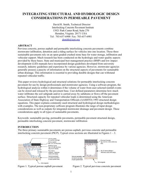
The three primary sustainable pavements are porous asphalt, pervious concrete <strong>and</strong> permeable<br />
interlocking concrete pavement (PICP). Typical cross sections are illustrated in Figures 1 – 3.<br />
Figure 1. Typical porous asphalt pavement<br />
Figure 2. Typical pervious concrete pavement<br />
1
Their hydrological design generally relies on the<br />
following variables:<br />
• design storm or storms, typically issued by the<br />
local stormwater agency<br />
• long-term soil infiltration rate, estimated from soil<br />
samples or field measured<br />
• base/subbase reservoir thickness <strong>and</strong> storage<br />
capacity<br />
Figure 3. Typical permeable interlocking concrete pavement (PICP)<br />
<strong>Hydrologic</strong>al design is patterned after infiltration trench design that accounts for rainfall entering<br />
directly into the pavement surface plus runoff from adjacent contributing pervious <strong>and</strong> impervious<br />
surfaces. Permeable/porous/pervious pavements may be designed to contain water for a few days for<br />
the purposes of nutrient reduction. In such cases, detention pond design principles can be applied to<br />
inflow, storage <strong>and</strong> outflow calculations. Excess water that cannot be contained by the base is<br />
allowed to exit via swales or bioretention areas adjacent to the pavement, through pipes in the base,<br />
<strong>and</strong>/or into catch basins. Figures 4, 5 <strong>and</strong> 6 illustrate some overflow options.<br />
Figure 4. Overflow to bioswale at Elmhurst<br />
College parking lot, Elmhurst, Illinois<br />
Figure 5. Catch basin overflow at Wal-mart<br />
parking lot Rehobeth Beach, Delaware<br />
For all permeable/porous/pervious pavements, the<br />
base/subbase thickness is determined for hydrological<br />
<strong>and</strong> structural (traffic loading) needs, <strong>and</strong> the<br />
thicker section is selected. <strong>Hydrologic</strong>al design for<br />
permeable/porous/pervious pavement is described in<br />
books <strong>and</strong> BMP manuals, but structural (base<br />
thickness) design is not due to a lack of information<br />
on the structural performance of open-graded bases<br />
used in them. This paper reviews structural design<br />
approaches for these pavements published by their<br />
representative industries <strong>and</strong> it presents some tools<br />
to integrate hydrological design.<br />
Figure 6. Outflow via perforated drain pipe is set to drain into a utility structure. The pipe is elevated<br />
above a low infiltration soil subgrade to detain water in the open-graded stone base, promote nutrient<br />
reduction <strong>and</strong> eventual infiltration.<br />
2
Inflow-Outflow Analysis<br />
Performed at 5 min. time intervals<br />
Pavement<br />
•Slope<br />
• Infiltration<br />
Amount of Rainfall<br />
•Storm pattern<br />
•Storm year<br />
Adjacent Areas<br />
•Size<br />
• Drainage properties<br />
Inflow Analyses<br />
Drainage Characteristics<br />
• Results of <strong>Structural</strong> Analysis<br />
• Porosity of pavement layers<br />
• Permeability of pavement layers<br />
• Subgrade infiltration<br />
• Drainage pipes<br />
• Layer thickness<br />
•Slopes, etc.<br />
Outflow Analysis<br />
• Amount of surface runoff<br />
• Depth of water on the pavement surface<br />
• Volume of water entering the pavement surface<br />
• Depth of water in pavement granular layers<br />
• Volume of water entering subgrade<br />
• Outflow through drains, etc.<br />
Consider changing<br />
• Drainage characteristics<br />
Yes<br />
Is the<br />
drainage<br />
adequate<br />
No<br />
Consider changing<br />
• Thickness of pavement granular layers<br />
To structural analysis<br />
Figure 8. <strong>Hydrologic</strong>al analysis flow chart for permeable pavement<br />
PICP <strong>Structural</strong> Analysis<br />
To assess the structural capacity of PICP, the program uses the AASHTO 1993 structural design<br />
equation to develop base thicknesses for supporting vehicular traffic. This design method relies on<br />
inputs such as traffic information, soils <strong>and</strong> pavement material information, reliability <strong>and</strong><br />
serviceability levels. As previously noted, the AASHTO empirical design method calculates a<br />
structural number (SN) which is the sum of layer coefficients, a dimensionless characterization of the<br />
stiffness of each pavement layer. <strong>Design</strong>ed for use in the United States <strong>and</strong> Canada, the user can<br />
instantly move from SI or U.S. customary units even while inputting data.<br />
To determine the thickness of the required pavement layers, layer coefficients (default values or<br />
those assigned by the user) determine if the open-graded base types <strong>and</strong> thicknesses meet the design<br />
structural number or design SN. While the user can change default values, the program assumes that<br />
layer coefficients for open-graded bases are lower than those associated with dense-graded bases<br />
used under conventional impervious pavements.<br />
The PICP paving layer thickness is consistently specified at 3 1/8 in. (80 mm) for the pavers plus 2 in.<br />
(50 mm) for the bedding layer. While a conservative default value of 0.3 per inch layer coefficient is<br />
assumed for the pavers <strong>and</strong> bedding layer, the user can nominate a paver-specific layer coefficient<br />
should it be available. Since the paving layer thickness is constant <strong>and</strong> its stiffness is characterized<br />
by this layer coefficient, only the open-graded base (usually the ASTM No. 57 stone held constant at<br />
4 in. or 100 mm thickness) <strong>and</strong> the subbase thickness (ASTM No. 2 stone layer) requires designing.<br />
The subbase thickness is rounded up to the nearest inch (25 mm) to ensure a reasonable <strong>and</strong><br />
conservative value for constructability. The software program applies to PICP subject to axle loads<br />
up to 24,250 lbs (11,000 kg) or a maximum vehicle load of 50,000 lb (22,680 kg) trafficked up to 1<br />
million 80 kN (18-kip) equivalent single axle loads (ESALs). Users are cautioned when the design<br />
load exceeds 600,000 ESALs. Figure 9 illustrates similar truck loads on a PICP project.<br />
7
INTEGRATING STRUCTURAL AND HYDROLOGICAL DESIGN IN PICP<br />
The designer can conduct sophisticated sensitivity analysis on structural <strong>and</strong> hydrological input<br />
variables using a software program recently released by the Interlocking Concrete Pavement Institute<br />
(ICPI 2008). The flow chart shown in Figure 7 illustrates the integration of hydrological <strong>and</strong><br />
structural design using this software. Like many software programs, this one enables the user to test<br />
the sensitivity of input variables with limited data <strong>and</strong> therefore design conservatively. Besides<br />
traffic loads <strong>and</strong> soil infiltration rates, other difficult-to-predict variables that can be modeled can<br />
include the long term surface infiltration rate, possible lower soil subgrade strengths when near<br />
saturation, antecedent water conditions in the base reservoir, as well as the long-term soil subgrade<br />
infiltration rate.<br />
<strong>Structural</strong> Analysis<br />
<strong>Hydrologic</strong>al<br />
Analysis<br />
Pavement Structure:<br />
Type <strong>and</strong> thickness of<br />
pavement layers<br />
Drainage <strong>Design</strong>:<br />
Drainage features<br />
<strong>and</strong> characteristics<br />
Yes<br />
Is the<br />
drainage<br />
adequate<br />
No<br />
Consider changing<br />
• Drainage characteristics<br />
Consider changing<br />
• Thickness of pavement<br />
granular layers<br />
Figure 7. An overview of structural <strong>and</strong> hydrological analysis for permeable pavement<br />
PICP <strong>Hydrologic</strong>al Analysis<br />
Figure 8 summarizes the hydrological modelling process. The hydrological analysis determines if the<br />
volume of water from user-selected rainfall events can be stored, infiltrated <strong>and</strong> released by the<br />
pavement structure. All water is modelled as a water balance using small time steps to characterize<br />
water inflow from precipitation into the PICP surface <strong>and</strong> runoff contributed from adjacent areas.<br />
The program holds a significant rainfall library for many cities in the U.S. <strong>and</strong> Canada consisting of<br />
5, 10, 25, 50 <strong>and</strong> 100 year return periods for 24 hour events.<br />
Besides characterizing contributing runoff from adjacent areas, the user can elect to include<br />
perforated drain pipes in the base to accommodate outflow in low infiltration soils. These can be<br />
modeled at the bottom of the subbase or raised within it to create some detention. The program also<br />
calculates the curve number <strong>and</strong> runoff coefficient for user selected rainfall events for the site.<br />
Outflow is also estimated by calculating infiltrated water flowing directly into the PICP <strong>and</strong> from<br />
contributing areas, as well as drainage from the base into the soil or to drainage pipes during each<br />
time step. The combined process continually estimates the water level in the base <strong>and</strong> the amount<br />
draining from the PICP, during <strong>and</strong> after the storm. Output includes hydrographs for the rainfall,<br />
inflow from contributing areas, infiltration <strong>and</strong> outflow through drain pipes if required. Output<br />
variables can be set for water storage <strong>and</strong> harvesting if needed.<br />
6
Traffic<br />
Load<br />
<strong>Design</strong><br />
Axle<br />
Load, lbs<br />
(kN)<br />
Repetitions<br />
Pervious Concrete<br />
Thickness, in.<br />
(mm)<br />
Low 4,000 (18) Unlimited 4 (100) Unlimited<br />
Moderate 12,000 (53)
The number of ESALs is determined by the weight of each of the axles <strong>and</strong> dividing them by a<br />
‘st<strong>and</strong>ard’ ESAL of 18,000 lbs (80 kN). A five axle tractor-trailer truck provides an example: two<br />
rear axles on the trailer each exert 18,000 lbs or 80 kN; two on the back of the truck at 15,800 lbs or<br />
70 kN; <strong>and</strong> one in the front (steering) at 11,000 lbs or 50 kN. AASHTO uses the following<br />
relationships called load equivalency factors or LEFs for each axle to estimate ESALs. LEF <strong>and</strong><br />
ESALs for this truck are as follows:<br />
Trailer: (80/80) 4 = 1 (x 2 axles) = 2 ESALs<br />
Truck rear: (70/80) 4 = 0.6 (x 2 axles) = 1.2 ESALs<br />
Truck front: (50/80) 4 = 0.15 ESALs<br />
When added together, all LEFs = 3.35 ESALs. For every pass across a pavement, this truck exerts<br />
3.35 18,000 lb (80 kN) ESALs. To put automobile axle loads into perspective, the weight of one<br />
passenger car placed into the formula yields about 0.0002 ESALs. Therefore, pavement design is<br />
primarily considers trucks because they exert the highest loads <strong>and</strong> most damage. In contrast,<br />
thous<strong>and</strong>s of cars are required to apply the same loading <strong>and</strong> damage as one passage of a truck.<br />
POROUS ASPHALT STRUCTURAL DESIGN<br />
Porous pavement thickness design is addressed in industry literature. Table 1 indicates thicknesses<br />
for porous asphalt design (NAPA 2008). This is excerpted from the National Asphalt Pavement<br />
Association porous asphalt manual which does not quantify maximum traffic loading.<br />
Minimum Compacted<br />
Thickness, in. (mm)<br />
Traffic Loading<br />
Parking – Little or no trucks 2.5 (65)<br />
Residential street – Some trucks 4.0 (100)<br />
Heavy Trucks 6 (150)<br />
Table 1. Minimum compacted porous asphalt thicknesses<br />
Regarding AASHTO layer coefficients per inch (25 mm) of pavement layer thickness for porous<br />
asphalt, NAPA (2008) recommends the following in Table 2.<br />
Material<br />
Layer Coefficient (per in.)<br />
Porous Asphalt 0.40 – 0.42<br />
Asphalt-treated permeable base 0.30 – 0.35<br />
Porous aggregate (open-graded) base 0.10 – 0.14<br />
Table 2. AASHTO layer coefficients for porous asphalt, treated base <strong>and</strong> open-graded base<br />
PERVIOUS CONCRETE STRUCTURAL DESIGN<br />
The National Concrete Ready Mix Association manual, <strong>Hydrologic</strong> <strong>Design</strong> of Pervious Concrete<br />
(2007 Leming) provides a methodology that utilizes the Natural Resource Conservation Service<br />
(NRCS) Curve Number method. The manual reviews software for hydrological calculations. While<br />
the software program does not include structural design, some recommendations are provided as<br />
charts in the appendix. Depending on axle loads, pavement thickness charts recommend 4, 6 <strong>and</strong> 8 in.<br />
(100, 150 <strong>and</strong> 200 mm) thick pervious concrete on soils with infiltration rates no lower than 0.1<br />
in./hr. (0.3 cm/hr).<br />
There is no design guidance on the thickness of open-graded base required for traffic load support.<br />
The user is directed to consulting a design professional (e.g. civil engineer) for determining pervious<br />
concrete <strong>and</strong> base thicknesses on soils less than 0.1 in./hr (0.3 cm/hr) infiltration rate. Table 3 below<br />
replicates the pavement thickness information by Leming. The right h<strong>and</strong> column is added by the<br />
author to demonstrate the ESAL ranges supported by the various pervious concrete pavement<br />
thicknesses. The design charts note that a design professional should be consulted for lifetime<br />
designs greater than 720,000 ESALs.<br />
4
BASIS FOR STRUCTURAL DESIGN<br />
For structural design of impervious (conventional) roads <strong>and</strong> base, many local, state <strong>and</strong> provincial<br />
agencies design methods published by the American Association of State Highway <strong>and</strong><br />
Transportation Officials (AASHTO). While the AASHTO methodology is familiar to some civil<br />
engineers, stormwater agency personnel who do not deal with pavement design are encouraged to<br />
become more familiar with them <strong>and</strong> reference them in permeable pavement design<br />
recommendations for local, state or provincial BMP <strong>and</strong> LID manuals, <strong>and</strong> regulatory documents.<br />
Highway engineers are increasingly using AASHTO 2002 Mechanistic-Empirical Pavement <strong>Design</strong><br />
Guide which relies on mechanistic design <strong>and</strong> modeling, i.e. analysis of loads <strong>and</strong> resultant stresses<br />
<strong>and</strong> strains on materials <strong>and</strong> the soil subgrade. The AASHTO 2002 mechanistic design model was<br />
developed <strong>and</strong> calibrated by state, provincial <strong>and</strong> federal highway agencies across a wide range of<br />
highway loads, load testing, soil types <strong>and</strong> climatic conditions. This model has not been calibrated<br />
for permeable pavements (subject to significantly less traffic loads) constructed with open-graded,<br />
crushed stone bases.<br />
Many local agencies use the empirically-based AASHTO 1993 Guide for <strong>Design</strong> of Pavement<br />
Structures whose underlying concepts emerged from test pavements in the 1950s repeatedly<br />
trafficked by trucks that established relationships among materials types, loads <strong>and</strong> serviceability.<br />
The AASHTO equation in the 1993 Guide calculates a <strong>Structural</strong> Number or SN given traffic loads,<br />
soil type, climate <strong>and</strong> moisture conditions. The designer then finds the appropriate combination of<br />
pavement surfacing <strong>and</strong> base materials to meet or exceed the <strong>Structural</strong> Number. This empirical<br />
design approach appears to be applicable to permeable pavements with consideration given to input<br />
variables.<br />
Due to their load distribution means, porous asphalt <strong>and</strong> PICP are considered flexible pavement<br />
systems <strong>and</strong> the flexible pavement design concepts in AASHTO can be applied to them. A key input<br />
for flexible pavement design is the layer coefficient which characterizes each pavement layer with a<br />
number. The higher the coefficient, the stiffer the material <strong>and</strong> the coefficient is expressed per inch<br />
or per millimeter of pavement layer thickness. The thickness of each material is multiplied by the<br />
layer coefficients <strong>and</strong> all coefficients are added to equal or exceed the <strong>Structural</strong> Number.<br />
For example, given site specific inputs on subgrade soil strength, climate, moisture <strong>and</strong> traffic loads<br />
into the AASHTO equation yields a required structural number of 2.5. The designer then identifies<br />
the combination of pavement layer materials whose layer coefficients total at least 2.5. In this<br />
illustration, a compacted, dense-graded crushed stone base typically has a layer coefficient of 0.14.<br />
Asphalt typically has a layer coefficient of 0.44. If 3 in. (75 mm) of asphalt are selected, then the SN<br />
for this layer is 0.44 x 3 = 1.32. The base layer thickness required would then be 2.5 – 1.32 =<br />
1.18/0.14 = 8.4 or about 9 in. (225 mm) which satisfies the required <strong>Structural</strong> Number.<br />
CHARACTERIZING TRAFFIC LOADS<br />
When a vehicle passes over a pavement, it damages it. The cumulative effects of many passes<br />
eventually causes ruts or cracks making the pavement unserviceable <strong>and</strong> needing rehabilitation.<br />
Vehicles passing over a pavement exert a wide range of loads. Compared to cars, trucks <strong>and</strong> busses<br />
do the most damage to pavements because their wheel loads <strong>and</strong> tire pressures are much heavier <strong>and</strong><br />
higher than cars. One pass of a fully loaded truck will do more damage to pavement than several<br />
thous<strong>and</strong> cars passing over it. The AASHTO Guide characterizes traffic loads as the number of<br />
18,000 lbs or 80 kN equivalent single axle loads or ESALs. The 18,000 lb load emerged from the<br />
AASHTO road tests conducted in the 1950s <strong>and</strong> has remained as a convenient means to quantify<br />
loads.<br />
3
CONCLUSION<br />
Stormwater agencies provide permeable<br />
pavement design guidelines through BMP<br />
<strong>and</strong> LID manuals <strong>and</strong> other publications.<br />
Most of the guidelines focus on design for<br />
managing stormwater <strong>and</strong> its pollutants.<br />
There is little information provided on<br />
structural design or it is imprecisely<br />
quantified. Better structural design<br />
information is needed to raise designer<br />
confidence. Compared to impervious<br />
pavement structural design, permeable<br />
pavement structural design is in its<br />
formative stages. Industry guidelines for<br />
each permeable pavement system should<br />
be followed with advice from a qualified<br />
design professional.<br />
Figure 9. PICP demonstrates an ability to support<br />
loaded trucks at Elmhurst College, Elmhurst, Illinois.<br />
The structural behavior of open-graded bases requires more research <strong>and</strong> testing to determine<br />
relationships between load <strong>and</strong> deformation (e.g., surface rutting <strong>and</strong>/or cracking). There is limited<br />
laboratory <strong>and</strong> field (accelerated traffic load) testing information on open-graded bases as reliable<br />
inputs for structural design. The AASHTO 1993 methodology appears to be a suitable empiricallybased<br />
design approach until more design data is developed from the structural response <strong>and</strong><br />
serviceability of permeable/porous/pervious pavements under a range of climates, soils <strong>and</strong> traffic.<br />
The author wishes to thank D. J. Swan with Applied Research Associates, Inc. for the flow charts in<br />
this paper.<br />
REFERENCES<br />
AASHTO 1993. Guide for <strong>Design</strong> of Pavement Structures, American Association of State Highway<br />
<strong>and</strong> Transportation Officials, Washington, DC.<br />
AASHTO 2002. Mechanistic-Empirical Pavement <strong>Design</strong> Guide, American Association of State<br />
Highway <strong>and</strong> Transportation Officials, Washington, DC.<br />
ICPI 2008. Applied Research Associates, Inc., Permeable <strong>Design</strong> Pro Software, Interlocking<br />
Concrete Pavement Institute, Herndon, Virginia.<br />
Leming 2007. Leming, M. L., Malcom, H. R., <strong>and</strong> Tennis, P. D., <strong>Hydrologic</strong> <strong>Design</strong> of Pervious<br />
Concrete, EB303, Portl<strong>and</strong> Cement Association, Skokie, Illinois, <strong>and</strong> National Ready Mixed<br />
Concrete Association, Silver Spring, Maryl<strong>and</strong>, 72 pages.<br />
NAPA 2008. Porous Asphalt Pavements for Stormwater Management, Information Series 131,<br />
National Asphalt Pavement Association, Lanham, Maryl<strong>and</strong>, 24 pages.<br />
Smith 2006. Smith, D. R., Permeable Interlocking Concrete Pavements – <strong>Design</strong> Specification<br />
Construction Maintenance, Interlocking Concrete Pavement Institute, Herndon, Virginia, 48 pages.<br />
8