1 BRIDGE CRANE SPECIFICATIONS AND STATEMENT OF WORK ...
1 BRIDGE CRANE SPECIFICATIONS AND STATEMENT OF WORK ...
1 BRIDGE CRANE SPECIFICATIONS AND STATEMENT OF WORK ...

You also want an ePaper? Increase the reach of your titles
YUMPU automatically turns print PDFs into web optimized ePapers that Google loves.
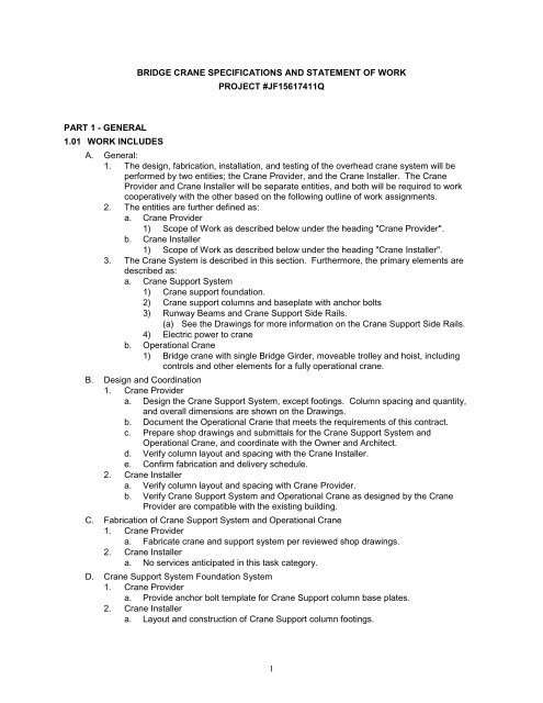
<strong>BRIDGE</strong> <strong>CRANE</strong> <strong>SPECIFICATIONS</strong> <strong>AND</strong> <strong>STATEMENT</strong> <strong>OF</strong> <strong>WORK</strong><br />
PROJECT #JF15617411Q<br />
PART 1 - GENERAL<br />
1.01 <strong>WORK</strong> INCLUDES<br />
A. General:<br />
1. The design, fabrication, installation, and testing of the overhead crane system will be<br />
performed by two entities; the Crane Provider, and the Crane Installer. The Crane<br />
Provider and Crane Installer will be separate entities, and both will be required to work<br />
cooperatively with the other based on the following outline of work assignments.<br />
2. The entities are further defined as:<br />
a. Crane Provider<br />
1) Scope of Work as described below under the heading "Crane Provider".<br />
b. Crane Installer<br />
1) Scope of Work as described below under the heading "Crane Installer".<br />
3. The Crane System is described in this section. Furthermore, the primary elements are<br />
described as:<br />
a. Crane Support System<br />
1) Crane support foundation.<br />
2) Crane support columns and baseplate with anchor bolts<br />
3) Runway Beams and Crane Support Side Rails.<br />
(a) See the Drawings for more information on the Crane Support Side Rails.<br />
4) Electric power to crane<br />
b. Operational Crane<br />
1) Bridge crane with single Bridge Girder, moveable trolley and hoist, including<br />
controls and other elements for a fully operational crane.<br />
B. Design and Coordination<br />
1. Crane Provider<br />
a. Design the Crane Support System, except footings. Column spacing and quantity,<br />
and overall dimensions are shown on the Drawings.<br />
b. Document the Operational Crane that meets the requirements of this contract.<br />
c. Prepare shop drawings and submittals for the Crane Support System and<br />
Operational Crane, and coordinate with the Owner and Architect.<br />
d. Verify column layout and spacing with the Crane Installer.<br />
e. Confirm fabrication and delivery schedule.<br />
2. Crane Installer<br />
a. Verify column layout and spacing with Crane Provider.<br />
b. Verify Crane Support System and Operational Crane as designed by the Crane<br />
Provider are compatible with the existing building.<br />
C. Fabrication of Crane Support System and Operational Crane<br />
1. Crane Provider<br />
a. Fabricate crane and support system per reviewed shop drawings.<br />
2. Crane Installer<br />
a. No services anticipated in this task category.<br />
D. Crane Support System Foundation System<br />
1. Crane Provider<br />
a. Provide anchor bolt template for Crane Support column base plates.<br />
2. Crane Installer<br />
a. Layout and construction of Crane Support column footings.<br />
1
E. Power for Crane System<br />
1. Crane Provider<br />
a. Coordinate power requirements for 5 ton crane with Architect and the Crane Installer.<br />
2. Crane Installer<br />
a. Verify power requirements for 5 ton crane with Crane Provider.<br />
b. Provide power to agreed upon connection point.<br />
F. Delivery of Crane Support System and Operational Crane<br />
1. Crane Provider<br />
a. Coordinate delivery of crane, crane support elements, and other related elements to<br />
be delivered directly to the Crane Installer.<br />
2. Crane Installer<br />
a. Coordinate receipt of crane, crane support elements, and other related elements to<br />
be delivered directly to the Crane Installer by the Crane Provider.<br />
b. Receive the crane, crane support elements, and other related elements.<br />
G. Installation of Crane Support System<br />
1. Crane Provider<br />
a. Verify the elements to be installed, their relationship to each other, and their<br />
relationship to the foundation installed by the Crane Installer.<br />
2. Crane Installer<br />
a. Install elements provided by the Crane Provider.<br />
H. Installation of Operational Crane<br />
1. Crane Provider<br />
a. Identify all elements that constitute the Operational Crane (perform this task during<br />
the preparation of shop drawings and submittals).<br />
1) Identify elements to be installed by the Crane Installer.<br />
2) Identify elements to be delivered by the Crane Provider.<br />
2. Crane Installer<br />
a. Install all elements identified by the Crane Provider to be installed by the Crane<br />
Installer.<br />
b. Coordinate with the Crane Provider for the elements to be delivered by the Crane<br />
Provider.<br />
I. Testing of Operational Crane<br />
1. Crane Provider<br />
a. Perform functional testing to verify the installed bridge crane meets the contract<br />
requirements and applicable codes and safety requirements.<br />
b. Adjust the installed crane as required to improve performance based on results of the<br />
functional testing.<br />
2. Crane Installer<br />
a. Coordinate with the Crane Provider during the functional testing.<br />
b. Coordinate with the Crane Provider during the modifications to the installed bridge<br />
crane.<br />
1.02 SCHEDULE<br />
A. Crane Support Structure and Operational Crane to be delivered to the Crane Installer with<br />
sufficient time to allow the Crane Installer 5 days to install the Crane Support Structure, 5 days<br />
to install the Operational Crane, and the time anticipated by the Crane Provider to provide<br />
sufficient time for testing and adjustment as required to turn the Operational Crane to the<br />
Owner by the date listed below.<br />
B. The Operational Crane to be tested, adjusted, and ready for owner's use by January 21, 2011.<br />
C. The Crane Provider to provide schedule of activities with dates to meet the schedule listed<br />
above.<br />
2
1.03 SYSTEMS DESCRIPTION<br />
A. The Crane Provider shall furnish the following:<br />
1. One approximately 46 foot span, top running, single girder, crane bridge. Crane to be<br />
designed and built per CMAA (Crane Manufacturer’s Association of America) standards<br />
per below.<br />
2. One wire rope hoist.<br />
3. Runway for an approximately 64 foot long runway bay. Runway supported on 32 foot<br />
centers by attaching directly to the top of the Steel Crane Rail. See the drawings for<br />
Runway Beam extension (cantilever) beyond end columns.<br />
B. The crane is to be installed in the location shown on the drawings.<br />
C. Coordinate all clearances with the existing building<br />
1.04 OPERATING <strong>SPECIFICATIONS</strong><br />
A. Capacity: 5 tons<br />
B. Duty Class: CMAA Class B<br />
C. Span: See drawings.<br />
D. Steel: AISC Hot Rolled Steel Beams, A-992.<br />
E. Bridge Girder Deflection: L/600<br />
F. End Trucks: Dual drive with fixed axles. Motors shall include AC magnetic disc brakes per<br />
CMAA requirements. Wheelbase-to-span ratio shall not exceed 7:1.<br />
G. Hoist: Low-Headroom, Electric wire rope hoist with a hook to block dimension not to exceed 16<br />
inches.<br />
H. Lifting Height: See the Drawings. The height shown is the minimum max height allowable,<br />
however the Owner prefers the most height achievable within the constraints of the existing<br />
building elements: Lifting height is above the operating floor with three wraps remaining on<br />
drum at lowest hook position.<br />
I. Trolley: Motor driven with two drive wheels and brakes per CMAA requirements.<br />
J. Speeds:<br />
1. Bridge: 100 (max) feet per minute, Variable Frequency Drive (VFD).<br />
2. Hoist: 20 (max) to 6 (min) feet per minute, 2-Speed.<br />
3. Trolley: 50 feet per minute, 2-Speed.<br />
K. Voltage: 460 v 3 Ph 60 Hz, 115 volt control.<br />
L. Bumpers: Rubber bumpers on end trucks and trolley per CMAA requirements.<br />
M. Enclosures: NEMA 4, Minimum.<br />
1.05 SUBMITTAL<br />
A. Submittals<br />
1. The Crane Provider shall submit the following:<br />
a. Product Data<br />
b. Operation and Maintenance Manuals<br />
c. Manufacturer’s Instructions<br />
d. List of Manufacturers and Model Numbers<br />
e. Spare Parts List<br />
f. Special Tools List<br />
g. Reports of Certified Shop Tests Performance Warranty<br />
h. Elements that constitute the Crane Support System.<br />
i. Elements that constitute the Operational Crane.<br />
1) Elements to be delivered by the Crane Provider<br />
2) Elements to be installed by the Crane Installer.<br />
B. Shop Drawings<br />
3
1. Each submittal shall be complete in all respects, incorporating all information and data<br />
listed herein and all additional information required for evaluation of the proposed<br />
equipment’s compliance with the Specifications.<br />
2. Shop drawings shall include but not be limited to:<br />
a. Elements that constitute the Crane Support System.<br />
b. Elements that constitute the Operational Crane.<br />
c. Equipment specifications and data sheets identifying all materials used and methods<br />
of fabrication.<br />
d. Complete assembly, layout and installation drawings with clearly marked dimensions.<br />
e. Installation and start-up instructions.<br />
f. Weights of all component parts, assembled weight of units and approximate total<br />
shipping weight.<br />
g. Example equipment nameplate data sheet.<br />
h. Interconnecting ladder-type wiring diagrams for power and control wiring required for<br />
final connections. Clearly differentiate between portions of wiring that are factory<br />
installed and portions to be field installed.<br />
i. List of recommended spare parts.<br />
C. Operations and Maintenance Manuals<br />
1. The Crane Provider shall submit operation and maintenance manuals.<br />
D. Tools, Supplies and Spare Parts – Crane Provider<br />
1. Furnish all special tools necessary to disassemble, service, repair and adjust the<br />
equipment.<br />
2. Spare parts shall be furnished as recommended by the equipment manufacturers.<br />
3. Parts shall be completely identified with a numerical system to facilitate parts inventory<br />
control and stocking. A separate number shall identify each part.<br />
4. Spare parts shall be delivered at the same time as the equipment to which they pertain.<br />
The Crane Provider will coordinate with the Crane Installer so that material is properly<br />
stored and safeguard such spare parts until completion of the work, at which time the<br />
spare parts, supplies and special tools shall be delivered to the Owner.<br />
1.06 QUALITY ASSURANCE<br />
A. All equipment and appurtenances furnished under this solicitation shall be equal to the named<br />
products and shall conform to the applicable requirements of the following:<br />
1. CMAA No. 74 - Crane Manufacturers Association of America<br />
2. ASME HST-4M-1996 - Performance Standard for Overhead Electric Wire Rope Hoists<br />
3. NEMA - National Electrical Manufacturers Association<br />
4. NEC - National Electrical Code<br />
B. All structural steel members of the handling system shall be designed in accordance with the<br />
specifications of the American Institute of Steel Construction, current edition and any welded<br />
construction shall be in accordance with the standard of the American Welding Society.<br />
1.07 DELEGATION <strong>OF</strong> DESIGN<br />
A. The Crane Provider, and/or the manufacturer, shall design, fabricate and provide a complete<br />
system as described in these specifications.<br />
B. Performance and Design Criteria: Where professional design services by a registered licensed<br />
design professional are required of the Crane Provider, by the Contract Documents or the<br />
Building Code, provide products and systems complying with the specific performance and<br />
design criteria included.<br />
C. D. The design of the Crane Support Structure and Operational Crane shall be completed under<br />
the direct supervision of an Oregon Registered/Licensed Structural Engineer who shall stamp<br />
and sign the design drawings and calculations for the Crane system.<br />
4
1.08 BUILDING PERMIT SUBMITTAL<br />
A. Crane Provider shall submit copies of the architect reviewed shop drawings and structural<br />
calculations for the Crane Support System and Operational Crane, verifying that they have<br />
been stamped by an Oregon Registered Structural Engineer, to the OSU Authorized<br />
Representative, who will submit to the Building Department as Supplemental Information to the<br />
Building Permit.<br />
1. Submit sufficient copies as required by the Building Department.<br />
B. The OSU Authorized Representative will provide a copy of the Building Department Approved<br />
plans to the Crane Installer for their use on the site with the original permit set.<br />
C. The Crane Installer shall coordinate Building Department Inspections during installation.<br />
1.09 SERVICES <strong>OF</strong> MANUFACTURER'S REPRESENTATIVE<br />
A. The Crane Provider shall furnish qualified technical representatives from the manufacturer(s)<br />
supplying equipment under this specification. Manufacturer(s) services shall include:<br />
1. Furnishing the services of a technical representative as required during the installation<br />
phase of the equipment. The factory representative shall have full knowledge and<br />
experience in the installation of the type of equipment being installed. If more time is<br />
required because of Crane Provider’s activities or problems with equipment, additional<br />
time is at Crane Provider’s expense.<br />
2. Furnishing the services of a technical representative that has complete knowledge of the<br />
operational and maintenance requirements of the system. The factory representative shall<br />
instruct the Owner’s personnel in the proper operation of the equipment in up to 6 hours of<br />
on-site training. If more time is required because of Crane Provider's activities or problems<br />
with equipment, additional time is at Crane Provider’s expense.<br />
1.10 WARRANTY<br />
A. Provide Manufacturer’s standard one year warranty on all installed parts.<br />
1.11 TRAINING<br />
A. Provide one day, on-site training for owner’s designated operators. Training to be videotaped<br />
and a digitally-formatted recording to be provided to owner. Training to include 8 copies of<br />
training manuals.<br />
PART 2 - PRODUCTS<br />
2.01 DESIGN REQUIREMENTS<br />
A. Materials shall be properly selected for the stresses to which they will be subjected. Load<br />
carrying parts, except girders shall be designed so that the calculated static stress in the<br />
material, based on rated load, shall not exceed 20 percent of the published average ultimate<br />
strength of the material. This limitation of stress provides a margin of strength to allow for<br />
variations in the properties of materials and under no condition should imply authorization or<br />
protection for user to load the crane beyond capacity. Girders shall be designed in accordance<br />
with CMAA No. 74 Specifications.<br />
2.02 MANUFACTURERS<br />
A. Yale Hoist; www.yaleproducts.com<br />
B. Budgit Hoist; www.budgithoist.com<br />
C. Shaw Box<br />
D. Substitutions: Substitution requests that meet the performance standards of these<br />
specifications and specified products will be considered.<br />
2.03 EQUIPMENT <strong>AND</strong> MATERIALS<br />
A. Furnish and coordinate installation as noted above a completed motorized top running 5-ton<br />
capacity crane system, together with crane rails, supports, hangers and accessories necessary<br />
for a complete functional installation.<br />
B. Crane Bridge<br />
5
1. General<br />
a. Design calculations for bridge girder stresses shall include all live and dead loads and<br />
live and dead load impacts and shall follow the method of calculation as prescribed<br />
by the Crane Manufacturer’s Association of America (CMAA).<br />
b. A safety factor of 5:1 shall be applied to the design of all load-bearing parts of the<br />
crane bridge, hoist and trolley.<br />
c. The rated capacity of the crane shall be the load that the crane is designed to carry<br />
as specified by the manufacturer and shown in tons on large capacity plates located<br />
on each side of the crane bridge. The crane bridge will be designed and built to<br />
handle this rated load plus the weight of the hoist, trolley and all handling accessories<br />
such as buckets, magnets, grabs, etc., shall be included as part of the load to be<br />
handled.<br />
d. Materials shall be specified herein and shall be free from all defects and<br />
imperfections that may affect the finished product. All parts shall be new and unused.<br />
1) Structural steel shall be of good commercial quality conforming to ASTM<br />
specification A36.<br />
2) End trucks shall be fabricated from tubes, structural steel shapes and plates<br />
welded into an integral unit and in-line bored to receive the wheel axles.<br />
3) Bearings shall be anti-friction ball or roller type, oil splash lubricated or equipped<br />
with easily lubrication fittings<br />
e. The bridge shall be a single girder, top-running, dual drive structure comprised of the<br />
girder, side rail (if necessary per engineering by Crane Provider) end trucks, drive<br />
units, and control panel and electrification system. The bridge shall be designed and<br />
fabricated as a complete integral structure with only such parts removable as<br />
required to facilitate the erection and maintenance of equipment.<br />
f. The bridge girder shall be constructed of standard structural shapes or boxed<br />
sections, reinforced and welded as required. Connections between the girder and<br />
end trucks can be either welded or bolted after installation and squaring.<br />
g. The end trucks will have a minimum wheelbase of 1/8 of the crane’s span. Each end<br />
truck will be carried on two (2) wheels running on anti-friction bearings. Wheels will<br />
be of machined steel, hardened to 300 –320 BHN, double flanged and capable of<br />
running on either ASCE or square bar runway rails. The end trucks will be provided<br />
with rubber bumpers at each end to engage end stops on the crane runway.<br />
2. Bridge drive<br />
a. The crane bridge shall be driven by two drives. One located on and driving one<br />
wheel on each end truck. Each drive shall consist of a drive gear reducer, a TENV,<br />
crane duty, 30 minute rated motor with class F insulation and means of braking to<br />
meet the requirements of OSHA.<br />
3. Bridge control panel<br />
a. The bridge motion’s control shall be located in a bridge-mounted NEMA4/12<br />
enclosure. The bridge control is to be provided with a mainline contactor controlled<br />
from the bridge control station and a door-mounted disconnect that turns off power to<br />
the bridge panel and drives and the hoist and trolley panel and drives before the<br />
panel door can be opened.<br />
b. The control shall be designed and built per the National Electric Code (NEC)<br />
standards with color-coded and match-marked wires. The panel shall also meet the<br />
standards of an independent certification agency.<br />
4. Crane Motion Control<br />
a. All motions of the crane (hoist, trolley and bridge) shall be operated through a single<br />
cable suspended pendant pushbutton type control. The pendant shall have two<br />
buttons for the control of each motion plus power on/off buttons:<br />
1) Hoist - Up/Down<br />
2) Trolley - Left/Right<br />
6
3) Bridge - Forward/Reverse<br />
4) Power - On/Off<br />
b. The pendant shall be suspended from:<br />
1) A separate “C” Track roving pendant.<br />
c. Pushbutton station shall be of molded contour grip type and supported from hoist by<br />
strain relief cable to avoid damage from pull on the control wires. The enclosure is to<br />
be NEMA 4X watertight. Controls pendant shall be 115 volt AC, supported by a<br />
strain cable. Pendant shall hang to a point 3'' - 6" above the operating floor elevation<br />
as shown on the drawings. The pushbuttons shall return to the off position when the<br />
operator releases the pressure. The magnetic contactors for all motions shall be<br />
mechanically or electrically interlocked. Control voltage at the pushbutton stations<br />
shall be grounded to the hoists. A strain reliever cable shall support the control<br />
pendant.<br />
1) Provide a remote push button station/operator/controls.<br />
5. Crane Bridge Electrification<br />
a. Power and control voltage will be provided to the moving trolley and hoist through<br />
means of a festoon flat cable system. There will be separate cables for the motor<br />
power supply (line voltage) and control and these cables will be provided with<br />
separate connecting fittings and plugs. The cable connecting fittings and plugs shall<br />
be metal, not plastic, and will be of the type easily repairable or modified in the field<br />
without special tools. The power and control cables will be carried from trolleys with<br />
four (4) steel wheels running in a track suspended off of the bridge girder running the<br />
full length of the crane span.<br />
b. The bridge will be provided with a main power pick-up (collector pole) and sliding<br />
shoe collectors that will contact and run in the shielded bar runway conductor system.<br />
6. Crane Runway System<br />
a. Runway Beams<br />
1) Runway beams will be provided by the Crane Provider, supported on stools<br />
welded to the building columns. The beams will be capped or uncapped as<br />
required to achieve maximum hook lift and to handle the crane’s loading<br />
(Equivalent center loading, E.C.L.) at full capacity load and closest hook<br />
approach possible. The ends of the runway beams are to be joined together by<br />
means of bolted splices.<br />
b. Runway Rails<br />
1) ASCE runway rails will be provided and installed on the runway beams. The<br />
rails will be properly sized for the crane’s intended service class, wheel diameter<br />
and loading and are to be secured to the top of the runway beams with J-bolts to<br />
permit future adjustments as needed. Bolted rail splices will be used to join the<br />
ends of the rail together and end stops will be provided at each end of the rails<br />
to engage with the bridge end truck bumpers.<br />
c. Runway Electrification<br />
1) Runway power electrification will be provided running the full length on one side<br />
of the runway. The electrification will be of the shielded bar type supported at<br />
proper intervals to prevent sag or excessive vibration and with power feeds<br />
located to minimize voltage drop so as to provide adequate power to operate at<br />
least the hoist and one traverse motion at the extreme ends of the runway.<br />
2) Provide four bar runway electrification system, Duct-O-Bar or approved. 3 line<br />
conductors are to be connected to the bridge via collectors. 1 line conductor for<br />
ground is to be connected to the bridge via similar collectors for a complete code<br />
approved installation.<br />
C. Electric Wire Rope Hoist<br />
1. Trolley and Hoist Specifications<br />
a. The electric motor-operated hoist and trolley shall be designed to meet the standards<br />
listed in this section:<br />
7
. Headroom required shall not exceed 30 inches from the bottom of the bridge beam to<br />
the throat of the load hook.<br />
c. Wire rope hoist shall meet the requirements of ASME B30.16 “Overhead Hoists”.<br />
Hoist shall be heavy duty meeting H4 Service classification as defined in ANSI/ASME<br />
HST-4M “Performance Standard for Overhead Electric Wire Rope Hoists”. Hoist shall<br />
be SHAW-BOX Motor Driven Trolley hoist, as manufactured by Lift-Tech International<br />
or approved. Electric wire rope hoists shall meet the following requirements.<br />
d. Frame shall be fabricated from rolled steel to form a one-piece weldment.<br />
e. Gear case is to be machined aluminum alloy casting with sealed construction<br />
allowing the gears and load brake to operate in a bath of oil.<br />
f. Bearings shall be high quality anti-friction type of either needle or ball design and<br />
used throughout the hoist. Bearings, not considered lifetime lubricated by the<br />
manufacturer, should be provided with a means for lubrication.<br />
g. Brakes: Hoist shall have (2) types of brakes: One DC electrical multiple disc motor<br />
brake spring set electrically released, and one self-adjusting Weston type mechanical<br />
load brake located in the gear case. Either brake shall have the capability of holding<br />
rated load in the event of failure of either brake system.<br />
h. Overload device shall be provided to prevent lifting excessive overloads. This loadlimiting<br />
device shall be preset at the factory to disengage the hoist motor from the<br />
gearing in event of excessive overload condition. Overload device is to be located<br />
between the motor and load brake, so that the load brake will hold the load in event<br />
of overload device failure.<br />
i. Motors shall be of high starting torque type designed specifically for hoist duty service<br />
with permanently lubricated ball bearings, rated for 30-minute duty cycle. The motor<br />
enclosure is to be totally enclosed non-ventilated, TENV. Motor insulation shall be<br />
class F Minimum. If hoist is to be two-speed it shall have a high speed to low speed<br />
ratio of 3:1. Motor is to have automatic reset temperature actuated switch (TAS) in<br />
motor windings to provide motor running over current protection.<br />
j. Gearing shall be a combination of spur and/or helical, precision cut and heat treated<br />
to ensure quiet, efficient operation. Gears shall be totally enclosed and run in a bath<br />
of oil to provide maximum lubrication. Gears are either splined or keyed to shafts.<br />
k. Deep grooved, large diameter rope drum that helps prevent over wrap of cable for<br />
longer rope life.<br />
l. The diameter of the rope drum shall not be less than 18 times the diameter of<br />
hoisting cable, running sheaves not be less than 16 times and idler sheave not less<br />
than 12 times the diameter. Hoisting cable shall be 6 x 37 improved plow steel.<br />
m. Limit Switch: An upper block operated control circuit limit switch shall be provided that<br />
shuts off the hoist motor when the load hook reaches its highest position. n.<br />
Controls to be centralized and designed per NEC (National Electric Code)<br />
standards housed in a panel with a hinged door. The controls are to be provided with<br />
a step-down transformer within the panel that provides 120 volts power to the control<br />
circuits. Control circuit voltage to the push button station shall not exceed 120 volts.<br />
In addition, the panel will meet the standards of an independent certification<br />
organization.<br />
o. Pushbutton station shall be of molded contour grip type and supported from hoist by<br />
strain relief cable to avoid damage from pull on the control wires. The enclosure is to<br />
be NEMA 4X watertight. Controls pendant shall be 115 volt AC, supported by a<br />
strain cable. Pendant shall hang to a point 3' - 6" above the operating floor.<br />
1) If available, provide a remote push button station/operator/controls.<br />
p. All controls, including power transformer, shall be housed in NEMA 412 enclosure<br />
mounted in an easily accessible location on the hoist. Controls shall include trolley<br />
travel and hoist raising and lowering. Limit switches shall be provided to prevent over<br />
travel of the hook in either direction. Motors shall be fully enclosed 30-minute duty<br />
cycle motors in a NEMA frame rated for 208 volts, 3-phase, 60 Hz power supply.<br />
8
q. Motor driven trolleys are to have heavy section rolled steel side frames. The wheels<br />
are steel with heat-treated (universal/patented track) tread. Motor driven trolleys have<br />
totally enclosed non-ventilated (TENV) motors with right angle gear reducers. Trolley<br />
wheel gears and pinions have machined cut gear teeth. Spacer washers are provided<br />
for trolley adjustments to various beam sizes.<br />
2. Electrical<br />
a. Under this section furnish controls from the wall mounted disconnect switch. Wiring,<br />
disconnect switch, and conduit to Duct-O-Bar to be provided by Crane Provider.<br />
b. The sizing and selection of electric crane motors shall be the full and undivided<br />
responsibility of the crane manufacturer in order to ensure complete coordination of<br />
the components and to provide unit responsibility.<br />
c. Any reference to motor size or power requirements for the crane motors contained in<br />
this specification section is preliminary and shall not be relied on by the Crane<br />
Provider. The Crane Provider shall be responsible for any changes to the electrical<br />
system that may result from final sizing and selection of the crane motors by the<br />
crane manufacturer at no additional cost to the Owner.<br />
d. Motor: All motors shall be furnished and installed under this section. All motors shall<br />
be of the standard efficiency totally enclosed non-ventilated squirrel cage type for 208<br />
volts, 3-phase, 60 Hz. All motors shall be of ample size and construction to carry<br />
continuously all loads, which may be imposed through their full range of operation.<br />
The maximum motor loading shall not exceed the nameplate horsepower rating,<br />
exclusive of service factor. Motor horsepower is to be determined by the Crane<br />
Provider. All motors shall operate at speeds not greater than that described herein.<br />
e. Electrical Controls: Furnish and install all motors and drives herein specified under<br />
this section. The Crane Provider shall also furnish all necessary wiring diagrams and<br />
instructions for proper wiring of equipment.<br />
3. Acceptable Manufacturer<br />
a. Monorail, trolley and hoist shall be Shaw-Box or approved equal.<br />
2.04 IDENTIFICATION<br />
A. Provide equipment identification.<br />
2.05 LUBRICANTS<br />
A. The manufacturer shall submit a list with a minimum of four manufacturer's standard lubricants,<br />
which may be used interchangeably for each type of lubricant required<br />
2.06 FINISH<br />
A. Crane Support System Elements<br />
1. Primer: MPI (Master Painter Institute) 5.1C W.B. Dry Fall: Alkyd Metal Primer MPI #76 or<br />
79, W.B. Dry Fall MPI #118 or 133.<br />
B. Operational Crane Elements<br />
1. Crane manufacturer's standard system.<br />
PART 3 - EXECUTION<br />
3.01 FIELD VERIFICATION<br />
A. The Crane Provider shall verify all field dimensions for the top-running crane to be installed and<br />
correct conditions detrimental to the proper and timely completion of work. The Crane Provider<br />
shall not proceed with delivery of the crane until unsatisfactory conditions have been corrected.<br />
3.02 FINISH<br />
A. Except for touch up, all painting shall be done in the shop.<br />
B. Crane Support System Elements<br />
1. Remove Grease, Oil, Dirt, Loose Rust, Loose Mill Scale, and any other bond-reducing<br />
Materials. All structural steel shall be cleaned of rust and mill scale with a minimum<br />
SSPC-6 “commercial blast” cleaning.<br />
2. Apply prime finish per MPI standards<br />
9
C. Operational Crane Elements<br />
1. The Operational Crane shall be primed and finish coated in accordance to manufacturer's<br />
specifications.<br />
2. Hoists shall be painted per the Hoist manufacturer’s standard coating. Hooks shall not be<br />
painted.<br />
3.03 INSTALLATION<br />
A. The Crane Provider shall coordinate the delivery and installation of the Crane Support System<br />
and Operational Crane per the requirements contained within regarding the delineation of the<br />
work, and per the manufacturer's standards.<br />
B. Arrange to have the manufacturer or supplier, of the equipment furnished under this section,<br />
furnish the services of a competent factory-trained and properly certified personnel to supervise<br />
the installation and initial operation.<br />
C. The Crane Installer shall Install and erect all assemblies and components in accordance with<br />
the details indicated on the approved shop drawings and the printed instructions of the<br />
manufacturer.<br />
3.04 TESTING<br />
A. An independent testing agency will perform special inspection for structural welding in<br />
accordance with OSSC 1701.5.5.1. The owner will retain the services of the testing agency.<br />
The structural engineer retained by the Crane Provider to engineer the Crane Support System<br />
to identify the elements that require special inspection.<br />
B. Testing shall comply with rules and coordination with inspectors of OSHA, City of Corvallis,<br />
OSU Environmental Health and Safety, and other applicable agencies.<br />
C. Field Testing: After approved equipment is installed, it shall be given a running test where it<br />
shall demonstrate the ability to lift and continuously transport the rated capacity throughout the<br />
entire length and width of the specified ranges.<br />
3.05 USE DURING CONSTRUCTION<br />
A. Use of system is not permitted during construction.<br />
3.06 CLEANING<br />
A. Prior to acceptance of the work, the Crane Provider will thoroughly clean all installed materials,<br />
equipment and related areas.<br />
END <strong>OF</strong> SECTION<br />
10


![SOU Diversions Addendum _1[1]. - Oregon University System](https://img.yumpu.com/43178123/1/190x245/sou-diversions-addendum-11-oregon-university-system.jpg?quality=85)