Electromode RFI Series Installation Manual
Electromode RFI Series Installation Manual
Electromode RFI Series Installation Manual

Create successful ePaper yourself
Turn your PDF publications into a flip-book with our unique Google optimized e-Paper software.
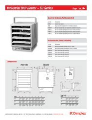
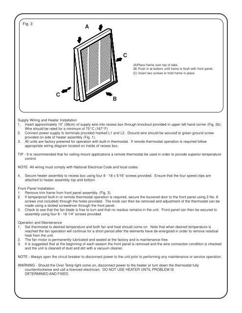
Fig. 3<br />
A<br />
C<br />
(A)Place frame over top of tabs.<br />
(B) Push in at bottom until frame is flush with front panel.<br />
(C) Insert two screws to hold frame in place.<br />
C<br />
B<br />
Supply Wiring and Heater <strong>Installation</strong><br />
1. Insert approximately 15” (38cm) of supply wire into recess box through knockout provided in upper left hand corner (Fig. 2b).<br />
Wire should be rated for a minimum of 75°C (167°F)<br />
2. Connect power supply to terminals provided marked L1 and L2. Ground wire should be secured to green ground screw<br />
provided on side of heater assembly (Fig. 1).<br />
3. All units are factory prewired for operation with built-in thermostat. If remote thermostat operation is required follow<br />
appropriate wiring diagram located on inside of recess box.<br />
TIP - It is recommended that for ceiling mount applications a remote thermostat be used in order to provide superior temperature<br />
control.<br />
NOTE -All wiring must comply with National Electrical Code and local codes.<br />
4. Secure heater assembly to recess box using four 8 - 18 x 5/16” screws provided. Ensure that the four speed clips are<br />
attached to heater assembly top and bottom.<br />
Front Panel <strong>Installation</strong><br />
1. Remove trim frame from front panel assembly. (Fig. 3)<br />
2. If tamperproof built-in or remote thermostat operation is required, secure the louvered door to the front panel using 2 No. 6<br />
screws (not included) through the holes provided. The knob can then be removed and adjustment of the thermostat can be<br />
made using a slotted screwdriver through the front panel.<br />
3. Check to see that the fan blade is free to turn and that no residue remains in the unit. Front panel can then be secured to<br />
assembly using four 8 - 18 1/4” screws provided.<br />
Operation and Maintenance<br />
1. Set thermostat to desired temperature and both fan and heat should come on. Note that when desired temperature is<br />
reached the fan operation will continue for a short period after the elements have de-energized in order to remove residual<br />
heat from the unit.<br />
2. The fan motor is permanently lubricated and sealed at the factory and is maintenance free.<br />
3. It is suggested that at the beginning of each season the front panel is removed and the wire connection condition is checked<br />
and the unit is cleaned of dust and dirt with a vacuum cleaner.<br />
NOTE - Always open the circuit breaker to disconnect power to the unit prior to performing any maintenance or service operation.<br />
WARNING - Should the Over Temp light come on, disconnect power to the heater or turn down the thermostat fully<br />
counterclockwise and call a licenced electrician. DO NOT USE HEATER UNTIL PROBLEM IS<br />
DETERMINED AND FIXED.