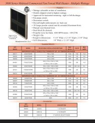
5100 Series Horizontal or Vertical Mounted Fan Forced Unit Heater
5100 Series Horizontal or Vertical Mounted Fan Forced Unit Heater
5100 Series Horizontal or Vertical Mounted Fan Forced Unit Heater
- No tags were found...

Create successful ePaper yourself
Turn your PDF publications into a flip-book with our unique Google optimized e-Paper software.
B<br />
A<br />
UH <strong>Series</strong> <strong>H<strong>or</strong>izontal</strong> <strong>Fan</strong> F<strong>or</strong>ced <strong>Unit</strong> <strong>Heater</strong><br />
3.3 KW THROUGH 48 KW HORIZONTAL DISCHARGE SUSPENDED FAN FORCED UNIT HEATERS<br />
AVAILABLE IN 1 OR 3 PHASE FOR ALL STANDARD VOLTAGES FROM 208V TO 480V.<br />
Manufactured in U.S.A.<br />
NOTE: Louver assembly is square and mounted with<br />
screws. Louver can be removed and repositioned f<strong>or</strong> four<br />
(4) directional air flow - left - right - up - down with the<br />
heater in the h<strong>or</strong>izontal position.<br />
FACTORY INSTALLED OPTIONS:<br />
• 24 Volt transf<strong>or</strong>mer on 3 KW to 15KW units to<br />
convert from line voltage to low voltage remote<br />
thermostat operation.<br />
• Summer fan switch to operate the fan only.<br />
• <strong>Fan</strong> Delay Switch to purge all residual heat from the<br />
unit after the heating element has cycled off.<br />
• Powder coated Epoxy finish f<strong>or</strong> c<strong>or</strong>rosive atmospheres.<br />
• Disconnect switch.<br />
MAXIMUM RECOMMENDED MOUNTING<br />
HEIGHT<br />
3 - 10 KW 9 FT.<br />
12 - 15 KW 10 FT.<br />
20 - 30 KW 13 FT.<br />
40 - 48 KW 16 FT.<br />
Product Dimensions & Model Number Designation<br />
A<br />
B B A<br />
3.3 KW THROUGH 15 KW UNIT HEATERS 20 KW THROUGH 48 KW UNIT HEATERS<br />
CONSTRUCTION:<br />
Heavy Gauge welded steel cabinet with powder coated finish and control<br />
compartment with a hinged and latched access do<strong>or</strong>, simplifying wiring<br />
installation & maintenance.<br />
HEATING ELEMENT:<br />
Circular copper clad steel sheath element with continuously brazed steel fins<br />
f<strong>or</strong>med to match the air delivery pattern of the fan blade.<br />
OVERHEAT PROTECTION:<br />
All units come equipped with automatic resetting type limit controls to deenergize<br />
the heater should an over-temperature situation occur.<br />
FAN and MOTOR:<br />
Totally enclosed, single phase, permanently lubricated, thermally protected<br />
mot<strong>or</strong>s with unit bearings on 3 KW - 10 KW models and sleeve bearings on 12.5<br />
KW - 48 KW models - mounted with rubber insulat<strong>or</strong>s to minimize vibration and<br />
noise. <strong>Fan</strong> assembly enclosed by a heavy gauge, close spaced, chrome plated<br />
wire guard.<br />
LOUVER ASSEMBLY:<br />
Louvers are individually adjustable f<strong>or</strong> directional control of air flow and the<br />
entire assembly can be repositioned in the field from down flow to up flow <strong>or</strong><br />
left / right directional air flow.<br />
TEMPERATURE CONTROLS:<br />
20 KW through 48 KW units and all 480V have built in 24 Volt transf<strong>or</strong>mer<br />
f<strong>or</strong> low voltage remote thermostat application. 25 KW through 48 KW models<br />
available in 2-stage on special <strong>or</strong>der (consult fact<strong>or</strong>y).<br />
INSTALLATION:<br />
<strong>Unit</strong> <strong>Heater</strong>s can be mounted with the mot<strong>or</strong> shaft from h<strong>or</strong>izontal to downward<br />
at 45° off h<strong>or</strong>izontal. Pre-drilled holes and installed threaded nuts provided to<br />
allow hanging by threaded rods - 1/4” f<strong>or</strong> units up to 15 KW and 5/16” f<strong>or</strong> 20<br />
KW units and larger. Optional wall / ceiling mounting brackets are available f<strong>or</strong><br />
all units.<br />
Figures 3 & 4 shown with standard mounting tabs f<strong>or</strong> units over 20 KW. Optional UHB-3 and UHB-4 wall brackets are available. 3.3 KW<br />
thru 15 KW units can be mounted using 1/4” threaded rod. 20 KW thru 48 KW units can be mounted using 5/16” threaded rod.<br />
HOW TO DESIGNATE A MODEL:<br />
H 2 H UH 10 C A 1<br />
Dimensions A B C<br />
Figure 1:<br />
3.3, 5, 7.5, 10 KW<br />
20” 11” 13”<br />
Figure 2:<br />
12.5, 15 KW<br />
22” 11” 15”<br />
Figure 3:<br />
20, 25, 30 KW<br />
24” 17” 17”<br />
Figure 4:<br />
40, 48 KW<br />
26” 23” 19”<br />
Element Volts<br />
F = 208<br />
H = 240<br />
HF = 240/208<br />
G = 277<br />
P = 480<br />
Phase<br />
1 = 1-Phase<br />
2 = 1 <strong>or</strong> 3-Ph.<br />
3 = 3-Phase<br />
Mot<strong>or</strong> Voltage<br />
F = 208<br />
H = 240<br />
B = 240 / 208<br />
G = 277<br />
P = 480<br />
Model <strong>Series</strong><br />
UH<br />
Element KW<br />
Control System<br />
O = None<br />
C = Contact<strong>or</strong><br />
R = Relay<br />
Transf<strong>or</strong>mer<br />
O = None<br />
A = Included<br />
Control Volts<br />
1 = 24<br />
2 = 120<br />
3 = Element Voltage<br />
4 = 240<br />
Fact<strong>or</strong>y Installed Options (use as a suffix on model designation):<br />
S = Summer <strong>Fan</strong> Switch, F = <strong>Fan</strong> Delay, D = Disconnect, T = Built-in Thermostat, E = Epoxy Coated<br />
Field Installed Options:<br />
Disconnect Switch, Built-in Thermostat, & Wall / Ceiling Bracket<br />
Markel Products Company
UPC#<br />
686334<br />
UH <strong>Series</strong> <strong>H<strong>or</strong>izontal</strong> <strong>Fan</strong> F<strong>or</strong>ced <strong>Unit</strong> <strong>Heater</strong><br />
Standard Product Models<br />
MODEL KW BTU'S VOLTS PH AMPS<br />
CONTROL<br />
VOLTS<br />
TEMP<br />
RISE °F<br />
Fact<strong>or</strong>y & Field Installed Access<strong>or</strong>ies<br />
AIR<br />
THROW CFM<br />
RECOM'D<br />
MOUNTING<br />
HT.<br />
644600 F1FUH03003<br />
208 1 16 208<br />
644662 H1HUH03003 240 1 14 240<br />
644723 G1GUH03003 277 1 12 277<br />
3.3 11,200<br />
711487 H3HUH03C03 240 3 8 240<br />
26 26' 400<br />
36<br />
711494 F3FUH03C03 208 3 9 208<br />
711401 P3PUH03CA1 480 3 4 24<br />
644617 F1FUH05003<br />
208 1 24 208<br />
644679 H1HUH05003 240 1 21 240<br />
36<br />
644730 G1GUH05003 277 1 18 277<br />
5 17,100<br />
644938 F2FUH05C03 208 1 <strong>or</strong> 3 24.1/14.0 208<br />
40 26' 400<br />
644945 H2HUH05C03 240 1 <strong>or</strong> 3 20.8/12.1 240<br />
44<br />
644884 P3PUH05CA1 480 3 6 24<br />
644624 F1FUH07CA1<br />
208 1 36 24<br />
9' 40<br />
688550 H1HUH07CA1 240 1 31 24 41<br />
644747 G1GUH07CA1 7.5<br />
277 1 27 24 41<br />
25,600<br />
42 36' 575<br />
644792 F3FUH07C03 208 3 21 208<br />
644952 H2HUH07C03 240 1 <strong>or</strong> 3 31.3/18.1 240<br />
44<br />
644891 P3PUH07CA1 480 3 9 24<br />
644631 F1FUH10CA1<br />
208 1 48 24<br />
644693 HIHUH10CA1 240 1 42 24<br />
10 34,100<br />
644754 G1GUH10CA1 277 1 36 24<br />
55<br />
42<br />
644969 F2FUH10C03 208 1 <strong>or</strong> 3 48.1/27.8 208<br />
36' 575<br />
644976 HF2HUH10C03 10/7.5<br />
34,100 240 1 <strong>or</strong> 3 41.7/24.1 240 55<br />
25,600 208 1 <strong>or</strong> 3 36.1/20.8 208 42<br />
45<br />
711425 P3PUH10CA1 10 34,100 480 3 12 24 55 51<br />
644648 F1FUH12C03<br />
208 1 60 208<br />
644709 H1HUH12C03 240 1 52 240<br />
644815 F3FUH12C03 12.5 42,600 208 3 35 208 49 45' 800<br />
45<br />
644860 H3HUH12C03 240 3 30 240<br />
711432 P3PUH12CA1 480 3 15 24<br />
644655 F1FUH15CO3<br />
208 1 72 208<br />
10'<br />
644716 H1HUH15C03 240 1 63 240<br />
644822 F3FUH15C03 15 51,200 208 3 42 208 59 45' 800 54<br />
644877 H3HUH15C03 240 3 36 240<br />
711449 P3PUH15CA1 480 3 18 24<br />
688307 F1FUH20CA1<br />
208 1 96 24<br />
688420 H1HUH20CA1 240 1 83 24<br />
688314 F3FUH20CA1 20 68,300 208 3 56 24 47 56' 1350<br />
55<br />
688437 H3HUH20CA1 240 3 48 24<br />
688321 P3PUH20CA1 480 3 24 24<br />
688444 F1FUH25CA1<br />
208 1 120 24<br />
688338 H1HUH25CA1 240 1 104 24<br />
13'<br />
688451 F3FUH25CA1 25 85,300 208 3 70 24 58 56' 1350 55<br />
688345 H3HUH25CA1 240 3 60 24<br />
688468 P3PUH25CA1 480 3 30 24<br />
688475 H1HUH30CA1<br />
240 1 125 24<br />
688369 F3FUH30CA1 208 3 83 24<br />
30 102,390<br />
688482 H3HUH30CA1 240 3 72 24<br />
70 56' 1350 60<br />
688376 P3PUH30CA1 480 3 36 24<br />
688406 P3PUH40CA1 40 136,500 480 3 48 24 55 56' 2275<br />
75<br />
16'<br />
688789 P3PUH48CA1 48 163,800 480 3 58 24 67 56' 2275 78<br />
WT.<br />
(LBS.)<br />
SUFFIX<br />
F<br />
S<br />
CA1<br />
CA2<br />
E<br />
T<br />
D<br />
FACTORY INSTALLED OPTIONS<br />
DESCRIPTION<br />
Heat purge fan delay switch f<strong>or</strong> 208 / 240 / 277V units<br />
(includes contact<strong>or</strong> & transf<strong>or</strong>mer)<br />
Heat purge fan delay switch f<strong>or</strong> 480V units<br />
(contact<strong>or</strong> & transf<strong>or</strong>mer standard in unit)<br />
Summer fan switch<br />
24V Transf<strong>or</strong>mer (3.3 KW - 15 KW units) & Contact<strong>or</strong><br />
120V Transf<strong>or</strong>mer (3.3 KW - 15 KW units) & Contact<strong>or</strong><br />
Epoxy Coating<br />
SPST Thermostat<br />
Disconnect Switch - 30 Amps<br />
Disconnect Switch - 40 Amps<br />
Disconnect Switch - 80 Amps<br />
Disconnect Switch - 100 Amps<br />
NOTE: Fact<strong>or</strong>y installed heat purge fan delay option (F) requires<br />
unit to have CA1 <strong>or</strong> CA2 fact<strong>or</strong>y installed<br />
Markel Products Company<br />
FIELD INSTALLED ACCESSORIES<br />
UPC#<br />
686334<br />
MODEL<br />
DESCRIPTION<br />
646239 DCS303 30 Amp Disconnect Kit<br />
646246 DCS403 40 Amp Disconnect Kit<br />
646253 DCS803 80 Amp Disconnect Kit<br />
646260 DCS1003 100 Amp Disconnect Kit<br />
687997 TUH1 25 Amp SPST Thermostat Kit<br />
699105 UHB-1 wall / ceiling bracket - 3.3 KW - 15 KW units<br />
699112 UHB-3 wall / ceiling bracket - 20 KW - 30 KW units<br />
699129 UHB-4 wall / ceiling bracket - 35 KW - 48 KW units
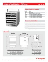
<strong>5100</strong> <strong>Series</strong> <strong>H<strong>or</strong>izontal</strong> <strong>or</strong> <strong>Vertical</strong> <strong>Mounted</strong> <strong>Fan</strong> F<strong>or</strong>ced <strong>Unit</strong> <strong>Heater</strong><br />
3.3 KW THROUGH 50 KW SUSPENDED FAN FORCED UNIT HEATERS AVAILABLE IN 1 OR 3 PHASE FOR ALL STANDARD<br />
VOLTAGES FROM 208V TO 480V THAT CAN BE MOUNTED TO PROVIDE HORIZONTAL OR VERTICAL DISCHARGE.<br />
CONSTRUCTION:<br />
Heavy 18 Gauge welded steel cabinet with powder coated finish and control compartment housing<br />
a master terminal board with a hinged and latched access do<strong>or</strong>, simplifying wiring, installation &<br />
maintenance.<br />
Taskmaster Dimensions<br />
HEATING ELEMENT:<br />
Copper clad steel sheath element<br />
KW DIMENSIONS (inches)<br />
with continuously brazed steel fins<br />
RATING H W D<br />
f<strong>or</strong>med to allow side draw through<br />
air flow.<br />
3.3 - 5.0 17 3/4 14 15/32 6 1/2<br />
OVERHEAT PROTECTION:<br />
All units come equipped with<br />
automatic reset type limit controls<br />
to de-energize the heater should an<br />
over-temperature situation occur.<br />
H<br />
7.5 - 10.0 24 5/16 21 1/2 6 1/2<br />
15.0 - 20.0 28 11/16 21 1/2 6 1/2<br />
25.0 - 50.0 34 29 1/4 10 1/16<br />
<strong>H<strong>or</strong>izontal</strong> Discharge<br />
W<br />
FAN and MOTOR:<br />
Totally enclosed, 1-speed, 1-phase,<br />
permanently lubricated, thermally<br />
protected mot<strong>or</strong>s with unit bearings<br />
on 3 KW - 20 KW models. Totally<br />
enclosed, 2-speed, 1-phase, permanently lubricated, thermally protected mot<strong>or</strong>s with sleeve bearings<br />
on 25 KW - 50 KW models. All mot<strong>or</strong>s mounted with rubber insulat<strong>or</strong>s to minimize vibration &<br />
noise. <strong>Fan</strong> over-ride purges unit of residual heat at shutdown.<br />
D<br />
<strong>Vertical</strong> Discharge<br />
Manufactured in U.S.A.<br />
FIELD INSTALLED OPTIONS:<br />
• In-unit <strong>or</strong> wall mounted<br />
temperature control thermostats<br />
low <strong>or</strong> line voltage.<br />
• Summer fan switch to operate<br />
the fan only.<br />
• Power disconnect switch.<br />
• Heat stratification thermostat.<br />
LOUVER ASSEMBLY:<br />
Louvers are individually adjustable f<strong>or</strong> directional control of air flow up to 15° from straight<br />
h<strong>or</strong>izontal. Optional diffusers available f<strong>or</strong> down flow (vertical discharge) applications.<br />
TEMPERATURE CONTROLS:<br />
Optional low voltage and line voltage thermostats available with an adjustable temperature range of<br />
40°F to 90°F. <strong>Unit</strong>s with model numbers ending in CA1 are fact<strong>or</strong>y wired f<strong>or</strong> low voltage controls.<br />
25 KW through 50 KW units are designed f<strong>or</strong> two stage heating operation.<br />
INSTALLATION:<br />
<strong>Unit</strong> <strong>Heater</strong>s can be mounted f<strong>or</strong> h<strong>or</strong>izontal <strong>or</strong> vertical discharge.<br />
Applications up to 6000 Ft. See UH <strong>Series</strong> above 6000 Ft.<br />
ABS (American Bureau of Shipping) type approved.<br />
Installing the Taskmaster <strong>Series</strong><br />
DETERMINING HEATER REQUIREMENTS<br />
Calculate the heating loads using the NEMA handbook <strong>or</strong> ASHRAE guide. Then determine the quantity and<br />
size of unit heaters to be used. To maintain unif<strong>or</strong>m heat and reduce stratified air, it is recommended that the<br />
total CFM of the units turn the air over approximately 3 times per hour. In instances where a large group of<br />
people are located and n<strong>or</strong>mally in the same area, use a large number of lower KW unit heaters. In warehouse<br />
areas <strong>or</strong> st<strong>or</strong>age rooms where heat distribution and constant temperatures are less imp<strong>or</strong>tant, use fewer heaters<br />
of higher capacity.<br />
HORIZONTAL MOUNT<br />
Small rooms can be heated by one unit heater. Where two walls are exposed, heaters should be mounted as shown<br />
in Figure A. In larger rooms, units should he located so their air streams wipe exposed walls without blowing at<br />
them. <strong>Unit</strong>s should be located so that the air stream of one supp<strong>or</strong>ts that of another thus setting up a circulat<strong>or</strong>y<br />
air movement shown in Figure B. (Distance between units to be approximately 1-1/2 times published air throw.)<br />
<strong>Unit</strong>s should not be mounted h<strong>or</strong>izontally in areas having ceiling heights in excess of 15-18 ft.<br />
VERTICAL MOUNT<br />
<strong>Unit</strong>s should be mounted vertically in high bay areas, <strong>or</strong> where heater location would not interfere with plant<br />
operation <strong>or</strong> traffic, <strong>Heater</strong>s should be situated to provide free air circulation. Size and selection of units should<br />
be based on recommended mounting height. Optional diffusers may best be employed to reduce high air<br />
velocity and at the same time disperse heated air in a unif<strong>or</strong>m pattern. When unit heaters are used to combat<br />
cold air inrush from opened loading dock do<strong>or</strong>s, one <strong>or</strong> m<strong>or</strong>e units should be arranged to blow warm air across<br />
opening (Figure C).<br />
DUAL MOUNTING<br />
Where square footage is large and comf<strong>or</strong>t essential, both h<strong>or</strong>izontal and vertical installations may best serve<br />
your requirements as Figure D demonstrates.<br />
Markel Products Company
<strong>5100</strong> <strong>Series</strong> <strong>H<strong>or</strong>izontal</strong> <strong>or</strong> <strong>Vertical</strong> <strong>Mounted</strong> <strong>Fan</strong> F<strong>or</strong>ced <strong>Unit</strong> <strong>Heater</strong><br />
Diffuser Options<br />
DESCRIPTION<br />
UPC#<br />
686334<br />
MODEL<br />
NUMBER<br />
KW USED<br />
MAX MOUNTING<br />
HEIGHT (ft.)<br />
DIMENSION<br />
A (feet)<br />
DIMENSION<br />
B (feet)<br />
WT. (lbs.)<br />
1<br />
Louver Diffuser (Standard). Louvers can<br />
be individually adjusted f<strong>or</strong> rectangular<br />
coverage over do<strong>or</strong>ways as an air curtain,<br />
<strong>or</strong> to meet rectangular flo<strong>or</strong> pattern heating<br />
requirements.<br />
NA<br />
Standard<br />
3.3-5<br />
7.5-10<br />
25-30<br />
40-50<br />
9<br />
12<br />
18<br />
22<br />
24<br />
20<br />
40<br />
52<br />
75<br />
84<br />
10<br />
22<br />
30<br />
42<br />
47<br />
NA<br />
2<br />
General Distribution (No Diffuser). The<br />
<strong>5100</strong> air chute ventura permits general down<br />
flow air pattern distribution as required at a<br />
higher mounting height.<br />
NA<br />
Not<br />
Required<br />
3.3-5<br />
7.5-10<br />
25-30<br />
40-50<br />
9<br />
12<br />
18<br />
22<br />
24<br />
15<br />
30<br />
40<br />
55<br />
64<br />
NA<br />
NA<br />
3<br />
Anemostat Diffuser (Optional). F<strong>or</strong><br />
applications where draft restriction is<br />
required at lower unit mounting heights.<br />
692687<br />
692687<br />
681186<br />
681186<br />
722070<br />
AD5120<br />
AD5120<br />
AD5150<br />
AD5150<br />
AD5175<br />
3.3-5<br />
7.5-10<br />
25-30<br />
40-50<br />
60-70<br />
10<br />
15<br />
17<br />
20<br />
31<br />
30<br />
38<br />
50<br />
60<br />
-<br />
NA<br />
10<br />
12<br />
37<br />
4<br />
Radial Diffuser (Optional). Individually<br />
adjustable fins permit increased flo<strong>or</strong><br />
coverage at 45° open. Additional throw is<br />
accomplished when fins are 90° vertical.<br />
(Please allow f<strong>or</strong> higher mounting heights.)<br />
692663<br />
692663<br />
692670<br />
692670<br />
722087<br />
RD5120<br />
RD5120<br />
RD5150<br />
RD5150<br />
RD5175<br />
7.5-20<br />
25-50<br />
60-70<br />
45° 90° 45° 90°<br />
10<br />
14<br />
20<br />
18<br />
26<br />
14<br />
21<br />
30<br />
28<br />
36<br />
36<br />
42<br />
62<br />
68<br />
72<br />
30<br />
35<br />
44<br />
54<br />
60<br />
NA<br />
12<br />
14<br />
39<br />
Description 1 Description 2 Description 3 Description 4<br />
Louver Diffuser No Diffuser Anemostat Diffuser Radial Diffuser<br />
Mounting Brackets & Model Designat<strong>or</strong><br />
(*Included with<br />
A<strong>5100</strong> bracket.)<br />
Not actual col<strong>or</strong>s. Red & yellow shading is f<strong>or</strong> diagram clarity only.<br />
MOUNTING BRACKETS<br />
UPC#<br />
686334 MODEL MODEL SIZE WT.<br />
692694 A5105 3.3 KW TO 5.0 KW 9 lbs.<br />
692700 A5120 7.5 KW TO 20.0 KW 13 lbs.<br />
692717 A5150 25.0 KW TO 50.0 KW 16 lbs.<br />
688628 B5105* 3.3 KW TO 20.0 KW 3 lbs.<br />
688635 B5150* 25.0 KW TO 50.0 KW 8 lbs.<br />
692847 V5105 3.3 KW TO 5.0 KW 9 lbs.<br />
692854 V5120 7.5 KW TO 20.0 KW 13 lbs.<br />
692861 V5150 25.0 KW TO 50.0 KW 16 lbs.<br />
DUST SHIELD<br />
692878 DS5105 3.3 KW TO 5.0 KW 3 lbs.<br />
692885 DS5120 7.5 KW TO 20.0 KW 4 lbs.<br />
681223 DS5150 25.0 KW TO 50.0 KW 5 lbs.<br />
FAN GUARD<br />
706544 OFG5101 3.3 KW TO 5.0 KW 3 lbs.<br />
706551 OFG5102 7.5 KW TO 20.0 KW 4 lbs.<br />
706568 OFG5103 25.0 KW TO 50.0 KW 5 lbs.<br />
HOW TO DESIGNATE A MODEL:<br />
HF 2 B 51 10 C A 1<br />
Element Volts<br />
F = 208<br />
H = 240<br />
HF = 240/208<br />
G = 277<br />
P = 480<br />
Phase<br />
1 = 1-Phase<br />
2 = 1 <strong>or</strong> 3-Ph.<br />
3 = 3-Phase<br />
Mot<strong>or</strong> Voltage<br />
F = 208<br />
H = 240<br />
B = 240 / 208<br />
G = 277<br />
P = 480<br />
Model <strong>Series</strong><br />
51<br />
Element KW<br />
Control System<br />
Blank = None<br />
C = Contact<strong>or</strong><br />
Transf<strong>or</strong>mer<br />
Blank = None<br />
A = Included<br />
Control Volts<br />
1 = 24<br />
2 = 120<br />
(with CA option)<br />
* 600 Volt units 5KW - 50KW available on special <strong>or</strong>der, consult fact<strong>or</strong>y f<strong>or</strong> pricing & availability<br />
Markel Products Company
<strong>5100</strong> <strong>Series</strong> <strong>H<strong>or</strong>izontal</strong> <strong>or</strong> <strong>Vertical</strong> <strong>Mounted</strong> <strong>Fan</strong> F<strong>or</strong>ced <strong>Unit</strong> <strong>Heater</strong><br />
UPC#<br />
686334<br />
Standard Taskmaster Models & <strong>Series</strong> Notes<br />
MODEL KW BTU/H VOLTS PH AMPS<br />
CONTROL<br />
VOLTAGE<br />
TEMP<br />
RISE<br />
RECOMMENDED<br />
AIR<br />
THROW CFM MOUNTING HT.<br />
WT.<br />
(LBS.)<br />
<strong>H<strong>or</strong>izontal</strong> <strong>Vertical</strong><br />
645089 F1F5103N 3.3 11.2 208 1 15.9 208<br />
645102 HF1B5103N 3.3/2.5 11.2 / 8.5 240/208 1 13.7 / 11.9 240 / 208<br />
645683 F2F5103N 3.3 11.2 208 1 / 3 11.9 / 6.9 208<br />
645706 HF2B5103N 3.3/2.5 11.2 / 8.5 240/208<br />
1 / 3 13.7 / 11.9<br />
26 o F 12' 400 9' 9' 25<br />
240 / 208<br />
3 7.9 / 6.9<br />
645720 G1G5103N<br />
277 1 11.9 277<br />
3.3 11.2<br />
645126 P3P5103CA1N 480 3 4.0 24<br />
645546 F1F5105N 5.0 17.1 208 1 24.1 208<br />
645560 HF1B5105N 5.0/3.7 17.1 / 12.8 240/208 1 20.9 / 18.1 240 / 208<br />
25<br />
1 / 3 24.1<br />
645140 F2F5105N 5.0 17.1 208<br />
208<br />
3 13.9<br />
40 o F 12' 400 9' 9'<br />
5.0 17.1 240 1 20.8 / 18.1 240<br />
645164 HF2B5105N<br />
3.7 12.8 208 3 12.1 / 10.4 208<br />
27<br />
645843 G1G5105N 5.0 17.1 277 1 18.1 277<br />
645188 P3P5105CA1N 5.0 17.1 480 3 6.1 24<br />
645201 F2F5107CA1L 7.5 25.6 208 1 / 3 36.1 / 20.8<br />
645225 HF2B5107CA1L<br />
7.5 25.6 240 1 / 3 27.1 / 31.3<br />
5.6 19.2 208 1 / 3 31.3 / 27.1<br />
34°F 22' 700 10' 12' 54<br />
645928 G1G5107CA1L 7.5 25.6 277 1 27.1<br />
645249 P3P5107CA1N 7.5 25.6 480 3 9.1<br />
645263 F2F5110CA1L 9.9 33.8 208 1 / 3 47.8 / 27.4<br />
645287 HF2B5110CA1L<br />
10.0 34.1 240 1 / 3 41.2 / 24.0<br />
7.5 25.6 208 1 / 3 36.1 / 20.8<br />
45°F 22' 700 10' 14' 55<br />
645645 G1G5110CA1N 10.0 34.1 277 1 36.1<br />
645300 P3P5110CA1N 10.0 34.1 480 3 12.1<br />
645324 F3F5115CA1L 15.0 51.2 208 3 41.7<br />
645348 HF3B5115CA1L 15.0/11.2 51.2 / 38.4 240/208 3 36.1 / 31.3 43°F 32' 1100 11' 20' 64<br />
645362 P3P5115CA1N 15.0 51.2 480 3 18.1<br />
645386 HF3B5120CA1L 19.7/14.8 67.2 / 50.5 240/208 3 47.8 / 41.1 24<br />
645409 P3P5120CA1N 20.0 68.3 480 3 24.1<br />
57°F 32' 1100 12' 18' 65<br />
645881 F3F5125CA1L 25.0 85.3 208 3 69.5<br />
645942 HF3B5125CA1L 25.0/18.7 85.3 / 64.0 240/208 3 60.2 / 52.1 40/44°F 45' 2000/1800 12' 22' 120<br />
645980 P3P5125CA1N 25.0 85.3 480 3 30.1<br />
645423 F3F5130CA1L 30.0 102.4 208 3 83.4<br />
645447 HF3B5130CA1L 30.0/22.5 102.4 / 76.8 240/208 3 72.3 / 62.5 47/53°F 40' 2000/1800 12' 20' 120<br />
645461 P3P5130CA1N 30.0 102.4 480 3 36.2<br />
644044 F3F5140CA1L 40.0 136.5 208 3 111.2<br />
644068 HF3B5140CA1L 40.0/30.0 136.5/102.4 240/208 3 96.4 / 83.4 40/45°F 55' 3100/2800 15' 24' 120<br />
644082 P3P5140CA1N 39.0 133.1 480 3 47.0<br />
645485 F3F5150CA1L 49.6 169.3 208 3 139.0<br />
645508 HF3B5150CA1L 50.0/37.5 170.6/128.0 240/208 3 120.5/104.3 51/56°F 50' 3100/2800 15' 22' 120<br />
645522 P3P5150CA1N 50.0 170.6 480 3 60.3<br />
• F<strong>or</strong> 24V control add “CA1” suffix. • F<strong>or</strong> 120V control add “CA2” suffix. • F<strong>or</strong> other voltages consult fact<strong>or</strong>y.<br />
NOTES:<br />
• 25-50KW models are wired f<strong>or</strong> single <strong>or</strong> two stage heating and have two speed mot<strong>or</strong>s.<br />
• Air delivery and mot<strong>or</strong> data on dual voltage units reflect higher voltage.<br />
• 600 Volt models available in 5 KW through 30 KW. Contact fact<strong>or</strong>y f<strong>or</strong> delivery.<br />
• Supply wire on 40 and 50 KW models should have rated insulation of 75 o C minimum.<br />
• Use T5122 f<strong>or</strong> two stage control.<br />
• Use TW123 f<strong>or</strong> two stage control.<br />
• Use TFS5102 f<strong>or</strong> two stage control.<br />
• Wall thermostat must be used when built-in stratification thermostat is required.<br />
Markel Products Company
<strong>5100</strong> <strong>Series</strong> <strong>H<strong>or</strong>izontal</strong> <strong>or</strong> <strong>Vertical</strong> <strong>Mounted</strong> <strong>Fan</strong> F<strong>or</strong>ced <strong>Unit</strong> <strong>Heater</strong><br />
MODEL<br />
NUMBER<br />
F1F5103N<br />
HF1B5103N<br />
Recommended Control Options, Control Access<strong>or</strong>y Options, & Control Access<strong>or</strong>ies<br />
DISCONNECT<br />
SWITCH<br />
1 Ø 3 Ø IN-BUILT<br />
THERMOSTAT<br />
DCS 202 NA T<strong>5100</strong> ET5SS<br />
CONTROL ACCESSORY OPTIONS - FIELD INSTALLED IN HEATER<br />
UPC#<br />
MODEL<br />
DESCRIPTION<br />
686334<br />
POWER DISCONNECT SWITCH<br />
717151 DCS202/<strong>5100</strong> 2 POLE; 20 AMP; 120-277 V.A.C.<br />
717168 DCS403/<strong>5100</strong> 3 POLE; 40 AMP; 120-600 V.A.C.<br />
717175 DCS603/<strong>5100</strong> 3 POLE; 60 AMP; 120-600 V.A.C.<br />
717182 DCS1003/<strong>5100</strong> 3 POLE; 100 AMP; 120-600 V.A.C.<br />
LINE VOLTAGE THERMOSTAT (45 - 90 o F)<br />
692779 T<strong>5100</strong> SPST; LINE DUTY 25 AMP 120-277V<br />
692786 T5102 DPST; LINE DUTY 25 AMP 120-277V<br />
LOW VOLTAGE THERMOSTAT (ALL CA1 MODELS) (45 - 90 o F)<br />
692779 T<strong>5100</strong> SPST; LOW VOLT/PILOT DUTY; 125VA ; (3.3-20 KW UNITS)<br />
692793 T5122 2-STAGE; LOW VOLT; 125VA; (25-50 KW UNITS)<br />
STRATIFICATION THERMOSTAT<br />
692809 TC5102 SPST; LOW VOLT/PILOT DUTY (W/RELAY) ; 70-130 O<br />
692816 TC5103 SPST; LINE DUTY; AMP 120-240V; 70-130 O<br />
SUMMER FAN SWITCH<br />
692823 FS5101 SPST; LINE VOLT ;120-277V<br />
692830 FS5102 SPST; LINE VOLT ; 480-600V<br />
SUMMER FAN SWITCH<br />
WALL<br />
MOUNTED IN-BUILT WALL<br />
MOUNTED<br />
LINE VOLTAGE THERMOSTAT<br />
691086 **TW1510 SPST; 25 AMP 120-277V 50-90 o<br />
691093 *TW1512 DPST; 25 AMP 120-277V 50-90 o<br />
LOW VOLTAGE THERMOSTAT (ALL CA1 MODELS)<br />
260008 A6176 SPST; (3.3 - 20 KW UNITS) 50-90 O<br />
691116 TW123 2STAGE; (25 - 50 KW UNITS) 40-90 O<br />
STRATIFCATION THERMOSTAT<br />
691109 TC1602 LINE VOLT 120-277V 70-140 O<br />
SUMMER FAN SWITCH<br />
692625 FSW5111 SPST; LINE VOLT 120-277V<br />
692632 FSW5112 SPST; LOW VOLT (W/RELAY)<br />
LOW VOLTAGE T'STAT & SUMMER FAN SWITCH(W/RELAY) (CA1 MODELS)<br />
692649 TFS5101 SPST; LOW VOLT 50-90 O<br />
692502 TFS5102 2 STAGE; LOW VOLT 50-90 O<br />
**Any SPST thermostat of sufficient amperage may be substituted.<br />
*Use DPST thermostat f<strong>or</strong> 3-phase line voltage control in non “C” models.<br />
Markel Products Company<br />
THERMOSTAT &<br />
SUMMER FAN<br />
SWITCH<br />
WALL MOUNTED<br />
STRATIFICATION<br />
THERMOSTAT<br />
WALL<br />
IN-BUILT<br />
MOUNTED<br />
F2F5103N<br />
NA DCS 403 T5102 TW 1512 FS5101 FSW5111 NA<br />
TC5103<br />
TC1602<br />
HF2B5103N<br />
DCS 202 NA T<strong>5100</strong> ET 5SS<br />
NA DCS 403 T5102 TW 1512<br />
G1G5103N DCS 202 NA<br />
ET5SS<br />
NA<br />
P3P5103CA1N NA DCS 403 A6176 FS5102 FSW5112 TFS5101 TC5102 NA<br />
F1F5105N<br />
T<strong>5100</strong> S2025<br />
HF1B5105N DCS 403 NA<br />
ET5SS<br />
F2F5105N<br />
S2025<br />
TC5103<br />
NA DCS 403 T5102 TW 1512 FS5101 FSW5111 NA<br />
TC1602<br />
HF2B5105N<br />
DCS 403 NA T<strong>5100</strong> ET5SS<br />
NA DCS 403 T5102 TW 1512<br />
G1G5105N DCS 202 NA<br />
S2025<br />
NA<br />
P3P5105CA1N NA DCS 403<br />
FS5102 FSW5112<br />
TC5102 NA<br />
F2F5107CA1L DCS 403 NA NA DCS 403<br />
TC5103<br />
DCS 403<br />
FS5101 FSW5111<br />
TC1602<br />
HF2B5107CA1L NA<br />
NA DCS 403<br />
G1G5107CA1L DCS 403 NA NA<br />
P3P5107CA1L NA DCS 403 FS5102 FSW5112 TC5102 NA<br />
F2F5110CA1L DCS 603 NA A6176<br />
NA DCS 403 T<strong>5100</strong><br />
OR<br />
TFS5101 TC5103<br />
DCS 603<br />
FS5101 FSW5111<br />
TC1602<br />
HF2B5110CA1L NA<br />
TW123<br />
NA DCS 403<br />
G1G5110CA1N DCS 403 NA NA<br />
P3P5110CA1N<br />
DCS 403 FS5102 FSW5112<br />
NA<br />
F3F5115CA1L DCS 603<br />
HF3B5115CA1L DCS 403<br />
FS5101 FSW5111 TC1602<br />
P3P5115CA1L DCS 403 FS5102 FSW5112 NA<br />
HF3B5120CA1L DCS 603 FS5101 FSW5111 TC1602<br />
P3P5120CA1N DCS 403 FS5102 FSW5112 NA<br />
F3F5125CA1L<br />
HF3B5125CA1L<br />
DCS 1003<br />
FS5101 FSW5111<br />
TC1602<br />
P3P5125CA1N DCS 403 FS5102 FSW5112 NA<br />
NA<br />
TC5103<br />
F3F5130CA1L DCS 1003<br />
FS5101 FSW5111 TC1602<br />
HF3B5130CA1L DCS 1003<br />
A6176<br />
P3P5130CA1N DCS 403 FS5102 FSW5112 NA<br />
T<strong>5100</strong> OR<br />
TFS5101<br />
F3F5140CA1L<br />
NA<br />
TW123 FS5101 FSW5111 TC1602<br />
HF3B5140CA1L DCS 403<br />
P3P5140CA1N DCS 603 FS5102 FSW5112 NA<br />
F3F5150CA1L<br />
HF3B5150CA1L<br />
NA FS5101 FSW5111 TC1602<br />
P3P5150CA1N DCS 1003 FS5102 FSW5112 NA<br />
CONTROL ACCESSORIES - REMOTE WALL MOUNTED<br />
UPC#<br />
MODEL DESCRIPTION<br />
686334
<strong>5100</strong> <strong>Series</strong> 60 KW - 100 KW Suspended <strong>Fan</strong> F<strong>or</strong>ced <strong>Unit</strong> <strong>Heater</strong><br />
Manufactured in U.S.A.<br />
Features & Specifications<br />
CONSTRUCTION:<br />
Heavy Gauge steel cabinet with powder coated finish and control compartment<br />
housing a master terminal board. The control compartment allows f<strong>or</strong> access<br />
through a hinged and latched do<strong>or</strong>, simplifying wiring, installation, and<br />
maintenance.<br />
HEATING ELEMENT:<br />
The heating element is a copper clad steel sheath element with continuously brazed steel<br />
fins f<strong>or</strong>med to allow side draw through air flow.<br />
OVERHEAT PROTECTION:<br />
All units come equipped with manual reset type limit controls to de-energize the heater<br />
should an over-temperature situation occur.<br />
FAN & MOTOR:<br />
Single speed, single phase permanently lubricated, thermally protected mot<strong>or</strong>s with ball<br />
bearings. The fan override purges the unit of residual heat at shutdown.<br />
FIELD INSTALLED OPTIONS:<br />
Summer fan switch to operate the fan only, and a heat stratification thermostat f<strong>or</strong> high<br />
bay areas.<br />
HEATER STAGING:<br />
60 KW and 70 KW are three stage; 80 KW, 90 KW, & 100 KW are four stage.<br />
SC<strong>5100</strong> FACTORY INSTALLED ELECTRONIC STEP CONTROLLER:<br />
The optional fact<strong>or</strong>y installed step controller is a first on last off sequencer that will cycle<br />
the unit heater stages through an optional wall thermostat. Additionally, the step controller<br />
can be controlled by any building management system with 4 to 20 MA <strong>or</strong> 0 - 10 VDC<br />
field supplied control signal.<br />
Optional Fact<strong>or</strong>y Installed Electronic Step Controller<br />
C<br />
C1 C2 C3<br />
S<br />
VC4<br />
COM<br />
3 OR 4 STAGE<br />
STEP CONTROL<br />
POWER<br />
1 2 3<br />
1<br />
2<br />
3<br />
ON<br />
1 2 3 4<br />
INPUT<br />
ON<br />
1 2 3 4 5 6<br />
CONTROL<br />
90<br />
60<br />
120<br />
30 VR1<br />
DELAY(s)<br />
150<br />
200<br />
VR2<br />
RATIO(%)<br />
100<br />
TEST<br />
REV.1<br />
JUNE 99<br />
001-0102<br />
0-10VDC-CONTROL<br />
OR C1025 WALL<br />
THERMOSTAT<br />
+ 4MA-O%HEAT<br />
_<br />
20MA-100%HEAT<br />
Dimensions<br />
Wall / Ceiling Bracket<br />
Markel Products Company<br />
Dimensions (Inches)<br />
Weight<br />
KW H W D (lbs.)<br />
60-70 35 1/2 30 1/2 14 1/2 141<br />
80-100 39 1/2 37 5/8 18 1/2 202<br />
Mounting Brackets and Access<strong>or</strong>ies<br />
Mounting Brackets<br />
UPC Model <strong>Heater</strong> KW Description<br />
7220002 A5175 60 To 70<br />
7220102 A51100 80 to 100<br />
Wall/Ceiling Bracket<br />
7220302 B5175 60 to 70<br />
7220402 B51100 80 to 100<br />
<strong>Heater</strong> Bracket<br />
7220202 V51100 60 to 100 <strong>Vertical</strong> Bracket<br />
7220502 DS5175 60 to 70<br />
7220602 DS51100 80 to 100<br />
Dust Shield<br />
7220902 OFG 5175 60 to 70<br />
7221002 OFG 51100 80 to 100<br />
<strong>Fan</strong> Guard
<strong>5100</strong> <strong>Series</strong> 60 KW - 100 KW Suspended <strong>Fan</strong> F<strong>or</strong>ced <strong>Unit</strong> <strong>Heater</strong><br />
Electrical Data<br />
UPC#<br />
686334<br />
Catalog Number<br />
KW<br />
BTU/HR<br />
(x 1000)<br />
Voltage Phase Control Voltage Amps / Phase<br />
Branch Circuit<br />
Protection Size<br />
721349 F3F5160CA1 60 204.7 208<br />
166.7 225<br />
721356 HF3B5160CA1 60/45 204.7/153.6 240/208 3 24 144.6/125 200/175<br />
721363 P3P5160CA1 60 204.7 480 72.3 100<br />
721424 F3F5170CA1 70 238.9 208<br />
194.4 250<br />
721431 HF3B5170CA1 70/52.5 238.9/179.2 240/208 3 24 168.7/145.8 225/200<br />
721448 P3P5170CA1 70 238.9 480 84.3 110<br />
721707 HF3B5180CA1 80/60 273/204.7 240/208<br />
192.8/166.7 250/225<br />
3 24<br />
721714 P3P5180CA1 80 273 480 96.3 125<br />
721769 HF3B5190CA1 90/67.5 307.1/230.4 240/208<br />
216.9/187.5 300/250<br />
3 24<br />
721776 P3P5190CA1 90 307.1 480 108.4 150<br />
721820 HF3B51100CA1 100/75 341.3/256 240/208<br />
241/208.3 350/300<br />
3 24<br />
721837 P3P51100CA1 100 341.3 480 120.4 175<br />
Air Delivery Data<br />
UPC#<br />
686334<br />
Catalog Number CFM at Outlet FPM at Outlet<br />
721349 F3F5160CA1<br />
Temp Rise<br />
°F<br />
721356 HF3B5160CA1 60/45<br />
721363 P3P5160CA1 60<br />
3400 1485<br />
721424 F3F5170CA1 70<br />
721431 HF3B5170CA1 70/53<br />
721448 P3P5170CA1 70<br />
721707 HF3B5180CA1<br />
721769 HF3B5190CA1 61/46<br />
5000 1529<br />
721776 P3P5190CA1 61<br />
60<br />
55/41<br />
721714 P3P5180CA1 55<br />
721820 HF3B51100CA1 68/51<br />
721837 P3P51100CA1 68<br />
HP Mot<strong>or</strong> RPM Air Throw<br />
Max Mounting<br />
<strong>H<strong>or</strong>izontal</strong> <strong>Vertical</strong><br />
1/3 1100 50’ 18’ 31’<br />
3/4 1100 65’ 22’ 40’<br />
Recommended Control Options<br />
UPC#<br />
686334<br />
Catalog Number Step Controller Thermostat<br />
Summer <strong>Fan</strong> Switch<br />
Stratification Thermostat<br />
Wall Built-In Wall Built-In<br />
721349 F3F5160CA1<br />
FS5101<br />
721356 HF3B5160CA1 FS5101<br />
721363 P3P5160CA1 FS5102<br />
721424 F3F5170CA1 FS5101<br />
721431 HF3B5170CA1 FS5101<br />
721448 P3P5170CA1 FS5102<br />
SC<strong>5100</strong> C1025 FSW5112<br />
721707 HF3B5180CA1 FS5101<br />
721714 P3P5180CA1 FS5102<br />
721769 HF3B5190CA1 FS5101<br />
721776 P3P5190CA1 FS5102<br />
721820 HF3B51100CA1 FS5101<br />
721837 P3P51100CA1 FS5102<br />
Markel Products Company<br />
TFS5101<br />
TC5102
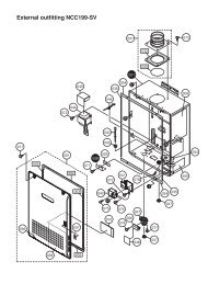
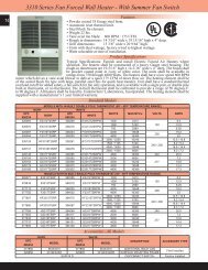
2600 <strong>Series</strong> Downflow <strong>Unit</strong> <strong>Heater</strong><br />
General Description & Diffuser Inf<strong>or</strong>mation<br />
CONSTRUCTION:<br />
• 16 Gauge steel cabinet with epoxy powder coated finish and control compartment with a hinged and<br />
latched access do<strong>or</strong>.<br />
• OSHA guards standard with all models.<br />
HEATING ELEMENT:<br />
• C<strong>or</strong>rosion resistant element with steel sheath and steel spiral fins.<br />
OVERHEAT PROTECTION:<br />
• All units come equipped with manual reset limit controls to de-energize the heater should an<br />
over-temperature situation occur.<br />
FAN and MOTOR:<br />
• Totally enclosed, 1 speed, 1 phase permanently lubricated, thermally protected<br />
mot<strong>or</strong>s with unit bearings on 3KW - 20KW models. Totally enclosed, 2 speed,<br />
1 phase permanently lubricated, thermally protected mot<strong>or</strong>s with sleeve bearings<br />
on 24KW - 50KW models.<br />
• Axial flow fan blade - 1570 RPM max.<br />
• All models equipped with fan purge which allows fan to operate after<br />
elements are de-energized to purge residual heat.<br />
TEMPERATURE CONTROLS:<br />
• 208V, 240V, 277V and 480V units have In-Built 24 Volt transf<strong>or</strong>mer f<strong>or</strong> low<br />
voltage remote thermostat application.<br />
• 600V units have In-Built 240V control on 5-20 KW models, 25-50 KW models have<br />
24V control.<br />
• 25 KW - 50 KW models may operate as 2 stage heaters if 2 stage remote thermostat is used.<br />
DISCONNECT SWITCH:<br />
• All models equipped with In-Built disconnect except F3F2640, F3F2650 and H3H2650.<br />
INSTALLATION:<br />
• <strong>Unit</strong> can be mounted using optional mounting bracket <strong>or</strong> field constructed angle iron bracket.<br />
• Not recommended f<strong>or</strong> mounting with threaded rod <strong>or</strong> chain.<br />
Manufactured in U.S.A.<br />
2600 <strong>Series</strong> shown with<br />
standard wire guard.<br />
Diffusers are field installed.<br />
Standard <strong>Heater</strong><br />
Radial Louvered Cone Diffuser<br />
Linear Louvered Diffuser<br />
Anemostat Diffuser<br />
Dimensions**<br />
KW B A<br />
5-20 20 1/2” 15”<br />
25-50 27” 21 1/2”<br />
Diffuser Descriptions<br />
A<br />
B<br />
F<strong>or</strong> general distribution.<br />
Choice of other diffusers<br />
may be added after<br />
installation if required.<br />
O.S.H.A guard f<strong>or</strong><br />
fan blade D1604 f<strong>or</strong><br />
2605-2620, & D1614 f<strong>or</strong><br />
2625-2650 Do not use<br />
with other diffusers.<br />
B<br />
A<br />
MODEL KW DIM: A DIM: B MODEL KW DIM: A DIM: B MODEL KW DIM: A DIM: B<br />
D1600 5-20 6 1/2" 14 1/4" D1602 5-20 6" 16 1/4" D1603 5-20 7" 19 1/4"<br />
D1610 25-50 11 1/2" 24 3/4" D1612 25-50 6" 22 1/4" D1613 25-50 9 3/4" 29 3/4"<br />
With vanes vertical, straightens air f<strong>or</strong> higher<br />
mounting. Closed position f<strong>or</strong> broad h<strong>or</strong>izontal<br />
coverage. Adjustable f<strong>or</strong> intermediate<br />
requirements.<br />
B<br />
A<br />
B<br />
Aff<strong>or</strong>ds m<strong>or</strong>e precise directional<br />
throw where heaters cannot be<br />
mounted directly over area to be<br />
heated <strong>or</strong> f<strong>or</strong> heating long narrow<br />
areas.<br />
B<br />
A<br />
B<br />
Blends room air with<br />
heated air f<strong>or</strong> widespread<br />
distribution without<br />
excessive drafts.<br />
D'<br />
D'<br />
W'<br />
L'<br />
D'<br />
MODEL<br />
2605<br />
2607<br />
2610<br />
2615<br />
2620<br />
2625<br />
2630<br />
2640<br />
2650<br />
MAX<br />
MOUNTING<br />
HEIGHT*<br />
10<br />
10<br />
22<br />
20<br />
18<br />
32<br />
30<br />
26<br />
24<br />
D<br />
(ft.)<br />
25<br />
25<br />
40<br />
44<br />
48<br />
48<br />
60<br />
64<br />
68<br />
VERTICAL<br />
MAX<br />
MOUNTING<br />
HEIGHT<br />
15<br />
15<br />
26<br />
24<br />
22<br />
38<br />
36<br />
32<br />
28<br />
D<br />
(ft.)<br />
25<br />
25<br />
36<br />
38<br />
40<br />
42<br />
50<br />
50<br />
50<br />
45 DEGREES OPEN<br />
MAX<br />
MOUNTING<br />
HEIGHT<br />
8<br />
8<br />
15<br />
14<br />
13<br />
24<br />
22<br />
20<br />
18<br />
D<br />
(ft.)<br />
30<br />
30<br />
44<br />
46<br />
50<br />
70<br />
74<br />
78<br />
82<br />
MAX<br />
MOUNTING<br />
HEIGHT<br />
10<br />
10<br />
22<br />
20<br />
18<br />
34<br />
32<br />
30<br />
28<br />
*Minimum mounting height 6 feet.<br />
**Dimensions are f<strong>or</strong> all heater models without a diffuser option. Adding a diffuser will change the vertical (”A”) dimension of heater.<br />
All mounting distances are in feet. All diagrams show optional mounting bracket.<br />
W<br />
(ft.)<br />
10<br />
10<br />
14<br />
14<br />
15<br />
30<br />
34<br />
36<br />
40<br />
Markel Products Company<br />
L<br />
(ft.)<br />
40<br />
40<br />
54<br />
60<br />
66<br />
80<br />
80<br />
90<br />
100<br />
MAX<br />
MOUNTING<br />
HEIGHT<br />
9<br />
9<br />
20<br />
18<br />
16<br />
30<br />
28<br />
26<br />
24<br />
D<br />
(ft.)<br />
25<br />
25<br />
38<br />
40<br />
42<br />
60<br />
64<br />
67<br />
70
2600 <strong>Series</strong> Downflow <strong>Unit</strong> <strong>Heater</strong><br />
Standard Models<br />
UPC#<br />
686334<br />
MODEL KW BTU’s VOLTS PH AMPS<br />
CONTROL<br />
VOLTS<br />
TEMP<br />
RISE O F<br />
CFM<br />
WT<br />
(lbs.)<br />
715751 F1F2605CA1<br />
208<br />
24.03<br />
715768 H1H2605CA1 240 1 20.83<br />
715775 G1G2605CA1 277 18.05<br />
715782 F3F2605CA1 5 17065 208<br />
13.89<br />
24<br />
715799 H3H2605CA1 240 12.04<br />
3<br />
715805 P3P2605CA1 480 6.02<br />
715812 U3H2605CA4 600 4.81 240<br />
715829 F1F2607CA1<br />
208<br />
36.05<br />
715836 H1H2607CA1 240 1 31.25<br />
715843 G1G2607CA1 277 27.07<br />
715850 F3F2607CA1 7.5 25598 208<br />
20.84<br />
24<br />
715867 H3H2607CA1 240 18.06<br />
3<br />
715874 P3P2607CA1 480 9.03<br />
715881 U3H2607CA4 600 7.22 240<br />
715898 F1F2610CA1<br />
208<br />
48.07<br />
715904 H1H2610CA1 240 1 41.66<br />
715911 G1G2610CA1 277 36.1<br />
715928 F3F2610CA1 10 34130 208<br />
27.79<br />
24<br />
715935 H3H2610CA1 240 24.08<br />
715942 P3P2610CA1 480 12.04<br />
715959 U3H2610CA4 600 9.63 240<br />
715966 F3F2615CA1<br />
208 41.68<br />
715973 H3H2615CA1 240 36.12 24<br />
15 51195<br />
715980 P3P2615CA1 480 18.06<br />
715997 U3H2615CA4 600 14.45 240<br />
716000 H3H2620CA1 19.4<br />
240 48.16<br />
24<br />
716017 P3P2620CA1<br />
68260 480 24.08<br />
20<br />
717502 U3H2620CA4 600 19.26 240<br />
717519 F3F2625CA1<br />
208 69.48<br />
717526 H3H2625CA1 240 60.21<br />
25 85325<br />
717533 P3P2625CA1 480 3 30.1<br />
717540 U3U2625CA1 600 24.08<br />
717557 F3F2630CA1<br />
208 83.37<br />
717564 H3H2630CA1 240 72.25<br />
30 102390<br />
717571 P3P2630CA1 480 36.12<br />
717588 U3U2630CA1 600 28.9<br />
717595 F3F2640CA1<br />
208 111.17<br />
24<br />
717601 H3H2640CA1 240 96.33<br />
40 136520<br />
717618 P3P2640CA1 480 48.16<br />
717625 U3U2640CA1 600 38.53<br />
717632 F3F2650CA1<br />
208 138.96<br />
717649 H3H2650CA1 240 120.42<br />
50 170650<br />
717656 P3P2650CA1 480 60.21<br />
717663 U3U2650CA1 600 48.16<br />
Markel Products Company<br />
34 490 75<br />
45 560 75<br />
26 1200 75<br />
39 1200 75<br />
52 1200 75<br />
24 3300 175<br />
29 3300 175<br />
38 3300 175<br />
48 3300 175
2600 <strong>Series</strong> Downflow <strong>Unit</strong> <strong>Heater</strong><br />
Field Installed Access<strong>or</strong>ies<br />
UPC#<br />
686334<br />
MODEL<br />
DESCRIPTION<br />
UPC#<br />
686334<br />
MODEL<br />
DESCRIPTION<br />
692632 FSW5112 Summer <strong>Fan</strong> Switch<br />
692809 TC5102 Wall <strong>Mounted</strong> Stratification Thermostat<br />
717755 A1600 Ceiling Mount Bracket 5-20 KW Models<br />
717762 A1601 Ceiling Mount Bracket 25-50 KW Models<br />
717793 D1602 Linear Louvered Diffuser 5-20 KW Models<br />
717809 D1612 Linear Louvered Diffuser 25-50 KW Models<br />
717816 D1600 Radial Louvered Cone Diffuser 5-20 KW Models<br />
717823 D1610 Radial Louvered Cone Diffuser 25-50 KW Models<br />
717830 D1603 Anemostat Diffuser 5-20 KW Models<br />
717847 D1613 Anemostat Diffuser 25-50 KW Models<br />
Product Specifications<br />
SPECIFICATIONS: The contract<strong>or</strong> shall furnish and install the 2600 <strong>Series</strong> electric vertical discharge unit<br />
heaters of the size, capacity and voltage specified. <strong>Heater</strong>s shall be installed acc<strong>or</strong>ding to the manufacturer’s<br />
recommendations and applicable national and local codes.<br />
ELEMENTS: Elements shall consist of Nickel Chromium alloy resistance wire embedded and completely<br />
surrounded in Magnesium Oxide, enclosed and swagged into c<strong>or</strong>rosion resistant sheaths. C<strong>or</strong>rosion resistant<br />
steel fins shall be permanently attached to the sheaths to provide maximum heat transfer to the air stream.<br />
MOTORS: Mot<strong>or</strong>s shall be single phase, resilient mounted, totally enclosed, industrial rated with an<br />
automatic reset thermal overload protective device. Mot<strong>or</strong>s on heaters up to 20 KW capacity shall be<br />
permanently lubricated shaded pole type. Over 20 KW, mot<strong>or</strong>s shall be permanent split capacit<strong>or</strong> type.<br />
Mot<strong>or</strong>s shall be mounted out of the main air stream in such a manner as to allow ambient air to be drawn<br />
over the mot<strong>or</strong> to reduce mot<strong>or</strong> temperature. Mot<strong>or</strong> shall be separately removable from beneath the heater<br />
without removing the entire heater from mounting bracket.<br />
FAN BLADES: <strong>Fan</strong> blades shall be heavy-duty individually balanced axial flow type. <strong>Fan</strong> speed shall not<br />
exceed 1570 RPM.<br />
THERMAL OVERLOAD PROTECTION: All heaters shall be equipped with a manual reset thermal<br />
cutout which disconnects elements and mot<strong>or</strong> in the event n<strong>or</strong>mal operating temperatures are exceeded.<br />
WIRING: <strong>Heater</strong>s shall be designed f<strong>or</strong> a single supply circuit with elements, mot<strong>or</strong> and control circuits<br />
subdivided and fused to conf<strong>or</strong>m with the latest National Electric Code and OSHA requirements. All three<br />
phase heaters shall have balanced phases.<br />
CONTROLS: <strong>Heater</strong>s shall be controlled by a low voltage wall mounted thermostat. All heaters 25 KW<br />
and larger shall be wired f<strong>or</strong> 2 stage operation. 5 KW through 20 KW units are single stage. All heaters shall<br />
be equipped with a fan safety device that causes fan to operate after elements are de-energized to purge unit<br />
of residual heat.<br />
Markel Products Company
5600 <strong>Series</strong> Multiple Wattage <strong>Fan</strong> F<strong>or</strong>ced <strong>Unit</strong> <strong>Heater</strong><br />
Product Specifications<br />
CASING: Fabricated of die f<strong>or</strong>med,<br />
heavy Gauge steel and finished with two<br />
tone, brown and beige, durable powder<br />
coated paint. Supply air is drawn through<br />
the rear heavy duty expanded steel inlet<br />
grill. Heated air is discharged through<br />
front adjustable louvers, which are spring<br />
loaded f<strong>or</strong> individual adjustment.<br />
ELEMENT: Heavy-duty block fin<br />
element design. The multiple tap electric<br />
connection design allows field conversion<br />
to eight wattage settings at 208/240-Volt<br />
single phase <strong>or</strong> 240/480 Volt, 3 phase.<br />
<strong>Unit</strong>s are available on special <strong>or</strong>der with a<br />
specific wattage/voltage setting.<br />
MOTOR: Mot<strong>or</strong> shall be totally enclosed,<br />
Rear view<br />
permanently lubricated, all angle industrial<br />
rated with thermal overload protection.<br />
WIRING: Wiring to terminal block<br />
adjacent to incoming knockout in Front view<br />
acc<strong>or</strong>dance with NEC and local codes.<br />
Manufactured in U.S.A.<br />
THERMAL OVERLOAD: All heaters<br />
shall be equipped with an automatic reset thermal cutout to<br />
shut down the element and mot<strong>or</strong> circuits if unsafe operating<br />
temperatures are exceeded.<br />
CONTROLS: The heater shall have a heavy-duty hydraulic thermostat fact<strong>or</strong>y installed and wired. All controls and<br />
wiring shall be in a large wiring compartment with hinged do<strong>or</strong> f<strong>or</strong> easy access. An optional disconnect switch shall<br />
be available f<strong>or</strong> field installation.<br />
MOUNTING: <strong>Heater</strong>s are standard with a three position-mounting bracket f<strong>or</strong> wall, ceiling <strong>or</strong> w<strong>or</strong>kbench. <strong>Heater</strong>s<br />
can be mounted f<strong>or</strong> h<strong>or</strong>izontal <strong>or</strong> vertical discharge. Note: Minimum mounting height is 6 feet, and minimum distance<br />
from side of heater to nearest wall is 6 inches. Note: Approved f<strong>or</strong> residential applications.<br />
Product Dimensions<br />
A B C D E F G<br />
14” 12-11/16” 14” 1-9/16” 1-9/16” 9” 2-3/4”<br />
UPC<br />
686334<br />
707282 HF5605T<br />
707299 H3H5605T<br />
Standard Models<br />
MODEL WATTS BTU's VOLTS PHASE AMPS TEMP RISE<br />
5000 17065<br />
4165 14215 17 48 o F<br />
240 1<br />
3332 11365 14 38 o F<br />
Markel Products Company<br />
21 57 o F<br />
2500 8533 10 29 o F<br />
3750 12798<br />
18 43 o F<br />
AIR<br />
THROW<br />
CFM WT. (LBS.)<br />
16' 275 32<br />
3123 10659 15 36 o F<br />
208 1<br />
2500 8553 12 29 o F 16' 275<br />
1874 6396 9 21 o F<br />
3750 12799 208 3 10.4 57 o F 16’ 375 32<br />
5000 17065 240 3 12 57 o F 16' 275 32<br />
707305 P3P5605T 5000 17065 480 3 6 57 o F 16' 275 32<br />
707367 DCS-MT303 Optional Field Installed Disconnect Switch, 30 Amp @ 600Volts<br />
F<strong>or</strong> 24V control on single phase models delete "T" suffix<br />
32
Up Flow<br />
A<br />
W<br />
B<br />
C<br />
A<br />
D D D<br />
A<br />
C<br />
B<br />
A<br />
D D D<br />
Y W Y Y Z X Z X X<br />
Semi<br />
Recessed<br />
Completely<br />
Recessed<br />
Down Flow<br />
Semi<br />
Recessed<br />
Completely<br />
Recessed<br />
A B C D A D D<br />
W Z W X Y Z Y X W Z Y X Y X<br />
Ceiling <strong>Mounted</strong><br />
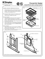
6300 <strong>Series</strong> Multiple Angle Cabinet <strong>Unit</strong> <strong>Heater</strong><br />
Product Specifications<br />
TEMPERATURE CONTROL: Integral fact<strong>or</strong>y installed thermostat shall be tamper resistant, linear capillary type.<br />
Mounting Configurations<br />
Semi<br />
Recessed<br />
Completely<br />
Recessed<br />
KEY: W = 6” minimum, X = 12” minimum, Y = 0” <strong>or</strong> greater, Z = 24” minimum<br />
The electric cabinet unit heater shall be be UL listed, designed f<strong>or</strong><br />
mounting in any position, fully recessed, semi-recessed <strong>or</strong> surface<br />
mounted. All capacities, voltages, physical sizes, grille arrangements<br />
and options shall be as specified on the plans. All units must be field<br />
convertible to the following:<br />
1. F<strong>or</strong> control by a field supplied remote thermostat.<br />
2. Load management control with an external dry switch.<br />
When closed unit operates under control of either<br />
the internal <strong>or</strong> the external thermostat. When open, unit<br />
turns off.<br />
3. Any grille arrangement.<br />
CABINET: The cabinet shall be constructed of heavy duty 16<br />
Gauge Zinc coated steel. The heater shall have a removable front<br />
Manufactured in U.S.A.<br />
do<strong>or</strong> f<strong>or</strong> easy access to the control panel, elements, mot<strong>or</strong>-blower<br />
assembly, filters and all internal components. The grill configuration must be easily field convertible to any air flow configuration<br />
(by removal of no m<strong>or</strong>e than four fasteners). The cabinet shall have a textured finish of two coats of powder coat epoxy and be<br />
suitable f<strong>or</strong> use with optional kick space base.<br />
HEATING ELEMENTS: The heating elements shall be warranted f<strong>or</strong> 1 year and shall be non-glowing design consisting<br />
of special high temperature resistance wire enclosed in an incoloy sheath to which steel fins are furnace brazed. The heating<br />
elements shall be located directly in front of the blower discharge air f<strong>or</strong> unif<strong>or</strong>m heating. They shall be mounted with a single<br />
anch<strong>or</strong> at one end to minimize effects of thermal expansion and contraction.<br />
SAFETY CUTOUT: Thermal safety limits shall be built into the system to automatically shut off heater in event of overheating<br />
due to any cause. The safety cutouts shall be of two types:<br />
A. The primary limit shall be an automatic capillary type to sense the heat along the full length of the heating elements. It shall<br />
de-energize the heaters by opening the coil circuit on the heating contact<strong>or</strong>s.<br />
B. The secondary limit shall be a manual reset thermal device to interrupt power to the heating elements.<br />
MOTOR AND BLOWER ASSEMBLY: The mot<strong>or</strong>s and blowers shall be direct drive and resiliently mounted on rigid heavy<br />
gauge frame f<strong>or</strong> quiet operation and long life. The mot<strong>or</strong> shall be two-speed, shaded pole type, rated f<strong>or</strong> the voltage (480 to 600<br />
Volts are single speed only). Each shall have built-in automatic reset overload protection and are life time lubricated. The mot<strong>or</strong><br />
shall be vented and mounted in the air stream to provide maximum cooling of the mot<strong>or</strong>.<br />
HIGH AND LOW HEAT RANGES: All units will be supplied as standard with a switch f<strong>or</strong> selecting full heat at high fan speed<br />
<strong>or</strong> reduced heat at low fan speed (On 480 & 600 Volt units the switch changes the heat but not the fan speed).<br />
OVERCURRENT PROTECTION: Circuit breakers shall be provided f<strong>or</strong> branch circuit protection where required by NEC.<br />
Circuit breakers are optional on all other heaters.<br />
Markel Products Company<br />
NOTE: Semi-recessed units are to be recessed<br />
at a maximum of 3 1/2” unless grill<br />
configuration is front in and front out.<br />
MOUNTING CLEARANCES: Proper<br />
clearances are indicated f<strong>or</strong> each mounting<br />
configuration on all positions. Minimum<br />
clearance from side of unit to the<br />
wall is zero inches. Mounting inches are<br />
provided in the back of the cabinet, accessible<br />
through the blower compartment,<br />
if necessary, remove blower deck<br />
if additional mounting screws <strong>or</strong> bolts are<br />
desired. Blower deck may be slipped f<strong>or</strong>ward<br />
by loosening four screws at the front<br />
to provide access to mounting holes.
6300 <strong>Series</strong> Multiple Angle Cabinet <strong>Unit</strong> <strong>Heater</strong><br />
• F<strong>or</strong> commercial and institutional application such as st<strong>or</strong>es,<br />
schools, offices, transp<strong>or</strong>tation terminals, churches, entrance<br />
ways.<br />
• Wall <strong>or</strong> ceiling mount; surface, semi-recessed <strong>or</strong> fully<br />
recessed.<br />
• (8) air inlet and outlet configurations.<br />
• Capacities from 2-24 KW with 230 to 1,000 CFM<br />
• Mot<strong>or</strong>s are two speed, shaded pole, resilient mounted, direct<br />
drive. High/low heat and blower speed offer versatility.<br />
• ETL Listed.<br />
Mounting Hole Locations<br />
(Back View of <strong>Unit</strong>)<br />
Product Features (2-24 KW; All Voltages)<br />
Product Dimensions<br />
• Beige powder coated finish<br />
• Choice of eight standard control options include unit <strong>or</strong> wall<br />
mounted 120 <strong>or</strong> 24V thermostats, with <strong>or</strong> without built-in<br />
control transf<strong>or</strong>mers.<br />
• Industrial type finned tubular elements.<br />
• Easily removable fan and element decks f<strong>or</strong> simplified<br />
maintenance.<br />
• Full length thermal protection.<br />
• Limited warranty-one year.<br />
1/2”, 3/4” Conduit<br />
1/2”, 3/4” Conduit<br />
1/2”, 1-1/2” Conduit<br />
1/4” Dia. Mounting Holes 3/5 KW = 33”<br />
6/10 KW = 46”<br />
9“<br />
25”<br />
Knockouts<br />
12”<br />
24”<br />
44”<br />
56”<br />
11-11/16”<br />
4-1/16”<br />
Stocked Models & Features<br />
2-3/8”<br />
25”<br />
2-3/4”<br />
1-9/16”<br />
3-3/8”<br />
3“<br />
HEATER<br />
LENGTH<br />
UPC#<br />
686334<br />
MODEL<br />
HIGH<br />
LOW<br />
KW BTU’s AMPS CFM KW BTU’s AMPS CFM<br />
VOLTS<br />
PHASE<br />
Wt.<br />
(lbs.)<br />
667142 6333D052033B30D0F<br />
25.0 / 17.6<br />
15.4 / 9.2<br />
208 1-3*<br />
33”<br />
667159 6333D052433B30D0F 5 17065 21.8 / 15.4 250 3 10239 13.5 / 8.2 230 240 1-3*<br />
667081 6333D054833B30D0F 7.8 4.6 480 3<br />
99<br />
667180 6346D102033B30D0F<br />
50.0 / 35.1<br />
30.8 / 18.4<br />
208 1-3*<br />
46”<br />
667197 6346D102433B30D0F 10 34130 43.6 / 30.7 500 6 20478 26.9 / 16.2 460 240 1-3*<br />
667203 6346D104833B30D0F 15.4 8.1 480 3<br />
130<br />
*Fact<strong>or</strong>y wired f<strong>or</strong> 3-phase, field convertible to 1-phase.<br />
•0 1 / 3 phase field convertable with 24 Volt control circuit.<br />
•0 Disconnect switch, dust filter, & high low operation.<br />
•0 Built-in thermostat and field convertible f<strong>or</strong> remote thermostat.<br />
Access<strong>or</strong>ies<br />
UPC<br />
686334<br />
MODEL SIZE DESCRIPTION<br />
DUCT COLLAR<br />
441568 DC-33 33"<br />
441575 DC-46 46"<br />
The same model is used f<strong>or</strong> the inlet <strong>or</strong> outlet.<br />
If duct collars are required f<strong>or</strong> both inlet & outlet<br />
then 2 must be <strong>or</strong>dered.<br />
441582 DC-66 66"<br />
441599 DC-79 79"<br />
RECESSING TRIM FRAMES<br />
453783 TF-33 33"<br />
453790 TF-46 46"<br />
Recessing Trim Frames should be <strong>or</strong>dered<br />
to "trim-out" any recessed <strong>or</strong> semi-recessed<br />
453806 TF-66 66"<br />
installation.<br />
453813 TF-79 79"<br />
Markel Products Company<br />
UPC<br />
686334<br />
MODEL<br />
SIZE<br />
Fresh Air Make-Up Intake Flange & Kickbase<br />
771580 FAM33 33"<br />
771597 FAM46 46"<br />
771603 FAM66 66"<br />
771610 FAM79 79"<br />
Kickbase (Pedestal) ONLY<br />
771542 KB33 33"<br />
771559 KB46 46"<br />
771566 KB66 66"<br />
771573 KB79 79"
HOW TO DESIGNATE A MODEL:<br />
6300 <strong>Series</strong> Multiple Angle Cabinet <strong>Unit</strong> <strong>Heater</strong><br />
Custom Specified Models<br />
63 46 D 08 24 1 2 B3 S D O F<br />
<strong>Series</strong> Number<br />
Cabinet Size<br />
33=33” 46 = 46” 66 = 66” 79 = 79”<br />
Air Flow Configuration<br />
A = Bottom in / Top out B = Bottom in / Front out<br />
C = Front in / Top out D = Front in / Front out<br />
Element KW<br />
2KW through 24KW<br />
See model chart f<strong>or</strong> length and KW options.<br />
Element Voltage<br />
20 = 208V 24 = 240V 27 = 277V<br />
41 = 415V 48 = 480V 57 = 600V<br />
Phase<br />
1 = Single Phase 3 = Three Phase<br />
Number of Wires in Electrical Service<br />
2 <strong>or</strong> 3<br />
Control Options<br />
B1, B2, B3, B4, B5, B6, B7, B8<br />
(see control options chart)<br />
Summer <strong>Fan</strong> Switch<br />
S = Included O = Not Included<br />
Disconnect Option<br />
C = Circuit Breaker D = Disconnect Switch<br />
O = None<br />
Mot<strong>or</strong> Fusing Option<br />
M = Required O = Not Required<br />
Disposable Filter Option<br />
F = Required O = Not Required<br />
Step 1 Step 2 Step 3 Step 4 Step 5 Step 6 Step 7 Step 8 Step 9 Step 10 Step 11 Step 12<br />
LENGTH<br />
KW<br />
Elements per<br />
Heat Deck<br />
CFM<br />
High Low Left Right High Low<br />
2 1 2<br />
1-PHASE UNITS - AMPS (HIGH)<br />
208V 240V 277V 600V 208V 240V<br />
3-PHASE UNITS - AMPS (HIGH)<br />
480V<br />
3-WIRE<br />
600V<br />
10.6 9.3 8.12 3.83 9.22 8.13 4.14 3.33<br />
3 2 3 15.4 13.5 11.7 5.5 9.22 8.13 4.14 3.38<br />
33”<br />
4 2 4 250 230 20.2 16.7 15.3 7.2 13.4 11.8 6 6.22<br />
5 3 5 25 21.8 19 8 17.6 15.4 7.8 5.5<br />
6 3 6 29.9 26 22.6 10.5 17.6 15.4 7.8 6.3<br />
4 2 2<br />
21.1 18.6 16 7.46 18.7 16.2 8.1 6.5<br />
6 4 3 30.8 26.9 23.1 10.79 18.4 16.2 8.1 6.5<br />
46”<br />
8 4 4 500 460 40.4 35.2 30.5 14.12 26.7 23.4 11.7 9.4<br />
10 6 5 50 43.6 37.7 17.5 35.1 30.7 15.4 12.3<br />
12 6 6 59.6 51.9 44.9 20.8 35.1 30.7 15.4 12.3<br />
6 3 2 2<br />
31.8 27.9 24.1 11.3 27.6 24.3 12.3 9.8<br />
9 6 3 3 46.2 40.4 35 16.3 27.6 24.3 12.3 9.9<br />
66”<br />
12 6 4 4 750 690 60.6 52.9 45.8 21.3 40.1 35.2 17.7 15.6<br />
15 9 5 5 75 65.4 56.7 25.5 52.6 46.1 23.1 15.7<br />
18 9 6 6 89.4 77.9 67.5 31.3 52.6 46.1 23.1 18.5<br />
8 4 2 2<br />
42.3 37.1 32 14.9 36.7 32.3 16.2 13<br />
12 8 3 3 61.5 53.8 46.5 21.6 36.7 32.3 16.2 13<br />
79”<br />
16 8 4 4 1000 920 80.7 70.5 61 28.2 53.4 46.8 23.5 18.8<br />
20 12 5 5 NA 87.1 75.4 34.9 70.1 61.4 30.7 24.6<br />
24 12 6 6 NA NA 89.8 41.6 70.1 61.4 30.7 24.6<br />
*600V, 1-phase, 4 elements. **600V, 1-phase, 6 elements.<br />
NOTE: <strong>Heater</strong> overcurrent protection (per NEC) is required on all units over 48 Amps.<br />
Markel Products Company
SUFFIX<br />
Control Option (Step 8 on Model Designat<strong>or</strong>)<br />
Disconnect Option “C” Circuit Breaker (Step 10 on Model Designat<strong>or</strong>)<br />
Disconnect Option “D” Disconnect Switch<br />
(Step 10 on Model Designat<strong>or</strong>)<br />
DESCRIPTION<br />
B1* In-Built 1-Stage Stat and Relays which are operated by a field supplied 120 Volt source.<br />
B2<br />
B3<br />
In-Built 1-Stage Stat and Relays which are operated by a field supplied 24 Volt source.<br />
In-Built 1-Stage Stat and Relays which are operated by an internal 24 Volt source.<br />
B4* In-Built 1-Stage Stat and Relays which are operated by an internal 120 Volt source.<br />
B5<br />
In-Built 2-Stage Stat & Relays which are operated by an internal 24 Volt source.<br />
B6* In-Built 2-Stage Stat and Relays which are operated by an internal 120 Volt source.<br />
B7<br />
In-Built 2-Stage Stat and Relays which are operated by a field supplied 24 Volt source.<br />
B8* In-Built 2-Stage Stat and Relays which are operated by a field supplied 120 Volt source.<br />
*Mot<strong>or</strong> fusing included f<strong>or</strong> units with 120V internal <strong>or</strong> external control source.<br />
KW<br />
2<br />
3<br />
4<br />
5<br />
6<br />
8<br />
10<br />
12<br />
15<br />
6300 <strong>Series</strong> Multiple Angle Cabinet <strong>Unit</strong> <strong>Heater</strong><br />
SINGLE PHASE<br />
THREE PHASE<br />
208V 240V 277V 600V 208V 340V 480V 600V<br />
available<br />
required<br />
available<br />
required<br />
16<br />
18<br />
20<br />
N/A<br />
24 N/A<br />
available<br />
required<br />
available<br />
available<br />
required<br />
available<br />
required<br />
Circuit breakers shown in shaded areas are required by NEC because unit exceeds 48 Amps, all others listed<br />
are optional unless otherwise stated.<br />
available<br />
available<br />
<strong>Fan</strong> Switch & Mot<strong>or</strong> Fusing<br />
(Step 11 on Model Designat<strong>or</strong>)<br />
KW<br />
2<br />
3<br />
4<br />
5<br />
6<br />
8<br />
10<br />
12<br />
15<br />
SINGLE PHASE<br />
THREE PHASE<br />
208V 240V 277V 600V 208V 340V 480V 600V<br />
available without<br />
circuit breaker option<br />
"C"<br />
not available<br />
available without circuit<br />
breaker option "C"<br />
not available<br />
available without circuit<br />
breaker option "C"<br />
not available<br />
available without circuit breaker option "C"<br />
available without circuit<br />
breaker option "C"<br />
available without circuit breaker option<br />
"C"<br />
16<br />
18<br />
20 not<br />
24<br />
available<br />
Disconnect option is not available on heaters with circuit breaker.<br />
not available<br />
available without circuit breaker option "C"<br />
available without circuit breaker option "C"<br />
SUFFIX<br />
S<br />
M<br />
DESCRIPTION<br />
Summer <strong>Fan</strong> Switch<br />
Mot<strong>or</strong> Fusing<br />
(when not provided by control option)<br />
Filter Option<br />
(Step 12 on Model Designat<strong>or</strong>)<br />
SUFFIX<br />
F<br />
W<br />
SIZE<br />
Qty.<br />
REQ'D<br />
33" 1<br />
46" 1<br />
66" 2<br />
79" 2<br />
33" 1<br />
46" 1<br />
66" 2<br />
79" 2<br />
FILTER<br />
TYPE<br />
Replaceable<br />
Washable<br />
Markel Products Company