Electromode RFI Series Installation Manual
Electromode RFI Series Installation Manual
Electromode RFI Series Installation Manual

You also want an ePaper? Increase the reach of your titles
YUMPU automatically turns print PDFs into web optimized ePapers that Google loves.
1-888-346-7539<br />
Forced Air Heater<br />
<strong>Series</strong> <strong>RFI</strong>-D for wall or ceiling mounting<br />
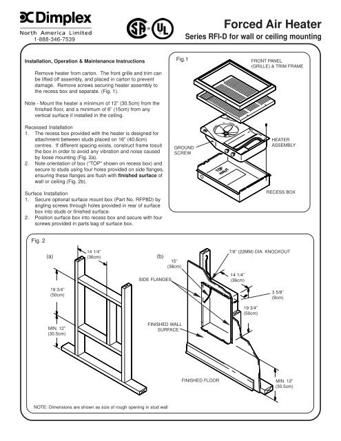
<strong>Installation</strong>, Operation & Maintenance Instructions<br />
Remove heater from carton. The front grille and trim can<br />
be lifted off assembly, and placed in carton to prevent<br />
damage. Remove screws securing heater assembly to<br />
the recess box and separate. (Fig. 1).<br />
Note - Mount the heater a minimum of 12” (30.5cm) from the<br />
finished floor, and a minimum of 6” (15cm) from any<br />
vertical surface if installed in the ceiling.<br />
Recessed <strong>Installation</strong><br />
1. The recess box provided with the heater is designed for<br />
attachment between studs placed on 16” (40.6cm)<br />
centres. If different spacing exists, construct frame tosuit<br />
the box in order to avoid any vibration and noise caused<br />
by loose mounting (Fig. 2a).<br />
2. Note orientation of box (“TOP” shown on recess box) and<br />
secure to studs using four holes provided on side flanges,<br />
ensuring these flanges are flush with finished surface of<br />
wall or ceiling (Fig. 2b).<br />
Surface <strong>Installation</strong><br />
1. Secure optional surface mount box (Part No. RFP8D) by<br />
angling screws through holes provided in rear of surface<br />
box into studs or finished surface.<br />
2. Position surface box into recess box and secure with four<br />
screws provided in parts bag of surface box.<br />
Fig.1<br />
GROUND<br />
SCREW<br />
FRONT PANEL<br />
(GRILLE) & TRIM FRAME<br />
HEATER<br />
ASSEMBLY<br />
RECESS BOX<br />
Fig. 2<br />
(a)<br />
14 1/4”<br />
(36cm)<br />
(b)<br />
15”<br />
(38cm)<br />
7/8” (22MM) DIA. KNOCKOUT<br />
SIDE FLANGES<br />
14 1/4”<br />
(36cm)<br />
19 3/4”<br />
(50cm)<br />
3 5/8”<br />
(9cm)<br />
19 3/4”<br />
(50cm)<br />
MIN. 12”<br />
(30.5cm)<br />
FINISHED WALL<br />
SURFACE<br />
FINISHED FLOOR<br />
MIN. 12”<br />
(30.5cm)<br />
NOTE: Dimensions are shown as size of rough opening in stud wall
Fig. 3<br />
A<br />
C<br />
(A)Place frame over top of tabs.<br />
(B) Push in at bottom until frame is flush with front panel.<br />
(C) Insert two screws to hold frame in place.<br />
C<br />
B<br />
Supply Wiring and Heater <strong>Installation</strong><br />
1. Insert approximately 15” (38cm) of supply wire into recess box through knockout provided in upper left hand corner (Fig. 2b).<br />
Wire should be rated for a minimum of 75°C (167°F)<br />
2. Connect power supply to terminals provided marked L1 and L2. Ground wire should be secured to green ground screw<br />
provided on side of heater assembly (Fig. 1).<br />
3. All units are factory prewired for operation with built-in thermostat. If remote thermostat operation is required follow<br />
appropriate wiring diagram located on inside of recess box.<br />
TIP - It is recommended that for ceiling mount applications a remote thermostat be used in order to provide superior temperature<br />
control.<br />
NOTE -All wiring must comply with National Electrical Code and local codes.<br />
4. Secure heater assembly to recess box using four 8 - 18 x 5/16” screws provided. Ensure that the four speed clips are<br />
attached to heater assembly top and bottom.<br />
Front Panel <strong>Installation</strong><br />
1. Remove trim frame from front panel assembly. (Fig. 3)<br />
2. If tamperproof built-in or remote thermostat operation is required, secure the louvered door to the front panel using 2 No. 6<br />
screws (not included) through the holes provided. The knob can then be removed and adjustment of the thermostat can be<br />
made using a slotted screwdriver through the front panel.<br />
3. Check to see that the fan blade is free to turn and that no residue remains in the unit. Front panel can then be secured to<br />
assembly using four 8 - 18 1/4” screws provided.<br />
Operation and Maintenance<br />
1. Set thermostat to desired temperature and both fan and heat should come on. Note that when desired temperature is<br />
reached the fan operation will continue for a short period after the elements have de-energized in order to remove residual<br />
heat from the unit.<br />
2. The fan motor is permanently lubricated and sealed at the factory and is maintenance free.<br />
3. It is suggested that at the beginning of each season the front panel is removed and the wire connection condition is checked<br />
and the unit is cleaned of dust and dirt with a vacuum cleaner.<br />
NOTE - Always open the circuit breaker to disconnect power to the unit prior to performing any maintenance or service operation.<br />
WARNING - Should the Over Temp light come on, disconnect power to the heater or turn down the thermostat fully<br />
counterclockwise and call a licenced electrician. DO NOT USE HEATER UNTIL PROBLEM IS<br />
DETERMINED AND FIXED.
WIRING DIAGRAM 1 WIRING DIAGRAM 2<br />
BUILT IN THERMOSTAT (FACTORY WIRED)<br />
S.P. “LINE” VOLTAGE REMOTE THERMOSTAT<br />
L2<br />
L2 (L-277V)<br />
L2<br />
L2 (L-277V)<br />
UNIT<br />
GND.<br />
THERMOSTAT<br />
L2<br />
CYCLE<br />
C<br />
L1<br />
L1<br />
OFF<br />
CAPACITOR<br />
B<br />
SUPPLY<br />
L1 (N-277V)<br />
A<br />
A<br />
D<br />
UNIT<br />
GND.<br />
THERMOSTAT<br />
L2<br />
CYCLE<br />
B<br />
C<br />
L1<br />
L1<br />
OFF<br />
A<br />
CAPACITOR<br />
SUPPLY<br />
L1 (N-277V)<br />
A<br />
B<br />
REMOTE<br />
SP STAT<br />
L<br />
L<br />
D<br />
THERMAL<br />
CUT OUT<br />
3<br />
2<br />
M<br />
THERMAL<br />
CUT OUT<br />
3<br />
2<br />
M<br />
1<br />
FAN DELAY<br />
1<br />
FAN DELAY<br />
NOTE: THIS WIRING REPRESENTS THE UNIT AS<br />
FACTORY WIRED. PLEASE CONSULT THE<br />
OTHER DIAGRAMS SHOWN AS TO WHAT<br />
OPTION IS REQUIRED. PLEASE ASSURE THAT<br />
ALL ELECTRICAL CLEARANCES ARE MET.<br />
WIRING DIAGRAM 3<br />
D.P. “LINE” VOLTAGE REMOTE THERMOSTAT<br />
1. MARR/TAPE WIRE LABELLED “L1” FROM THERMOSTAT<br />
2. DISCONNECT WIRE “B’ FROM MARR CONNECTOR “B”, MARR/TAPE WIRE<br />
“B” AS SHOWN OR REMOVE FROM THERMOSTAT CONNECTOR AND<br />
DISCARD<br />
3. CONNECT INCOMING SUPPLY “L1” TO CONNECTOR “A”<br />
4. CONNECT LOAD SIDE OF REMOTE LINE VOLTAGE THERMOSTAT TO MARR<br />
CONNECTOR “B” AS SHOWN<br />
5. CONNECT INCOMING POWER WIRE “L2” TO BOTH THE LINE SIDE OF<br />
REMOTE WALL THERMOSTAT AND WIRE ATTACHED TO BUILT IN<br />
THERMOSTAT WIRE LABELLED “L2” AS SHOWN.<br />
CUSTOMER WIRING<br />
CUSTOMER SUPPLIED<br />
THERMOSTAT<br />
L2<br />
L2<br />
L1<br />
L1<br />
L2 (L-277V)<br />
SUPPLY<br />
L1 (N-277V)<br />
CYCLE REMOTE D.P. STAT<br />
OFF<br />
L<br />
FACTORY SUPPLIED<br />
ON 240/208V UNITS ONLY<br />
CYCLE<br />
OFF<br />
UNIT<br />
GND.<br />
B<br />
C<br />
CAPACITOR<br />
A<br />
B<br />
L<br />
D<br />
THERMAL<br />
CUT OUT<br />
3<br />
2<br />
M<br />
1<br />
FAN DELAY<br />
1. MARR/TAPE WIRE LABELLED “L1” FROM THERMOSTAT<br />
2. DISCONNECT WIRE “B’ FROM MARR CONNECTOR “B”, MARR/TAPE<br />
WIRE “B” AS SHOWN OR REMOVE FROM THERMOSTAT CONNECTOR<br />
AND DISCARD.<br />
3. CONNECT LOAD SIDE OF REMOTE WALL THERMOSTAT TO MARR<br />
CONNECTORS “A” AND “B” AS SHOWN IN DIAGRAM.<br />
4. CONNECT INCOMING POWER WIRE “L2” TO BOTH THE LINE SIDE OF<br />
REMOTE WALL THERMOSTAT AND THE WIRE ATTACHED TO BUILT IN<br />
THERMOTAT WIRE LABELLED “L2”<br />
5. CONNECT THE OTHER INCOMING SUPPLY LINE TO THE LINE SIDE OF<br />
REMOTE WALL THERMOSTAT.
REPLACEMENT PARTS<br />
CATALOGUE NO. MOTOR CAPACITOR FAN BLADE ELEMENT CUT-OUT FAN DELAY THERMOSTAT FRONT PANEL KIT<br />
<strong>RFI</strong>815D31 00013004RP<br />
<strong>RFI</strong>FPA<br />
<strong>RFI</strong>815D31W 2000260600RP 3200070100RP<br />
00033001RP<br />
RPIFPW<br />
<strong>RFI</strong>820D31 00013002RP<br />
<strong>RFI</strong>FPA<br />
<strong>RFI</strong>820D31W RPIFPW<br />
<strong>RFI</strong>820D41 2000260200RP 3200070400RP<br />
00013008RP<br />
00033002RP<br />
<strong>RFI</strong>FPA<br />
<strong>RFI</strong>820D41W RPIFPW<br />
<strong>RFI</strong>830D31 2000260600RP 3200070100RP<br />
00013004RP<br />
00033001RP<br />
<strong>RFI</strong>FPA<br />
<strong>RFI</strong>830D31W RPIFPW<br />
<strong>RFI</strong>830D41 2000260200RP 3200070400RP 00010034RP 00013007RP 00009112RP 00033002RP 13678001RP<br />
<strong>RFI</strong>FPA<br />
<strong>RFI</strong>830D41W RPIFPW<br />
<strong>RFI</strong>840D21 00013001RP<br />
<strong>RFI</strong>FPA<br />
<strong>RFI</strong>840D21W 2000260600RP 3200070100RP<br />
00033001RP<br />
RPIFPW<br />
<strong>RFI</strong>840D31 00013002RP<br />
<strong>RFI</strong>FPA<br />
<strong>RFI</strong>840D31W RPIFPW<br />
<strong>RFI</strong>840D41 2000260200RP 3200070400RP<br />
00013008RP<br />
00033002RP<br />
<strong>RFI</strong>FPA<br />
<strong>RFI</strong>840D41W RPIFPW<br />
<strong>RFI</strong>848D31 2000260600RP 3200070100RP<br />
00013005RP<br />
00033001RP<br />
<strong>RFI</strong>FPA<br />
<strong>RFI</strong>848D31W RPIFPW<br />
7200610100 REV10