

Electronics & Communication 2004 lectronics ... - GATE Academy
Electronics & Communication 2004 lectronics ... - GATE Academy
Electronics & Communication 2004 lectronics ... - GATE Academy

You also want an ePaper? Increase the reach of your titles
YUMPU automatically turns print PDFs into web optimized ePapers that Google loves.
EC – <strong>2004</strong> www.gateacademy.co.in<br />
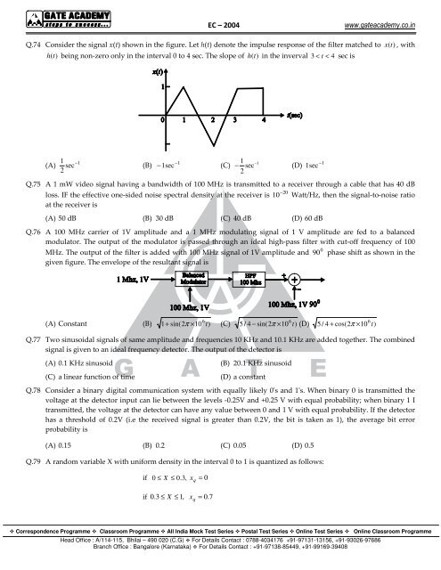
Q.74 Consider the signal x(t) shown in the figure. Let h(t) denote the impulse response of the filter matched to x (t)<br />
, with<br />
h (t) being non-zero only in the interval 0 to 4 sec. The slope of h (t)<br />
in the inverval 3 < t < 4 sec is<br />
(A)<br />
1 −1<br />
sec<br />
2<br />
(B)<br />
−1<br />
− 1sec<br />
(C)<br />
1 sec<br />
2<br />
−1<br />
− (D)<br />
Q.75 A 1 mW video signal having a bandwidth of 100 MHz is transmitted to a receiver through a cable that has 40 dB<br />
20<br />
loss. IF the effective one-sided noise spectral density at the receiver is 10 − Watt/Hz, then the signal-to-noise ratio<br />
at the receiver is<br />
(A) 50 dB (B) 30 dB (C) 40 dB (D) 60 dB<br />
Q.76 A 100 MHz carrier of 1V amplitude and a 1 MHz modulating signal of 1 V amplitude are fed to a balanced<br />
modulator. The output of the modulator is passed through an ideal high-pass filter with cut-off frequency of 100<br />
0<br />
MHz. The output of the filter is added with 100 MHz signal of 1V amplitude and 90 phase shift as shown in the<br />
given figure. The envelope of the resultant signal is<br />
1sec<br />
−1<br />
6 t<br />
(A) Constant (B) 1+ sin(2π × 10 ) (C) 5 / 4 − sin(2π × 10 ) (D) 5 / 4 + cos(2π<br />
× 10 )<br />
Q.77 Two sinusoidal signals of same amplitude and frequencies 10 KHz and 10.1 KHz are added together. The combined<br />
signal is given to an ideal frequency detector. The output of the detector is<br />
(A) 0.1 KHz sinusoid<br />
(C) a linear function of time<br />
(B) 20.1 KHz sinusoid<br />
(D) a constant<br />
Q.78 Consider a binary digital communication system with equally likely 0's and 1's. When binary 0 is transmitted the<br />
voltage at the detector input can lie between the levels -0.25V and +0.25 V with equal probability; when binary 1 I<br />
transmitted, the voltage at the detector can have any value between 0 and 1 V with equal probability. If the detector<br />
has a threshold of 0.2V (i.e the received signal is greater than 0.2V, the bit is taken as 1), the average bit error<br />
probability is<br />
(A) 0.15 (B) 0.2 (C) 0.05 (D) 0.5<br />
Q.79 A random variable X with uniform density in the interval 0 to 1 is quantized as follows:<br />
if 0 ≤ X ≤ 0.3,<br />
x = 0<br />
if 0 .3 ≤ X ≤ 1, x = 0. 7<br />
q<br />
q<br />
6 t<br />
6 t<br />
Correspondence Programme Classroom Programme All India Mock Test Series Postal Test Series Online Test Series Online Classroom Programme<br />
Head Office : A/114-115, Bhilai – 490 020 (C.G) For Details Contact : 0788-4034176 +91-97131-13156, +91-93026-97686<br />
Branch Office : Bangalore (Karnataka) For Details Contact : +91-97138-85449, +91-99169-39408