

Electronics & Communication 2004 lectronics ... - GATE Academy
Electronics & Communication 2004 lectronics ... - GATE Academy
Electronics & Communication 2004 lectronics ... - GATE Academy

You also want an ePaper? Increase the reach of your titles
YUMPU automatically turns print PDFs into web optimized ePapers that Google loves.
EC – <strong>2004</strong> www.gateacademy.co.in<br />
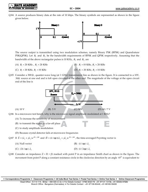
Q.84 A source produces binary data at the rate of 10 kbps. The binary symbols are represented as shown in the figure<br />
given below.<br />
The source output is transmitted using two modulation schemes, namely Binary PSK (BPSK) and Quandrature<br />
PSK(QPSK). Let B 1 and B 2 be the bandwidth requirements of BPSK and QPSK respectively. Assuming that the<br />
bandwidth of the above rectangular pulses is 10 KHz, B 1 and B 2 are<br />
(A) B<br />
1<br />
= 20 KHz , B<br />
2<br />
= 20 KHz<br />
(B) B1 = 10 KHz, B2<br />
= 20 KHz<br />
(C) B1 = 20 KHz, B2<br />
= 10 KHz<br />
(D) B1 = 20 KHz, B2<br />
= 10 KHz<br />
Q.85 Consider a 300 Ω , quanter-wave long (at 1 GHz) transmission line as shown in the figure. It is connected to a 10V,<br />
50 Ω source at one end and is left open circuited at the other end. The magnitude of the voltage at the open circuit<br />
end of the line is<br />
(A) 10 V (B) 5 V (C) 60V (D) 60 / 7 V<br />
Q.86 In a microwave test bench, why is the microwave signal amplitude modulated at 1 KHz<br />
(A) To increase the sensitivity of measurement<br />
(B) to transmit the signal to a far-off place<br />
(C) to study amplitude modulation<br />
(D) Because crystal detector fails at microwave frequencies<br />
<br />
<br />
jkz−<br />
jωt<br />
jkz−<br />
jωt<br />
Q.87 If E = ( aˆ<br />
+ jaˆ<br />
) e and H = ( k / ωµ )( aˆ<br />
+ jaˆ<br />
) e , the time-averaged Poynting vector is<br />
x<br />
y<br />
(A) Null vector (B) ( k / ωµ )<br />
(C) ( 2k<br />
/ ωµ ) â (D) ( k / 2ωµ<br />
)<br />
z<br />
y<br />
x<br />
Q.88 Consider an impedance Z = R + jX marked with point P in an impedance Smith chart as shown in the figure. The<br />
0<br />
movement from point P along a constant resistance circle in the clockwise direction by an angle 45 is equivalent to<br />
â z<br />
â z<br />
Correspondence Programme Classroom Programme All India Mock Test Series Postal Test Series Online Test Series Online Classroom Programme<br />
Head Office : A/114-115, Bhilai – 490 020 (C.G) For Details Contact : 0788-4034176 +91-97131-13156, +91-93026-97686<br />
Branch Office : Bangalore (Karnataka) For Details Contact : +91-97138-85449, +91-99169-39408