M20R 3810 Rev A page.. - Delta Aviation LLC
M20R 3810 Rev A page.. - Delta Aviation LLC
M20R 3810 Rev A page.. - Delta Aviation LLC

You also want an ePaper? Increase the reach of your titles
YUMPU automatically turns print PDFs into web optimized ePapers that Google loves.
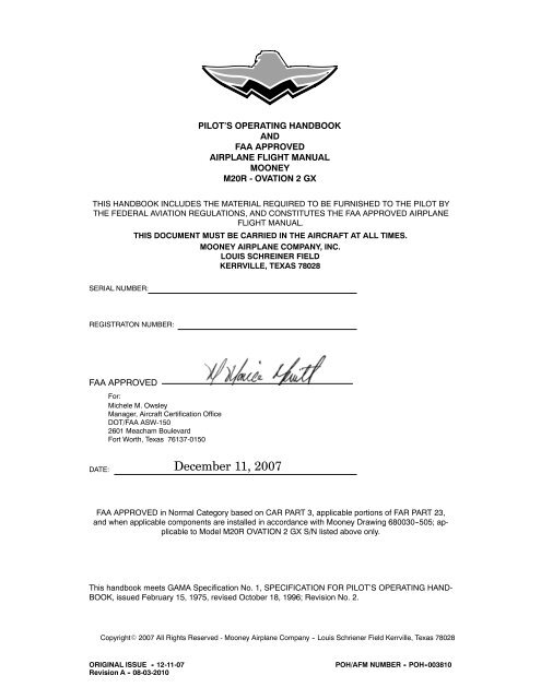
PILOT’S OPERATING HANDBOOK<br />
AND<br />
FAA APPROVED<br />
AIRPLANE FLIGHT MANUAL<br />
MOONEY<br />
<strong>M20R</strong> - OVATION 2 GX<br />
THIS HANDBOOK INCLUDES THE MATERIAL REQUIRED TO BE FURNISHED TO THE PILOT BY<br />
THE FEDERAL AVIATION REGULATIONS, AND CONSTITUTES THE FAA APPROVED AIRPLANE<br />
FLIGHT MANUAL.<br />
THIS DOCUMENT MUST BE CARRIED IN THE AIRCRAFT AT ALL TIMES.<br />
MOONEY AIRPLANE COMPANY, INC.<br />
LOUIS SCHREINER FIELD<br />
KERRVILLE, TEXAS 78028<br />
SERIAL NUMBER:<br />
REGISTRATON NUMBER:<br />
FAA APPROVED<br />
For:<br />
Michele M. Owsley<br />
Manager, Aircraft Certification Office<br />
DOT/FAA ASW-150<br />
2601 Meacham Boulevard<br />
Fort Worth, Texas 76137-0150<br />
DATE: December 11, 2007<br />
FAA APPROVED in Normal Category based on CAR PART 3, applicable portions of FAR PART 23,<br />
and when applicable components are installed in accordance with Mooney Drawing 680030--505; applicable<br />
to Model <strong>M20R</strong> OVATION 2 GX S/N listed above only.<br />
This handbook meets GAMA Specification No. 1, SPECIFICATION FOR PILOT’S OPERATING HAND-<br />
BOOK, issued February 15, 1975, revised October 18, 1996; <strong>Rev</strong>ision No. 2.<br />
CopyrightE 2007 All Rights Reserved - Mooney Airplane Company -- Louis Schriener Field Kerrville, Texas 78028<br />
ORIGINAL ISSUE - 12-11-07 POH/AFM NUMBER - POH -00<strong>3810</strong><br />
<strong>Rev</strong>ision A - 08-03-2010
BLANK<br />
MOONEY<br />
<strong>M20R</strong> - OVATION 2 GX
MOONEY<br />
<strong>M20R</strong> - OVATION 2 GX<br />
INTRODUCTION<br />
LIST OF EFFECTIVE PAGES<br />
ORIGINAL ISSUE ...................................................... 12-11-2007<br />
<strong>Rev</strong>ision A ............................................................. 08-03-2010<br />
Always destroy superseded <strong>page</strong>s when inserting revised <strong>page</strong>s.<br />
TITLE PAGE ..................................................... ORIGINAL ISSUE<br />
CONGRATULATIONS ............................................ ORIGINAL ISSUE<br />
i ...................................................................... 08-03-2010<br />
ii ..................................................................... 08-03-2010<br />
iii ..................................................................... 08-03-2010<br />
iv ..................................................................... 08-03-2010<br />
v ..................................................................... 08-03-2010<br />
vi ..................................................................... 08-03-2010<br />
vii .............................................................. ORIGINAL ISSUE<br />
viii .............................................................. ORIGINAL ISSUE<br />
1--1 ................................................................... 08-03-2010<br />
1--2 ............................................................. ORIGINAL ISSUE<br />
1--3 ............................................................. ORIGINAL ISSUE<br />
1--4 ............................................................. ORIGINAL ISSUE<br />
1--5 ................................................................... 08-03-2010<br />
1--6 ............................................................. ORIGINAL ISSUE<br />
1--7 ............................................................. ORIGINAL ISSUE<br />
1--8 ............................................................. ORIGINAL ISSUE<br />
1--9 ............................................................. ORIGINAL ISSUE<br />
1--10 ............................................................ ORIGINAL ISSUE<br />
1--11 ............................................................ ORIGINAL ISSUE<br />
1--12 ............................................................ ORIGINAL ISSUE<br />
1--13 .................................................................. 08-03-2010<br />
1--14 ............................................................ ORIGINAL ISSUE<br />
2--1 ................................................................... 08-03-2010<br />
2--2 ............................................................. ORIGINAL ISSUE<br />
2--3 ............................................................. ORIGINAL ISSUE<br />
2--4 ............................................................. ORIGINAL ISSUE<br />
2--5 ................................................................... 08-03-2010<br />
2--6 ................................................................... 08-03-2010<br />
2--7 ............................................................. ORIGINAL ISSUE<br />
2--8 ............................................................. ORIGINAL ISSUE<br />
2--9 ................................................................... 08-03-2010<br />
2--10 ............................................................ ORIGINAL ISSUE<br />
2--11 ............................................................ ORIGINAL ISSUE<br />
2--12 ............................................................ ORIGINAL ISSUE<br />
2--13 ............................................................ ORIGINAL ISSUE<br />
2--14 .................................................................. 08-03-2010<br />
2--15 .................................................................. 08-03-2010<br />
2--16 .................................................................. 08-03-2010<br />
2--17 .................................................................. 08-03-2010<br />
2--18 .................................................................. 08-03-2010<br />
2--19 .................................................................. 08-03-2010<br />
2--20 .................................................................. 08-03-2010<br />
3--1 ............................................................. ORIGINAL ISSUE<br />
3--2 ............................................................. ORIGINAL ISSUE<br />
3--3 ............................................................. ORIGINAL ISSUE<br />
3--4 ............................................................. ORIGINAL ISSUE<br />
3--5 ............................................................. ORIGINAL ISSUE<br />
3--6 ............................................................. ORIGINAL ISSUE<br />
3--7 ............................................................. ORIGINAL ISSUE<br />
ORIGINAL ISSUE - 12-11-07<br />
POH/AFM POH -00<strong>3810</strong><br />
<strong>Rev</strong>ision A -- 08-03-2010<br />
i<br />
This POH/AFM effective with S/N 29 -0495 THRU 29 -TBA
INTRODUCTION<br />
MOONEY<br />
M20TN<br />
3--8 ............................................................. ORIGINAL ISSUE<br />
3--9 ............................................................. ORIGINAL ISSUE<br />
3--10 ............................................................ ORIGINAL ISSUE<br />
3--11 ............................................................ ORIGINAL ISSUE<br />
3--12 ............................................................ ORIGINAL ISSUE<br />
3--13 ............................................................ ORIGINAL ISSUE<br />
3--14 ............................................................ ORIGINAL ISSUE<br />
3--15 ............................................................ ORIGINAL ISSUE<br />
3--16 ............................................................ ORIGINAL ISSUE<br />
3--17 ............................................................ ORIGINAL ISSUE<br />
3--18 ............................................................ ORIGINAL ISSUE<br />
3--19 ............................................................ ORIGINAL ISSUE<br />
3--20 ............................................................ ORIGINAL ISSUE<br />
3--21 ............................................................ ORIGINAL ISSUE<br />
3--22 ............................................................ ORIGINAL ISSUE<br />
4--1 ............................................................. ORIGINAL ISSUE<br />
4--2 ............................................................. ORIGINAL ISSUE<br />
4--3 ............................................................. ORIGINAL ISSUE<br />
4--4 ............................................................. ORIGINAL ISSUE<br />
4--5 ............................................................. ORIGINAL ISSUE<br />
4--6 ............................................................. ORIGINAL ISSUE<br />
4--7 ............................................................. ORIGINAL ISSUE<br />
4--8 ............................................................. ORIGINAL ISSUE<br />
4--9 ............................................................. ORIGINAL ISSUE<br />
4--10 ............................................................ ORIGINAL ISSUE<br />
4--11 ............................................................ ORIGINAL ISSUE<br />
4--12 ............................................................ ORIGINAL ISSUE<br />
4--13 ............................................................ ORIGINAL ISSUE<br />
4--14 ............................................................ ORIGINAL ISSUE<br />
4--15 ............................................................ ORIGINAL ISSUE<br />
4--16 ............................................................ ORIGINAL ISSUE<br />
5--1 ................................................................... 08-03-2010<br />
5--2 ............................................................. ORIGINAL ISSUE<br />
5--3 ............................................................. ORIGINAL ISSUE<br />
5--4 ................................................................... 08-03-2010<br />
5--5 ............................................................. ORIGINAL ISSUE<br />
5--6 ............................................................. ORIGINAL ISSUE<br />
5--7 ............................................................. ORIGINAL ISSUE<br />
5--8 ............................................................. ORIGINAL ISSUE<br />
5--9 ............................................................. ORIGINAL ISSUE<br />
5--10 ............................................................ ORIGINAL ISSUE<br />
5--11 ............................................................ ORIGINAL ISSUE<br />
5--12 ............................................................ ORIGINAL ISSUE<br />
5--13 ............................................................ ORIGINAL ISSUE<br />
5--14 ............................................................ ORIGINAL ISSUE<br />
5--15 ............................................................ ORIGINAL ISSUE<br />
5--16 ............................................................ ORIGINAL ISSUE<br />
5--17 ............................................................ ORIGINAL ISSUE<br />
5--18 ............................................................ ORIGINAL ISSUE<br />
5--19 ............................................................ ORIGINAL ISSUE<br />
5--20 ............................................................ ORIGINAL ISSUE<br />
5--21 ............................................................ ORIGINAL ISSUE<br />
5--22 ............................................................ ORIGINAL ISSUE<br />
5--23 ............................................................ ORIGINAL ISSUE<br />
5--24 ............................................................ ORIGINAL ISSUE<br />
5--25 ............................................................ ORIGINAL ISSUE<br />
POH/AFM POH -00<strong>3810</strong><br />
ORIGINAL ISSUE - 12-11-07<br />
ii<br />
<strong>Rev</strong>ision A -- 08-03-2010<br />
This POH/AFM effective with S/N 29 -0495 THRU 29 -TBA
MOONEY<br />
<strong>M20R</strong> - OVATION 2 GX<br />
INTRODUCTION<br />
5--26 ............................................................ ORIGINAL ISSUE<br />
5--27 ............................................................ ORIGINAL ISSUE<br />
5--28 ............................................................ ORIGINAL ISSUE<br />
5--29 ............................................................ ORIGINAL ISSUE<br />
5--30 ............................................................ ORIGINAL ISSUE<br />
5--31 ............................................................ ORIGINAL ISSUE<br />
5--32 ............................................................ ORIGINAL ISSUE<br />
5--33 ............................................................ ORIGINAL ISSUE<br />
5--34 ............................................................ ORIGINAL ISSUE<br />
6--1 ................................................................... 08-03-2010<br />
6--2 ............................................................. ORIGINAL ISSUE<br />
6--3 ............................................................. ORIGINAL ISSUE<br />
6--4 ............................................................. ORIGINAL ISSUE<br />
6--5 ............................................................. ORIGINAL ISSUE<br />
6--6 ............................................................. ORIGINAL ISSUE<br />
6--7 ............................................................. ORIGINAL ISSUE<br />
6--8 ................................................................... 08-03-2010<br />
6--9 ............................................................. ORIGINAL ISSUE<br />
6--10 ............................................................ ORIGINAL ISSUE<br />
6--11 ............................................................ ORIGINAL ISSUE<br />
6--12 ............................................................ ORIGINAL ISSUE<br />
6--13 ............................................................ ORIGINAL ISSUE<br />
6--14 .................................................................. 08-03-2010<br />
6--15 ............................................................ ORIGINAL ISSUE<br />
6--16 ............................................................ ORIGINAL ISSUE<br />
6--17 ............................................................ ORIGINAL ISSUE<br />
6--18 ............................................................ ORIGINAL ISSUE<br />
6--19 ............................................................ ORIGINAL ISSUE<br />
6--20 ............................................................ ORIGINAL ISSUE<br />
6--21 ............................................................ ORIGINAL ISSUE<br />
6--22 ............................................................ ORIGINAL ISSUE<br />
6--23 ............................................................ ORIGINAL ISSUE<br />
6--24 .................................................................. 08-03-2010<br />
6--25 .................................................................. 08-03-2010<br />
6--26 ............................................................ ORIGINAL ISSUE<br />
6--27 ............................................................ ORIGINAL ISSUE<br />
6--28 ............................................................ ORIGINAL ISSUE<br />
6--29 ............................................................ ORIGINAL ISSUE<br />
6--30 ............................................................ ORIGINAL ISSUE<br />
6--31 .................................................................. 08-03-2010<br />
6--32 ............................................................ ORIGINAL ISSUE<br />
7--1 ................................................................... 08-03-2010<br />
7--2 ................................................................... 08-03-2010<br />
7--3 ............................................................. ORIGINAL ISSUE<br />
7--4 ............................................................. ORIGINAL ISSUE<br />
7--5 ............................................................. ORIGINAL ISSUE<br />
7--6 ............................................................. ORIGINAL ISSUE<br />
7--7 ............................................................. ORIGINAL ISSUE<br />
7--8 ............................................................. ORIGINAL ISSUE<br />
7--9 ............................................................. ORIGINAL ISSUE<br />
7--10 ............................................................ ORIGINAL ISSUE<br />
7--11 ............................................................ ORIGINAL ISSUE<br />
7--12 ............................................................ ORIGINAL ISSUE<br />
7--13 ............................................................ ORIGINAL ISSUE<br />
7--14 ............................................................ ORIGINAL ISSUE<br />
7--15 ............................................................ ORIGINAL ISSUE<br />
ORIGINAL ISSUE - 12-11-07<br />
POH/AFM POH00<strong>3810</strong><br />
<strong>Rev</strong>ision A -- 08-03-2010<br />
iii<br />
This POH/AFM effective with S/N 29 -0495 THRU 29 -TBA
INTRODUCTION<br />
MOONEY<br />
M20TN<br />
7--16 ............................................................ ORIGINAL ISSUE<br />
7--17 ............................................................ ORIGINAL ISSUE<br />
7--18 ............................................................ ORIGINAL ISSUE<br />
7--19 ............................................................ ORIGINAL ISSUE<br />
7--20 ............................................................ ORIGINAL ISSUE<br />
7--21 .................................................................. 08-03-2010<br />
7--22 ............................................................ ORIGINAL ISSUE<br />
7--23 .................................................................. 08-03-2010<br />
7--24 ............................................................ ORIGINAL ISSUE<br />
7--25 ............................................................ ORIGINAL ISSUE<br />
7--26 ............................................................ ORIGINAL ISSUE<br />
7--27 ............................................................ ORIGINAL ISSUE<br />
7--28 ............................................................ ORIGINAL ISSUE<br />
7--29 ............................................................ ORIGINAL ISSUE<br />
7--30 ............................................................ ORIGINAL ISSUE<br />
7--31 ............................................................ ORIGINAL ISSUE<br />
7--32 ............................................................ ORIGINAL ISSUE<br />
7--33 ............................................................ ORIGINAL ISSUE<br />
7--34 ............................................................ ORIGINAL ISSUE<br />
7--35 ............................................................ ORIGINAL ISSUE<br />
7--36 ............................................................ ORIGINAL ISSUE<br />
7--37 ............................................................ ORIGINAL ISSUE<br />
7--38 ............................................................ ORIGINAL ISSUE<br />
8--1 ................................................................... 08-03-2010<br />
8--2 ............................................................. ORIGINAL ISSUE<br />
8--3 ............................................................. ORIGINAL ISSUE<br />
8--4 ............................................................. ORIGINAL ISSUE<br />
8--5 ............................................................. ORIGINAL ISSUE<br />
8--6 ............................................................. ORIGINAL ISSUE<br />
8--7 ................................................................... 08-03-2010<br />
8--8 ................................................................... 08-03-2010<br />
8--9 ............................................................. ORIGINAL ISSUE<br />
8--10 ............................................................ ORIGINAL ISSUE<br />
9--1 ............................................................. ORIGINAL ISSUE<br />
9--2 ............................................................. ORIGINAL ISSUE<br />
9--3 ............................................................. ORIGINAL ISSUE<br />
9--4 ............................................................. ORIGINAL ISSUE<br />
(Plus applicable supplements inserted)<br />
10--1 ............................................................ ORIGINAL ISSUE<br />
10--2 ............................................................ ORIGINAL ISSUE<br />
10--3 ............................................................ ORIGINAL ISSUE<br />
10--4 ............................................................ ORIGINAL ISSUE<br />
10--5 ............................................................ ORIGINAL ISSUE<br />
10--6 ............................................................ ORIGINAL ISSUE<br />
10--7 ............................................................ ORIGINAL ISSUE<br />
10--8 ............................................................ ORIGINAL ISSUE<br />
10--9 ............................................................ ORIGINAL ISSUE<br />
10--10 ........................................................... ORIGINAL ISSUE<br />
10--11 ........................................................... ORIGINAL ISSUE<br />
10--12 ........................................................... ORIGINAL ISSUE<br />
10--13 ........................................................... ORIGINAL ISSUE<br />
10--14 ........................................................... ORIGINAL ISSUE<br />
POH/AFM POH -00<strong>3810</strong><br />
iv<br />
This POH/AFM effective with S/N 29 -0495 THRU 29 -TBA<br />
ORIGINAL ISSUE - 12-11-07<br />
<strong>Rev</strong>ision A -- 08-03-2010
MOONEY<br />
<strong>M20R</strong> - OVATION 2 GX<br />
INTRODUCTION<br />
LOG OF REVISIONS<br />
This manual (POH<strong>3810</strong>) is a revision and re--issue of Pilot Operating Handbook (POH3800B),<br />
revised April 2005.<br />
REVISION<br />
NUMBER<br />
REVISED<br />
PAGES<br />
DESCRIPTION<br />
OF REVISIONS<br />
FAA<br />
APPROVED<br />
DATE<br />
ORIGINAL<br />
ISSUE<br />
ALL -<br />
12 -11 -2007<br />
A<br />
i thru viii<br />
1-1, 1-5, 1-13<br />
2-1, 2-5, 2-6,<br />
2-9<br />
2-14 thru 2-20<br />
5-1, 5-4<br />
6-1, 6-8, 6-14<br />
6-24, 6-25<br />
6-31<br />
7 -1, 7 -2, 7 -21,<br />
7-23<br />
8-1, 8-7, 8-8<br />
see<br />
Narrative<br />
Discussion<br />
of<br />
<strong>Rev</strong>isions<br />
Page vi<br />
08 -03 -2010<br />
ORIGINAL ISSUE - 12-11-07<br />
<strong>Rev</strong>ision A -- 08-03-2010<br />
POH/AFM POH -00<strong>3810</strong><br />
v
INTRODUCTION<br />
MOONEY<br />
<strong>M20R</strong> - OVATION 2 GX<br />
<strong>Rev</strong><br />
Level<br />
Page<br />
Number<br />
NARRATIVE DISCUSSION OF REVISIONS<br />
Comment<br />
A ithruiv <strong>Rev</strong>ised List of Effective Pages.<br />
A v&vi <strong>Rev</strong>ised Log of <strong>Rev</strong>isions and added Narrative Disussion of <strong>Rev</strong>isions.<br />
A 1-1 <strong>Rev</strong>ised Table of Contents<br />
A 1-5 Added Propeller Data -- TKS Booted Prop<br />
<strong>Rev</strong>ised Fuel Quantity to indicate Base Configuration<br />
A 1-13 Added Pressure Hectopascal scale<br />
A 2-1 <strong>Rev</strong>ised Table of Contents<br />
A 2-5 Added “Asterick” to note indicating G1000 display is bar versus<br />
standby instruments indicated with a band.<br />
Deleted extra “the” in Note, below Airspeed Markings.<br />
Added Propeller Data -- TKS Booted Prop<br />
A 2-6 Added EGT °Fto table, and added “White Arc= Recommended<br />
Climb to Green arc/bar column.<br />
A 2-9 Added the word “Heated” to Pitot System.<br />
A 2-14 <strong>Rev</strong>ised Instrument Light placard to indicate Bi-directional.<br />
A 2-15 <strong>Rev</strong>ised Operating Limitation placard (Areobatic to Aerobatic).<br />
Added Restraint Airbag placard.<br />
A 2-16 Added Fuel Selector placard (150085--037) 44.5 gal.<br />
Added Fuel Selector placard (150085--058) 50 gal.<br />
A 2-17 <strong>Rev</strong>ised “Fuel Flow” placard (150056--2032) to match engineering<br />
drawing.<br />
A 2-19 <strong>Rev</strong>ised “Fuel Filler Cap” placard (150056--2008) to match base<br />
configuration.<br />
A 2-20 Added placards (150056--2025, 150056--2007, 150056--4002) to<br />
match aircraft configuration.<br />
A 5-1 <strong>Rev</strong>ised Table of Contents.<br />
A 5-4 Added Propeller with de-ice boots.<br />
Added Removable Step to section.<br />
Added heading “Range Adjustment” to paragraph.<br />
Added Propeller with de-ice boots to performance heading.<br />
A 6-1 <strong>Rev</strong>ised Table of Contents.<br />
A 6-8 Added Extended Fuel Capacities to Problem Form.<br />
A 6-14 Added Propeller with TKS Boots to Equipment List.<br />
A 6-24 Added Synthetic Vision and Skywatch to Equipment List.<br />
A 6-25 Added 14 Volt Power Supply to Equipment List.<br />
A 6-31 Added 50 Gallon Fuel Capacity to Equipment List.<br />
A 7-1 <strong>Rev</strong>ised Table of Contents.<br />
A 7-21 Added “Optional” air filter that is cleanable to Air Induction System.<br />
A 7-23 Added Propeller with TKS Boots.<br />
A 8-1 <strong>Rev</strong>ised Table of Contents.<br />
A 8-7 & 8-8 Added Challenger Rechargable Air Filter to section.<br />
POH/AFM POH -00<strong>3810</strong> ORIGINAL ISSUE - 12-11-07<br />
vi<br />
<strong>Rev</strong>ision A -- 08-03-2010
MOONEY<br />
<strong>M20R</strong> - OVATION 2 GX<br />
SECTION I<br />
GENERAL<br />
TITLE<br />
TABLE OF CONTENTS<br />
................................................................. SECTION<br />
THREE VIEW (HARTZELL 3--BLADE PROPELLER) .............................. 1--3<br />
INTRODUCTION ............................................................. 1--4<br />
DESCRIPTIVE DATA ......................................................... 1--5<br />
ENGINE .................................................................. 1--5<br />
PROPELLER ............................................................. 1--5<br />
FUEL .................................................................... 1--5<br />
OIL ...................................................................... 1--6<br />
LANDING GEAR .......................................................... 1--6<br />
MAXIMUM CERTIFICATED WEIGHTS ....................................... 1--6<br />
STANDARD AIRPLANE WEIGHTS .......................................... 1--6<br />
CABIN & ENTRY DIMENSIONS ............................................. 1--6<br />
BAGGAGE SPACE & ENTRY DIMENSIONS .................................. 1--7<br />
SPECIFIC LOADINGS ..................................................... 1--7<br />
IDENTIFICATION PLATE ................................................... 1--7<br />
GARMIN G1000 ........................................................... 1--8<br />
SYMBOLS, ABBREVIATIONS & TERMINOLOGY ................................ 1--9<br />
GENERAL AIRSPEED TERMINOLOGY & SYMBOLS .......................... 1--9<br />
ENGINE POWER TERMINOLOGY .......................................... 1--9<br />
AIRPLANE PERFORMANCE & FLIGHT PLANNING TERMINOLOGY ........... 1--10<br />
ENGINE CONTROLS & INSTRUMENTS TERMINOLOGY ..................... 1--10<br />
METEOROLOGICAL TERMINOLOGY ...................................... 1--10<br />
WEIGHT & BALANCE TERMINOLOGY ..................................... 1--11<br />
MEASUREMENT CONVERSION TABLES ...................................... 1--12<br />
ORIGINAL ISSUE - 12-11-07<br />
<strong>Rev</strong>ision A -- 08-03-2010<br />
1--1
SECTION I<br />
GENERAL<br />
MOONEY<br />
<strong>M20R</strong> - OVATION 2 GX<br />
BLANK<br />
1--2 ORIGINAL ISSUE - 12-11-07
MOONEY<br />
<strong>M20R</strong> - OVATION 2 GX<br />
SECTION I<br />
GENERAL<br />
ENGINE<br />
DESCRIPTIVE DATA<br />
Number of Engines .............................................................. 1<br />
Engine Manufacturer .............................. Teledyne Continental Motors (TCM)<br />
Model ............................................................... IO--550--G(6)<br />
Recommended TBO .................................................... 2000 Hours<br />
Type .......................................... Reciprocating, air cooled, fuel injected<br />
Number of Cylinders ......................................... 6, Horizontally opposed<br />
Displacement ................................................. 550 Cu. In. (9014 cc)<br />
Bore ............................................................ 5.25 In. (13.3 cm)<br />
Stroke .......................................................... 4.25 In. (10.8 cm)<br />
Compression Ratio ......................................................... 8.5 : 1<br />
Fuel System<br />
Type ................................................................ Fuel Injection<br />
Make ....................................................................... TCM<br />
Fuel -- <strong>Aviation</strong> Gasoline ......................................... 100 octane --100LL<br />
Accessories<br />
Magnetos ...................................................... Bendix -- S6RN--25<br />
Ignition Harness ................................................... Shielded/Braided<br />
Spark Plugs ........................................ AC 273 (or equivalent) (18 m/m)<br />
Oil Cooler .......................................................... TCM Full Flow<br />
Alternator ................................................... 28 Volt DC, 100 AMPS<br />
Starter ................................................................. 24 volt DC<br />
Ratings:<br />
Maximum Take Off Sea Level BHP/RPM .................................... 280/2500<br />
PROPELLER<br />
Hartzell:<br />
Number ........................................................................ 1<br />
Manufacturer ............................................................. Hartzell<br />
Model Number ......................................... PHC--J3YF--1RF/F7693DF--2<br />
The (B) denotes a booted prop (for TKS) .............. PHC--J3YF--1RF/F7693DF(B)--2<br />
Number of Blades ............................................................... 3<br />
Diameter (MAX.) .................................................. 76 in. (193.0 cm)<br />
(MIN.) ........................................................... 75 in. (190.5 cm)<br />
Type .............................................................. Constant Speed<br />
Governor (McCauley) ............................. Hydraulically controlled by engine oil<br />
Blade Angles @ 30.0 in. Sta.:<br />
Low .................................................. 16.5 degrees +/-- 0.2 degrees<br />
High .................................................. 38.0 degrees +/-- 1.0 degrees<br />
FUEL<br />
Minimum Fuel Grade (Color) ...................... 100 LL (Blue) or 100 Octane (Green)<br />
Total Fuel Capacity -- Standard .............................. 95 U.S. Gal. (359.6 liters)<br />
Usable Fuel .............................................. 89 U.S. Gal. (336.9 liters)<br />
Unusable Fuel: ............................................... 6 U.S. Gal. (22.7 liters)<br />
ORIGINAL ISSUE - 12-11-07<br />
<strong>Rev</strong>ision A -- 08-03-2010<br />
1--5
SECTION I<br />
GENERAL<br />
MOONEY<br />
<strong>M20R</strong> - OVATION 2 GX<br />
OIL<br />
Oil Specification ........................................................ MHS-- 24( )<br />
and as Approved by TCM (Reference Engine Maintenance & Operators Manual)<br />
All Temperatures ................................................. 15W50 or 20W50<br />
Above 30 o F(--1 o C) Ambient Air (S.L.) ........................................ SAE 50<br />
Below 50 o F(10 o C) Ambient Air (S.L.) ................................. SAE 30, 10W30<br />
Total Oil Capacity ................................................. 8 Qts. (7.57 liters)<br />
Oil Filter ................................................................. Full Flow<br />
Oil grades, specifications and changing recommendations are contained in SECTION VIII.<br />
NOTE:<br />
The first time the airplane is filled with oil, additional oil is required for the filter, oil<br />
cooler and propeller dome. This oil is not drainable on subsequent oil changes. Added<br />
oil is mixed with a few quarts of older oil in the system.<br />
LANDING GEAR<br />
TYPE: Electrically operated, fully retractable tricycle gear with rubber shock discs. The main<br />
wheels have hydraulically operated disc brakes. The nose wheel is fully steerable 11 o left to 13 o<br />
right of center.<br />
Wheelbase ................................................. 79 9/16 in. (198.91 cm)<br />
Wheel Track ..................................................... 110 in. (279.4 cm)<br />
Tire Size:<br />
Nose .............................................................. 5.00 x 5 (6 ply)<br />
Main ............................................................... 6.00 x 6 (6 ply)<br />
Tire Pressure<br />
Nose .....................................................................<br />
Main ......................................................................<br />
49 PSI<br />
42 PSI<br />
Minimum Turning Radius (No brakes applied)<br />
Right ............................................................... 40 ft. (12.0 m)<br />
Left ................................................................. 48 ft. (14.4 m)<br />
MAXIMUM CERTIFICATED WEIGHTS<br />
Gross Weight .................................................. 3368 Lbs. (1528 Kg)<br />
Maximum Landing Weight ....................................... 3200 Lbs. (1452 Kg)<br />
Baggage Area ................................................... 120 Lbs. (54.4 Kg)<br />
Rear Storage Area ................................................. 10 Lbs. (4.5 Kg)<br />
Cargo (Rear Seats Folded Down) ................................ 340 Lbs. (154.2 Kg)<br />
STANDARD AIRPLANE WEIGHTS<br />
Basic Empty Weight ................................................ See Page 1--11<br />
Useful Load .......................................... Varies with installed equipment<br />
See SECTION VI for specific airplane weight.<br />
CABIN AND ENTRY DIMENSIONS<br />
Cabin Width (Maximum) .......................................... 43.5 In. (110.5 cm)<br />
Cabin Length (Maximum) ........................................... 126 In. (315 cm)<br />
Cabin Height (Maximum) ........................................... 44.5 In. (113 cm)<br />
Entry Width (Minimum) ............................................ 29.0 In. (73.4 cm)<br />
Entry Height (Minimum) ........................................... 35.0 In. (88.9 cm)<br />
1--6 ORIGINAL ISSUE - 12-11-07
MOONEY<br />
<strong>M20R</strong> - OVATION 2 GX<br />
SECTION I<br />
GENERAL<br />
WEIGHT<br />
U. S. Customary Unit .......................................... Metric Equivalents<br />
(Avoir du pois)<br />
1 grain ........................................................ 64.79891 milligrams<br />
1dram ............................................................... 1.772 grams<br />
1 ounce ............................................................. 28.350 grams<br />
1 pound .............................................................. 453.6 grams<br />
PRESSURE<br />
U.S. Customary Unit ........................................... Metric Equivalents<br />
1 PSIG ................................................................. 6.895 KPA<br />
1inchHg...............................................................<br />
3.388 KPA<br />
1 inch Hg ............................................................ 25.40 mm Hg<br />
COMMON CONVERSIONS<br />
1 pound/square foot .......................................... 0.488 kg/meter square<br />
1 pound/square inch .................................................. 2.036 inch Hg<br />
1 pound/HP .......................................................... 0.4538 kg/HP<br />
ATMOSPHERIC PRESSURE RELATIONSHIPS (IN. HG AND HECTOPASCAL)<br />
PRESSURE<br />
In. Hg hPa In. Hg hPa In. Hg hPa In. Hg hPa<br />
27.70 938 28.70 972 29.70 1006 30.65 1038<br />
27.75 940 28.75 974 9.75 1007 30.70 1040<br />
27.80 941 28.80 975 29.80 1009 30.75 1041<br />
27.85 943 28.85 977 29.85 1011 30.80 1043<br />
27.90 945 28.90 979 29.90 1013 30.85 1045<br />
27.95 946 28.95 980 29.92 1013 30.90 1046<br />
28.00 948 29.00 982 29.95 1014 30.95 1048<br />
28.05 950 29.05 984 30.00 1016 31.00 1050<br />
28.10 952 29.10 985 30.05 1018 31.05 1051<br />
28.15 953 29.15 987 30.10 1019 31.10 1053<br />
28.20 955 29.20 989 30.15 1021 31.15 1055<br />
28.25 957 29.25 991 30.20 1023 31.20 1057<br />
28.30 958 29.30 992 30.25 1024 31.25 1058<br />
28.35 960 29.35 994 30.30 1026 31.30 1060<br />
28.40 962 29.40 996 30.35 1028 31.35 1062<br />
28.45 963 29.45 997 30.40 1029 31.40 1063<br />
28.50 965 29.50 999 30.45 1031 31.45 1065<br />
28.55 967 29.55 1001 30.50 1033 31.50 1067<br />
28.60 969 29.60 1002 30.55 1035 31.55 1068<br />
28.65 970 29.65 1004 30.60 1036 31.60 1070<br />
ORIGINAL ISSUE - 12-11-07<br />
<strong>Rev</strong>ision A -- 08-03-2010<br />
1--13
SECTION I<br />
GENERAL<br />
MOONEY<br />
<strong>M20R</strong> - OVATION 2 GX<br />
USE OF THE TERMS WARNING, CAUTION AND NOTE<br />
The following conventions will be used for the terms Warning, Caution and Note:<br />
-WARNING -<br />
The use of a Warning symbol means that information which follows is of critical<br />
importance and concerns procedures and techniques which could cause or result<br />
in personal injury or death if not carefully followed.<br />
- CAUTION -<br />
The use of the Caution symbol means information which follows is of significant<br />
importance and concerns procedures and techniques which could cause or result<br />
in damage to the airplane and/or its equipment if not carefully followed.<br />
NOTE:<br />
The use of the term Note means the information that follows is essential to emphasize.<br />
1--14 ORIGINAL ISSUE - 12-11-07
MOONEY<br />
<strong>M20R</strong> - OVATION 2 GX<br />
SECTION II<br />
LIMITATIONS<br />
TITLE<br />
TABLE OF CONTENTS<br />
................................................................. SECTION<br />
INTRODUCTION ............................................................. 2--3<br />
NOISE LIMITS ............................................................... 2--3<br />
AIRSPEED LIMITATIONS ..................................................... 2--4<br />
AIRSPEED INDICATOR MARKINGS ............................................ 2--5<br />
POWER PLANT LIMITATIONS ................................................. 2--5<br />
POWER PLANT INSTRUMENT MARKINGS ..................................... 2--6<br />
FUEL LIMITATIONS .......................................................... 2--6<br />
WEIGHT LIMITATIONS ....................................................... 2--7<br />
CENTER OF GRAVITY (GEAR DOWN) ......................................... 2--7<br />
MANEUVER LIMITS .......................................................... 2--7<br />
FLIGHT LOAD FACTOR LIMITS ............................................... 2--7<br />
FLIGHT CREW .............................................................. 2--7<br />
OPERATING IMITATIONS ..................................................... 2--7<br />
KINDS OF OPERATION LIMITS ................................................ 2--8<br />
KINDS OF OPERATION EQUIPMENT LIST ..................................... 2--9<br />
TYPES OF OPERATION ..................................................... 2--10<br />
GENERAL .................................................................. 2--11<br />
G1000 SYSTEM .......................................................... 2--11<br />
ADVISORY MESSAGES ..................................................... 2--13<br />
DECALS & PLACARDS ...................................................... 2--14<br />
CABIN INTERIOR ........................................................ 2--14<br />
FUSELAGE INTERIOR .................................................... 2--18<br />
EXTERIOR .............................................................. 2--19<br />
FAA APPROVED<br />
ORIGINAL ISSUE - 12-11-07<br />
<strong>Rev</strong>ision A -- 08-03-2010<br />
AIRPLANE FLIGHT MANUAL<br />
2--1
SECTION II<br />
LIMITATIONS<br />
MOONEY<br />
<strong>M20R</strong> - OVATION 2 GX<br />
BLANK<br />
AIRPLANE FLIGHT MANUAL<br />
2--2<br />
FAA APPROVED<br />
ORIGINAL ISSUE - 12-11-07
MOONEY<br />
<strong>M20R</strong> - OVATION 2 GX<br />
SECTION II<br />
LIMITATIONS<br />
AIRSPEED MARKINGS<br />
Airspeed indicator markings, their color code and operational significance are shown in Figure<br />
2--2.<br />
MARKING IAS SIGNIFICANCE<br />
Red band*<br />
20 KIAS – 59 KIAS<br />
Low speed awareness --<br />
stall is imminent<br />
White band<br />
59 KIAS – 110 KIAS<br />
Operating range with flaps<br />
fully extended<br />
Green band 66 KIAS – 173 KIAS Normal operating range<br />
Yellow band<br />
174 KIAS -- 194 KIAS<br />
Caution range -- smooth air<br />
only<br />
Red band*<br />
194 KIAS and greater<br />
Lower limit of 195 KIAS is<br />
the maximum speed for all<br />
operations<br />
*The Indicated bar is for the G1000 display, while the standby instruments are<br />
marked with a band.<br />
Figure 2-2 AIRSPEED INDICATOR MARKINGS<br />
The airspeed indicator is marked in IAS values.<br />
POWER PLANT LIMITATIONS<br />
Number of Engines .............................................................. 1<br />
Engine Manufacturer .............................. Teledyne Continental Motors (TCM)<br />
Engine Model Number ............................................... IO--550--G(6) *<br />
Engine Operating Limits for Takeoff and Continuous Operations:<br />
Maximum Continuous Power ............................................... 280 BHP<br />
Maximum Continuous RPM .............................................. 2500 RPM<br />
Transient RPM Limit .................................................... 2600 RPM<br />
Maximum Cylinder Head Temperature ............................... 460 o F (237.7 o C)<br />
Maximum Oil Temperature ........................................... 240 o F(115 o C)<br />
Minimum Oil Temperature -- Takeoff ..................................... 75 o F(24 o C)<br />
Recommended Cruising Temperature ..................... 170 o F--200 o F(76 o C--93 o C)<br />
Oil Pressure:<br />
Normal Operating ....................................................... 30--60 PSI<br />
Minimum (IDLE ONLY) ...................................................... 10 PSI<br />
Oil Specification ........................ MHS--24( ), MHS--25( ) and TCM Approved oils<br />
Fuel Grade (Color) ........................... 100LL (Blue) ** or 100 octane (Green) **<br />
Number of Propellers ............................................................ 1<br />
Propeller Manufacturer ..................................................... Hartzell<br />
Propeller Hub/Blade Model Number ....................... PHC--J3YF--1RF/F7693DF--2<br />
The (B) denotes a booted prop (for TKS) .............. PHC--J3YF--1RF/F7693DF(B)--2<br />
Number of Blades ............................................................... 3<br />
Propeller Diameter:<br />
Min. ............................................................ 75 In. (190.5 cm.)<br />
Max. ............................................................ 76 In. (193.0 cm.)<br />
Propeller Blade Angles @ 30.0 In. sta.:<br />
Low ................................................. 16.5 Degrees +/-- 0.2 Degrees<br />
High ................................................. 38.0 Degrees +/-- 1.0 Degrees<br />
Propeller Operating Limits ............................................... 2500 RPM<br />
*Refer to MAC TCDS 2A3 for engine configuration required<br />
**100LL fuel is calibrated at 5.82 lb/gal (0.69 Kg/liter)<br />
100 octane fuel is calibrated at 6.0 lb. gal. (0.72 Kg/liter)<br />
FAA APPROVED<br />
ORIGINAL ISSUE - 12-11-07<br />
<strong>Rev</strong>ision A -- 08-03-2010<br />
AIRPLANE FLIGHT MANUAL<br />
2--5
SECTION II<br />
LIMITATIONS<br />
MOONEY<br />
<strong>M20R</strong> - OVATION 2 GX<br />
POWER PLANT INSTRUMENT MARKINGS<br />
Power plant instrument markings and their color code significance are shown in the table below.<br />
NOTE:<br />
When an indication lies in the caution range, the legend for that display will<br />
change to the color of the caution range. When an indication lies in the upper or<br />
lower prohibited range, the legend for that display will change to the color of the<br />
prohibited range and will begin flashing as well.<br />
INDICATION<br />
Red<br />
arc / bar<br />
=<br />
Lower<br />
prohibited<br />
range<br />
Yellow<br />
arc / bar<br />
=<br />
Caution<br />
range<br />
Green<br />
arc / bar<br />
=<br />
Normal<br />
operating<br />
range<br />
Yellow<br />
arc / bar<br />
=<br />
Caution<br />
range<br />
Red<br />
arc / bar<br />
=<br />
Upper<br />
prohibited<br />
range<br />
Engine RPM -- -- 2200 – 2500 -- 2500 – 2600*<br />
Manifold<br />
Press. In. Hg<br />
-- -- 10–35** -- --<br />
Oil Temp o F -- -- 75 o – 240 o -- >240 o<br />
Oil Press PSI 0–10 10–30 30 – 100 -- >100<br />
Cyl. Head<br />
Temp o F<br />
EGT o F -- --<br />
Fuel Flow<br />
gal/hr<br />
-- -- 250 – 460 -- >460<br />
1400 o -1450 o<br />
White Arc=<br />
Recommended Climb<br />
-- >1650 o<br />
-- -- 0--30*** -- --<br />
*To prevent nuisance alerts during normal takeoffs: the “RPM” and “MAP” data will not turn red or<br />
flash until the RPM exceeds 2540.<br />
** No color scale is depicted, and manifold pressure should be within this range.<br />
*** No color scale is depicted for fuel flow indication.<br />
FUEL LIMITATIONS<br />
-WARNING -<br />
Takeoff maneuvers when the selected fuel tank contains less than 12 gallons (45.4<br />
liters) of fuel have not been demonstrated.<br />
NOTE:<br />
Each fuel quantity gauge is calibrated to read zero only in coordinated level flight<br />
when remaining quantity of fuel can no longer be safely used.<br />
NOTE:<br />
An optional visual fuel quantity gauge is installed on top of each tank and is to be<br />
used as a reference for refueling tanks only.<br />
Standard Tanks (2) .................................. 47.5 U.S. Gal. each (179.8 liters)<br />
Total Fuel Capacity -- Standard .............................. 95 U.S. Gal. (359.6 liters)<br />
Usable Fuel .............................................. 89 U.S. Gal. (336.9 liters)<br />
Unusable Fuel: ............................................... 6 U.S. Gal. (22.7 liters)<br />
Fuel Grade (and color): ........ 100LL (low lead) (blue) or 100 octane (green) is approved<br />
- CAUTION -<br />
Ethylene glycol monomethyl ether (EGME) or other additives are not recommended<br />
due to potential deteriorating effects within the fuel system. Under certain conditions<br />
of temperature and humidity, water can be present in fuel in sufficient quantities to<br />
create ice formations within the fuel system. To prevent this, add Anhydrous ISOPRO-<br />
PYL Alcohol to the fuel supply in quantities not to exceed 3% of total fuel volume per<br />
tank.<br />
AIRPLANE FLIGHT MANUAL<br />
2--6<br />
FAA APPROVED<br />
ORIGINAL ISSUE - 12-11-07<br />
<strong>Rev</strong>ision A -- 08-03-2010
MOONEY<br />
<strong>M20R</strong> - OVATION 2 GX<br />
SECTION II<br />
LIMITATIONS<br />
KINDS OF OPERATION EQUIPMENT LIST<br />
SYSTEM or COMPONENT<br />
VFR<br />
DAY 1<br />
VFR<br />
NIGHT<br />
IFR<br />
DAY<br />
IFR<br />
NIGHT<br />
AIRSPEED INDICATOR 1 1 1 1<br />
ALTIMETER, SENSITIVE 1 1 1 1<br />
MAGNETIC DIRECTION INDICATOR 1 1 1 1<br />
MANIFOLD PRESSURE GAUGE -- -- -- --<br />
TACHOMETER 1 1 1 1<br />
FUEL QUANTITY INDICATOR 2 2 2 2<br />
OIL PRESSURE INDICATOR 1 1 1 1<br />
OIL TEMPERATURE INDICATOR 1 1 1 1<br />
CYLINDER HEAD TEMPERATURE INDI- 1 1 1 1<br />
CATOR<br />
AMMETER 1 1 1 1<br />
ALTERNATOR 1 1 1 1<br />
LANDING GEAR POSITION INDICATOR 2 2 2 2<br />
SEAT BELT & SHOULDER HARNESS 1 1 1 1<br />
FOR EACH OCCUPANT 2<br />
OXYGEN MASK FOR EACH OCCUPANT<br />
3<br />
1 1 1 1<br />
POSITION LIGHTS -- 3 -- 3<br />
STROBE LIGHTS (ANTI--COLLISION) -- 3 -- 3<br />
GYRO--HORIZON -- -- 1 1<br />
DIRECTIONAL GYRO -- -- 1 1<br />
TURN COORDINATOR or TURN & BANK -- -- 1 1<br />
INDICATOR<br />
LANDING LIGHT 4 -- 1 -- 1<br />
INSTRUMENT LIGHTS (INTERNAL or -- 1 -- 1<br />
GLARESHIELD)<br />
CLOCK (DIGITAL) -- -- 1 1<br />
COMMUNICATION SYSTEM -- -- 1 1<br />
NAVIGATION SYSTEM (APPROPRIATE -- -- 1 1<br />
TO FACILITIES BEING USED)<br />
BATTERIES 2 2 2 2<br />
FUEL BOOST PUMP 1 1 1 1<br />
PILOT’S OPERATING HANDBOOK & 1 1 1 1<br />
AIRPLANE FLIGHT MANUAL<br />
PITOT, HEATED 4 -- -- 1 1<br />
OAT GAUGE 4 -- -- 1 1<br />
VSI 4 -- -- 1 1<br />
ALTERNATE STATIC SOURCE 4 -- -- 1 1<br />
1 Equipment must be installed and operable for all operations<br />
2 If inoperative for unoccupied seat(s), seat(s) must be placarded, “DO NOT OCCUPY”<br />
3 Only required when the operating rules require use of oxygen<br />
4 When required by the appropriate regulations<br />
FAA APPROVED<br />
ORIGINAL ISSUE - 12-11-07<br />
<strong>Rev</strong>ision A -- 08-03-2010<br />
AIRPLANE FLIGHT MANUAL<br />
2--9
SECTION II<br />
LIMITATIONS<br />
MOONEY<br />
<strong>M20R</strong> - OVATION 2 GX<br />
TYPES OF OPERATION<br />
The airplane is approved for the following operations when equipped in accordance with FAR 91<br />
or FAR 135.<br />
1. Day V.F.R.<br />
2. Night V.F.R<br />
3. Day I.F.R.<br />
4. Night I.F.R.<br />
5. Non-Icing<br />
Minimum Operational Equipment for flight operations listed:<br />
EQUIPMENT<br />
NUMBER<br />
INSTALLED<br />
VFR DAY<br />
VFR<br />
NIGHT<br />
Primary Flight Display 1 * 1 1<br />
Multi--Function Display 1 -- 1 1<br />
Audio panel 1 -- -- 1<br />
Air data computer 1 1 1 1<br />
Attitude and Heading Reference<br />
System<br />
1 -- 1 1<br />
GPS 2 -- 1 2<br />
* If the PFD is inoperative or removed for service, the MFD may be used as the PFD. The MFD<br />
display must be operated in PFD (reversionary) mode by depressing the reversionary button on<br />
the Audio Panel. When operating in reversionary mode the system is limited to DAY VFR operations<br />
only.<br />
IFR<br />
AIRPLANE FLIGHT MANUAL<br />
2--10<br />
FAA APPROVED<br />
ORIGINAL ISSUE - 12-11-07
MOONEY<br />
<strong>M20R</strong> - OVATION 2 GX<br />
SECTION II<br />
LIMITATIONS<br />
ADVISORY MESSAGES<br />
The G1000 Cockpit Reference Guide and the G1000 Pilot’s Guide contain detailed descriptions<br />
of the annunciator system and all advisory messages. These messages appear on the PFD for<br />
flight crew awareness.<br />
The following warnings and cautions may appear in various locations on the PFD or MFD. Consult<br />
the G1000 Cockpit Reference Guide and the G1000 Pilot’s Guide for detailed descriptions of<br />
each annunciation as necessary.<br />
ANNUNCIATION<br />
AHRS Aligning – Keep Wings Level<br />
ATTITUDE FAIL<br />
AIRSPEED FAIL<br />
ALTITUDE FAIL<br />
VERT SPEED FAIL<br />
HDG<br />
Red X<br />
CAUSE<br />
Attitude and Heading Reference System is<br />
aligning. Keep wings level using standby<br />
attitude indicator.<br />
Display system is not receiving attitude reference<br />
information from the AHRS; accompanied<br />
by the removal of sky/ground presentation<br />
and a red X over the attitude area.<br />
Display system is not receiving airspeed input<br />
from the air data computer; accompanied<br />
by a red X through the airspeed display.<br />
Display system is not receiving airspeed input<br />
from the air data computer; accompanied<br />
by a red X through the altimeter display.<br />
Display system is not receiving vertical<br />
speed input from the air data computer; accompanied<br />
by a red X through the vertical<br />
speed display.<br />
Display system is not receiving valid heading<br />
input from the AHRS; accompanied by a<br />
red X through the digital heading display.<br />
A red X through any display field, such as<br />
COM frequencies, NAV frequencies, or engine<br />
data, indicates that display field is not<br />
receiving valid data.<br />
FAA APPROVED<br />
ORIGINAL ISSUE - 12-11-07<br />
AIRPLANE FLIGHT MANUAL<br />
2--13
SECTION II<br />
LIMITATIONS<br />
MOONEY<br />
<strong>M20R</strong> - OVATION 2 GX<br />
DECALS AND PLACARDS<br />
CABIN INTERIOR<br />
The following placards are relevant to proper operation of the airplane and must be installed inside<br />
the cabin at the locations specified.<br />
WHEN ORDERING DECALS & PLACARDS<br />
CONTACT MOONEY SERVICE PARTS DEPT.<br />
(X) = MATERIAL<br />
(Y) = COLOR OF INK<br />
SPEEDBRAKE EQUIPPED: FOR OPERATING INSTRUCTION<br />
AND LIMITATIONS SEE FAA APPROVED AFM SUPPLEMENT<br />
OR PILOT’S OPERATING HANDBOOK.<br />
150056--1001<br />
(OPTIONAL)<br />
ON INSTRUMENT<br />
PANEL<br />
NXXXX<br />
150056--(X)1004(Y)<br />
ON INSTRUMENT<br />
PANEL<br />
MIXTURE<br />
PUSH RICH<br />
PROP<br />
PUSH INCREASE<br />
THROTTLE<br />
PUSH INCREASE<br />
LIGHTNING DETECTION<br />
EQUIPMENT NOT TO BE<br />
USED FOR THUNDERSTORM<br />
AREA PENETRATION<br />
MIC<br />
150056--(X)3017(Y)<br />
(OPTIONAL)<br />
ON INSTRUMENT<br />
PANEL<br />
150056--(X)1012(Y)<br />
ON INSTRUMENT<br />
PANEL<br />
150056--(X)1010(Y)<br />
ON INSTRUMENT<br />
PANEL<br />
150056--(X)1007(Y)<br />
ON INSTRUMENT<br />
PANEL<br />
150056--(X)1008(Y)<br />
ON INSTRUMENT<br />
PANEL<br />
150056--303(CWS A/P DISC TRIM INTR)<br />
ON CONTROL<br />
YOKE<br />
GLARE<br />
SHIELD<br />
INSTRUMENT<br />
PANEL<br />
LIGHTS<br />
L<br />
A<br />
N<br />
D<br />
I<br />
N<br />
G<br />
G<br />
EAR<br />
PULL FOR<br />
ALTERNATE<br />
STATIC SOURCE<br />
GEAR NOT<br />
EXTENDED<br />
150056--(X)1056(Y)<br />
ON INSTRUMENT<br />
PANEL<br />
GEAR UP<br />
106 KIAS<br />
PUSH<br />
GEAR SAFETY<br />
BYPASS<br />
GEAR DOWN<br />
140 KIAS<br />
GEAR EXTD<br />
165 KIAS<br />
150056--(X)3038(Y)<br />
150085--038 (OPTIONAL)<br />
ON INSTRUMENT<br />
PANEL<br />
150056--1009<br />
ON INSTRUMENT<br />
PANEL<br />
AIRPLANE FLIGHT MANUAL<br />
2--14<br />
FAA APPROVED<br />
ORIGINAL ISSUE - 12-11-07<br />
<strong>Rev</strong>ision A -- 08-03-2010
MOONEY<br />
<strong>M20R</strong> - OVATION 2 GX<br />
SECTION II<br />
LIMITATIONS<br />
O PERAT ING<br />
L IM ITAT IO N S<br />
THE MARKINGS AND PLACARDS INSTALLED IN THIS AIRPLANE CONTAIN<br />
O P E RAT IN G L IM ITAT IO N S W H IC H M U S T B E C O M P L IE D W IT H W H E N<br />
OPERATING THIS AIRPLA NE IN THE NORMA L CATEGORY. THIS A IRPLA NE<br />
IS C ERT IFIED FO R DAY A N D N IG HT V FR/ IFR O PERAT IO N W H EN T H E<br />
REQUIRED EQUIPMENT IS INSTA LLED A ND OPERATIONA L. FLIGHT INTO<br />
K N O W N IC IN G C O N D IT IO N S IS P R O H IB IT E D . N O A ER<br />
OBATIC MA NEUVERS.<br />
INCLUDING SPINS A RE A PPROVED. OTHER OPERATING LIMITATIONS W HICH<br />
MUST BE COMPLIED W ITH W HEN OPERATING THIS A IRPLA NE IN THIS<br />
CATEGORY ARE CONTAINED IN THE AIRPLANE FLIGHT MANUAL.<br />
MA NEUVERING SPEED (33 6 8 LBS.), 127 KIAS, (26 0 0 LBS.) 111 KIAS.<br />
EMERGENCY MA NUA L GEA R EXTENSION<br />
1. PULL LA NDING GEA R ACT UATOR C IRC UIT BREA K ER.<br />
2 . PUT GEA R SW ITC H IN GEA R DOW N POSIT ION.<br />
3. PUSH RELEASE TA B FORWA RD AND LIFT UP RED HANDLE.<br />
4. PULL T--HANDLE STRAIGHT UP (12 TO 20 INCHES).<br />
5. ALLOW T--HANDLE TO RETURN TO ORIGINAL POSITION.<br />
6 . REPEAT UNTIL GEA R DOW N COMES ON (12 TO 20 PULLS). IF<br />
TOTA L ELECTRICA L FA ILURE--SEE MECHA NICA L INDICATOR.<br />
ON LEFT<br />
SIDE<br />
PANEL<br />
IN<br />
PILOT’S<br />
VISION<br />
CAUTION<br />
1. TURN OFF STROBE LITES W HEN TAXIING NEAR OTHER ACFT OR W HEN<br />
F LY IN G IN FO G O R IN C L O U D S . S T D P O S IT IO N L IT ES M U S T B E U S E D<br />
FOR ALL NIGHT OPERATIONS.<br />
2. IN CASE OF FIRE TURN OFF CA BIN HEAT .<br />
3. DO NOT SCREW VERNIER CONTROLS CLOSER THAN 1/ 8 ” FROM NUT<br />
FA C E .<br />
150056--(X)1032(Y)<br />
T<br />
A<br />
K<br />
E<br />
O<br />
F<br />
F<br />
CHECK LIST<br />
CONTROLS RUN--UP<br />
FUEL<br />
PROP<br />
INSTRUMENTS WING FLAPS<br />
TRIM<br />
SEAT LATCH<br />
BELT/HARNESS<br />
DOOR<br />
WINDOW<br />
ALT AIR<br />
PARK BRAKE<br />
MIXTURE<br />
CONDUCT RUDDER AND ELEVATOR TRIM CHECK PRIOR<br />
TO FLIGHT. SEE PILOT’S OPERATING HANDBOOK<br />
L<br />
D<br />
G<br />
BELT/HARNESS<br />
FUEL<br />
GEAR<br />
WING FLAPS<br />
MIXTURE<br />
PROP<br />
PARK BRAKE<br />
ON<br />
CONSOLE<br />
150056--(X)1030(Y)<br />
BELOW REAR SEAT<br />
150056--(X)3040(Y)<br />
(OPTIONAL)<br />
OXYGEN<br />
FLAP UP<br />
CONSOLE<br />
ABOVE &<br />
BELOW SWITCH<br />
PILOT’S L/H<br />
PANEL FWD<br />
OF ARM REST<br />
O<br />
F<br />
F<br />
O<br />
N<br />
FLAP DOWN<br />
130336--5<br />
(OPTIONAL)<br />
FAA APPROVED<br />
ORIGINAL ISSUE - 12-11-07<br />
<strong>Rev</strong>ision A -- 08-03-2010<br />
AIRPLANE FLIGHT MANUAL<br />
2--15
SECTION II<br />
LIMITATIONS<br />
MOONEY<br />
<strong>M20R</strong> - OVATION 2 GX<br />
WARNING:<br />
DO NOT EXCEED 170 LBS.<br />
(77.1 Kg) ON THIS SEAT BACK<br />
SEE AIRCRAFT LOADING SCHEDULE<br />
FWD END OF<br />
REAR SEAT BOTTOM<br />
STRUCTURE<br />
BAGGAGE DOOR<br />
FRAME<br />
LIGHT<br />
SWITCH<br />
150056--(X)1043(Y)<br />
FLOORBOARD<br />
BETWEEN<br />
SEATS<br />
150085--037<br />
AROUND EACH<br />
OXYGEN OUTLET<br />
ON OVERHEAD<br />
PANEL<br />
OXY--OH<br />
(OPTIONAL)<br />
FLOORBOARD<br />
BETWEEN<br />
SEATS<br />
150085--058<br />
(OPTIONAL)<br />
FLOORBOARD<br />
BETWEEN<br />
SEATS<br />
GEAR<br />
DOWN<br />
150056--(X)1015(Y)<br />
FUEL DRAIN<br />
PULL OPEN<br />
FLOORBOARD -- FWD OF<br />
CO--PILOT SEAT<br />
150056--(X)1036(Y)<br />
ABOVE<br />
INSIDE<br />
BAGGAGE<br />
DOOR<br />
HANDLE<br />
AUXILIARY EXIT<br />
DO NOT OPEN IN FLIGHT<br />
TO OPEN<br />
1. PULL OFF COVER<br />
2. PULL CABLE EXTRACTING LOCK PIN<br />
3. ACTUATE HANDLE<br />
TO CLOSE<br />
1. STORE HANDLE<br />
2. INSERT LOCK PIN<br />
3. INSTALL COVER<br />
4. CLOSE AND LATCH DOOR USING<br />
OUTSIDE HANDLE<br />
5. LOCK DOOR<br />
150056--(X)1045(Y)<br />
AIRPLANE FLIGHT MANUAL<br />
2--16<br />
FAA APPROVED<br />
ORIGINAL ISSUE - 12-11-07<br />
<strong>Rev</strong>ision A -- 08-03-2010
MOONEY<br />
<strong>M20R</strong> - OVATION 2 GX<br />
SECTION II<br />
LIMITATIONS<br />
UNDERSIDE OF<br />
FLOORBOARD<br />
ABOVE FUEL<br />
CHECK VALVE<br />
150056--(X)2032(Y)<br />
ON MAGNETIC<br />
COMPASS<br />
ALT AIR<br />
PULL ON<br />
917033--11<br />
DO NOT OPEN<br />
ABOVE 132 KIAS<br />
150056--(X)1031(Y)<br />
CONSOLE<br />
ON<br />
CONTROL<br />
KNOB<br />
BELOW<br />
PILOT’S<br />
STORM<br />
WINDOW<br />
150056--(X)1016(Y)<br />
CAUTION<br />
ABSENCE OF ELT LIGHT DURING FIRST<br />
3 SECONDS OF TEST INDICATE<br />
POSSIBLE G -SWITCH FAILURE<br />
ON RADIO PANEL<br />
ADJACENT TO ELT<br />
SWITCH<br />
WHEN APPLICABLE ELT<br />
UNIT IS INSTALLED<br />
150056--(X)1013(Y)<br />
LOWER FLT. PANEL<br />
NEXT TO THROTTLE<br />
(ALT LOCATION ON<br />
150056--(X)1019(Y) CONTROL YOKE)<br />
GO AROUND<br />
MUSIC<br />
IN<br />
150056--(X)3001(Y)<br />
ON<br />
INSTRUMENT<br />
PANEL<br />
BETWEEN SEATS ON<br />
EMERGENCY GEAR RELEASE<br />
EXTENSION HANDLE<br />
PUSH TO RELEASE<br />
150056--(X)1040(Y)<br />
WARNING<br />
DO NOT EXCEED 10 LBS (4.5Kg) IN THIS COMPARTMENT<br />
USE FOR STOWAGE OF LIGHT SOFT ARTICLES ONLY<br />
SEE AIRCRAFT LOADING SCHEDULE DATA<br />
FOR BAGGAGE COMPARTMENT ALLOWABLE<br />
150056--(X)1044(Y)<br />
BAGGAGE COMPARTMENT<br />
ON HAT RACK SHELF<br />
DO NOT EXCEED 120 LBS<br />
(54.4 Kg) IN THIS COMPARTMENT<br />
WARNING<br />
SEE AIRCRAFT LOADING SCHEDULE DATA<br />
FOR BAGGAGE COMPARTMENT ALLOWABLE<br />
TOP OF BAGGAGE<br />
DOOR JAMB<br />
150056--(X)1046(Y)<br />
FAA APPROVED<br />
ORIGINAL ISSUE - 12-11-07<br />
<strong>Rev</strong>ision A -- 08-03-2010<br />
AIRPLANE FLIGHT MANUAL<br />
2--17
SECTION II<br />
LIMITATIONS<br />
MOONEY<br />
<strong>M20R</strong> - OVATION 2 GX<br />
FUSELAGE INTERIOR<br />
The following placards are relevant to proper operation of the airplane and must be installed inside<br />
the fuselage at the locations specified.<br />
CAUTION<br />
THIS DOOR SHALL BE<br />
REMOVED AND STOWED<br />
WHEN FIELD TEMPERATURES<br />
O O<br />
EXCEED 30 F ( -1 C)<br />
ON KIT SLIDING DOOR<br />
AT OIL COOLER<br />
IF KIT INSTALLED<br />
150056--(X)2024(Y)<br />
ON OIL FILLER DOOR<br />
IF KIT INSTALLED<br />
CAUTION<br />
WINTERIZATION KIT INSTALLED<br />
WHEN OPERATING AT<br />
TEMPERATURES ABOVE 30OF ( -1OC)<br />
REMOVE OIL COOLER DOOR<br />
150056--(X)2002(Y)<br />
MAINTAIN<br />
LEVEL HERE<br />
150056--(X)2016(Y)<br />
HYDRAULIC OIL<br />
RESERVOIR<br />
BACKSIDE OF<br />
AUX. PWR.<br />
RECEPTACLE<br />
DOOR<br />
28 VOLTS<br />
ONLY<br />
150056--(X)2023(Y)<br />
USE AVIATORS<br />
OXYGEN ONLY<br />
SEE PILOT’S OPERATING<br />
HANDBOOK FOR<br />
FILLING PRESSURES<br />
150056--(X)2018(Y)<br />
INSIDE OXYGEN<br />
FILLER DOOR<br />
ON<br />
BATTERY<br />
ACCESS<br />
PANELS<br />
L/H & R/H<br />
BOTH<br />
BATTERIES<br />
MUST BE<br />
INSTALLED<br />
FOR FLIGHT<br />
150056--(X)2015(Y)<br />
- ENGINE OIL -<br />
OIL INSTALLED IN THIS ENGINE IS<br />
NEXT OIL CHANGE DUE AT<br />
(USE GREASE PENCIL)<br />
TACH TIME<br />
HRS<br />
INSIDE ENGINE<br />
OIL FILLER<br />
DOOR<br />
150056--(X)2001(Y)<br />
AIRPLANE FLIGHT MANUAL<br />
2--18<br />
FAA APPROVED<br />
ORIGINAL ISSUE - 12-11-07
MOONEY<br />
<strong>M20R</strong> - OVATION 2 GX<br />
SECTION II<br />
LIMITATIONS<br />
EXTERIOR<br />
The following placards are relevant to proper operation of the airplane and must be installed on<br />
the exterior of the aircraft at the locations specified.<br />
ON INBOARD END OF FLAP<br />
NO STEP WING LEADING EDGES AND<br />
WING AHEAD OF FLAPS<br />
150056--(X)2006(Y)<br />
UNDERSIDE OF WINGS (2 PLCS)<br />
& AFT OF L/H COWL FLAP (1 PLC)<br />
HOIST POINT<br />
150056--(X)2012(Y)<br />
DO NOT PUSH<br />
150056--(X)2019(Y)<br />
HORIZ. STAB. L/E<br />
RUDDER T/E (BOTH SIDES)<br />
UNDER TAILCONE<br />
AFT OF WING T/E<br />
STATIC DRAIN<br />
150056--(X)2014(Y)<br />
PITOT DRAIN<br />
150056--(X)2011(Y)<br />
UNDER LEFT WING L/E<br />
NEAR FUSELAGE<br />
UNDER WING NEAR<br />
SUMP DRAINS<br />
FUEL DRAIN<br />
150056--(X)2013(Y)<br />
GASCOLATOR<br />
DRAIN<br />
UNDER FUSELAGE RT. SIDE<br />
AFT OF NOSE WHEEL WELL<br />
150056--(X)2010(Y)<br />
2 ON MAIN LANDING<br />
TIRE PRESSURE 42 PSI (2.95 Kg/cm )<br />
GEAR DOOR<br />
150056--(X)2005(Y)<br />
2 ON NOSE LANDING<br />
TIRE PRESSURE 49 PSI (3.44 Kg/cm )<br />
GEAR DOOR<br />
150056--(X)2004(Y)<br />
TOWING LIMITS<br />
150056--(X)2022(Y)<br />
ON NOSE<br />
LANDING GEAR<br />
LEG ASSEMBLY<br />
ON BOTH FUEL<br />
FILLER CAPS<br />
WARNING<br />
DO NOT EXCEED<br />
TOWING LIMITS<br />
150056--(X)2003(Y)<br />
ON NOSE<br />
LANDING GEAR<br />
SPINDLE ASSEMBLY<br />
FUEL - 100 (GREEN) OR<br />
100LL (BLUE) MIN OCT<br />
44.5 U.S. GAL. USABLE<br />
168.5 LITERS USABLE<br />
150056--(X)2008(Y)<br />
FAA APPROVED<br />
ORIGINAL ISSUE - 12-11-07<br />
<strong>Rev</strong>ision A -- 08-03-2010<br />
AIRPLANE FLIGHT MANUAL<br />
2--19
SECTION II<br />
LIMITATIONS<br />
MOONEY<br />
<strong>M20R</strong> - OVATION 2 GX<br />
UNDER WING NEAR<br />
SUMP DRAINS<br />
150056--(X)2025(Y)<br />
TOP<br />
LEFT/RIGHT WINGS<br />
AT FUEL FILLERS<br />
150056--(X)2007(Y)<br />
TOP<br />
LEFT/RIGHT WINGS<br />
AT FUEL FILLERS<br />
150056--(X)4002(Y)<br />
(OPTIONAL)<br />
AIRPLANE FLIGHT MANUAL<br />
2--20<br />
FAA APPROVED<br />
ORIGINAL ISSUE - 12-11-07<br />
<strong>Rev</strong>ision A -- 08-03-2010
MOONEY<br />
<strong>M20R</strong> - OVATION 2 GX<br />
SECTION V<br />
PERFORMANCE<br />
TITLE<br />
TABLE OF CONTENTS<br />
................................................................. SECTION<br />
INTRODUCTION ............................................................. 5--3<br />
VARIABLES ................................................................. 5--3<br />
OPERATIONAL PROCEDURES FOR MAXIMUM FUEL EFFICIENCY ............... 5--3<br />
PERFORMANCE CONSIDERATIONS .......................................... 5--4<br />
- TABLES AND CHARTS -<br />
TEMPERATURE CONVERSION ............................................... 5--5<br />
CROSSWIND COMPONENT CHART ........................................... 5--6<br />
AIRSPEED CALIBRATION -- PRIMARY STATIC SYS (POWER ON, CLEAN) ......... 5--7<br />
AIRSPEED CALIBRATION -- PRIMARY STATIC SYS (POWER OFF, CLEAN) ........ 5--8<br />
AIRSPEED CALIBRATION -- PRIMARY STATIC SYS (POWER ON, 10° GR DWN) ... 5--9<br />
AIRSPEED CALIBRATION -- PRIMARY STATIC SYS (POWER OFF, 10° GR DWN) .. 5--10<br />
AIRSPEED CALIBRATION -- PRIMARY STATIC SYS (POWER ON, 33° GR DWN) .. 5--11<br />
AIRSPEED CALIBRATION -- PRIMARY STATIC SYS (POWER OFF, 33° GR DWN) .. 5--12<br />
AIRSPEED CALIBRATION -- ALTERNATE STATIC SYSTEM ...................... 5--13<br />
ALTIMETER CORRECTION -- PRIMARY STATIC SYSTEM ....................... 5--14<br />
ALTIMETER CORRECTION -- ALTERNATE STATIC SYSTEM .................... 5--15<br />
STALL SPEED VS ANGLE OF BANK .......................................... 5--16<br />
TAKEOFF DISTANCE -- HARD SURFACE (NORMAL) ........................... 5--18<br />
TAKEOFF DISTANCE -- HARD SURFACE (NORMAL) ........................... 5--19<br />
MAX RATE OF CLIMB (HARTZELL THREE BLADE PROP) ....................... 5--20<br />
RATE OF CLIMB -- CRUISE CLIMB ............................................ 5--21<br />
TIME--FUEL--DISTANCE TO CLIMB -- MAX CLIMB .............................. 5--22<br />
TIME--FUEL--DISTANCE TO CLIMB -- CRUISE CLIMB ........................... 5--23<br />
CRUISE POWER SETTINGS AND FUEL FLOWS<br />
BEST POWER ........................................................... 5--24<br />
BEST ECONOMY ........................................................ 5--25<br />
SPEED POWER VS ALTITUDE ............................................... 5--26<br />
RANGE<br />
BEST POWER ........................................................... 5--27<br />
BEST ECONOMY ........................................................ 5--28<br />
ENDURANCE<br />
BEST POWER ........................................................... 5--29<br />
BEST ECONOMY ........................................................ 5--30<br />
TIME--FUEL--DISTANCE TO DESCEND ........................................ 5--31<br />
LANDING DISTANCE -- NORMAL ............................................. 5--32<br />
LANDING DISTANCE -- NORMAL ............................................. 5--33<br />
ORIGINAL ISSUE - 12-11-2007<br />
<strong>Rev</strong>ision A -- 08-03-2010<br />
AIRPLANE FLIGHT MANUAL<br />
5--1
SECTION V<br />
PERFORMANCE<br />
MOONEY<br />
<strong>M20R</strong> - OVATION 2 GX<br />
BLANK<br />
AIRPLANE FLIGHT MANUAL ORIGINAL ISSUE - 12-11-2007<br />
5--2
MOONEY<br />
<strong>M20R</strong> - OVATION 2 GX<br />
SECTION V<br />
PERFORMANCE<br />
INTRODUCTION<br />
The purpose of this section is to present the owner or operator with information needed to facilitate<br />
planning of flights with reasonable accuracy.<br />
The Performance Data and charts presented herein are calculated, based on actual flight tests<br />
with the airplane and engine in good condition and the engine power control system properly<br />
adjusted.<br />
The flight test data has been corrected to International Standard Atmosphere conditions and<br />
then expanded analytically to cover various airplane gross weights, operating altitudes, and outside<br />
air temperatures.<br />
VARIABLES<br />
It is not possible to make allowances in the charts for varying levels of pilot technique, proficiency<br />
or environmental conditions. Mechanical or aerodynamic changes are not authorized because<br />
they can affect the performance or flight characteristics of the airplane. The effect of such things<br />
as soft runways, sloped runways, winds aloft or airplane configuration changes must be evaluated<br />
by the pilot. However, the performance on the charts can be duplicated by following the stated<br />
procedures in a properly maintained MOONEY <strong>M20R</strong> OVATION 2 GX.<br />
Examples are given to show how each chart is used. The only charts with no example are those<br />
where such an example of use would be repetitive.<br />
To obtain effect of altitude and OAT on aircraft performance:<br />
1. Set altimeter to 29.92 and read “pressure altitude”.<br />
2. Using the OAT grid for the applicable chart read the corresponding effect of OAT on performance.<br />
- CAUTION -<br />
Be sure to return to local altimeter setting in calculating aircraft elevation above sea<br />
level.<br />
OPERATIONAL PROCEDURES FOR MAXIMUM FUEL EFFICIENCY<br />
For maximum fuel efficiency on the <strong>M20R</strong> OVATION 2 GX, proper mixture leaning during cruise<br />
flight must be accomplished. The TCM IO--550--G(6) engine in the <strong>M20R</strong> OVATION 2 GX has<br />
been designed to attain maximum fuel efficiency at desired cruise power. Best power mixture (at<br />
2400 RPM) has been determined to be 50 o F(10 o C) rich of peak EGT. EGT is usually a more<br />
accurate indication of engine operation and fuel burn than indicated fuel flow. Therefore, it is recommended<br />
that the mixture be set using EGT as the primary reference instead of setting to a<br />
particular fuel flow.<br />
The following procedures is recommended for setting cruise power and leaning to best economy<br />
at 75% power or less.<br />
1. After leveling off, set manifold pressure and RPM for the desired cruise power settings as<br />
shown in this SECTION. At this point, mixture is at full rich from the climb.<br />
2. Slowly move mixture control toward lean while observing EGT indicator. If leaning mixture<br />
toward peak EGT causes the original manifold pressure setting to change, adjust throttle to<br />
maintain that desired cruise manifold pressure and continue leaning until best economy setting<br />
is obtained.<br />
ORIGINAL ISSUE - 12-11-2007<br />
AIRPLANE FLIGHT MANUAL<br />
5--3
SECTION V<br />
PERFORMANCE<br />
MOONEY<br />
<strong>M20R</strong> - OVATION 2 GX<br />
RANGE and ENDURANCE ASSUMPTIONS<br />
PERFORMANCE CONSIDERATIONS<br />
Range and endurance allowance is based on climbing at maximum continuous power to cruise<br />
altitude.<br />
Range and endurance reserves of 45 minutes at cruise power have been allowed for. Other conditions<br />
used for Range and Endurance are listed on each chart.<br />
OPTIONAL PROPELLER DE -ICE BOOTS (B) DESIGNATION<br />
With the optional propeller de--ice boots installed, expect climb performance to be degraded<br />
approximately 50 FPM from what is presented in the manual.<br />
REMOVABLE STEP<br />
The cruise speed tables herein were established with the aircraft step removed. Aircraft<br />
equipped with a removable step may have it removed or installed by a mechanic. If the step is<br />
installed decrease the true airspeed at normal cruise power setting by approximately 1 KTAS.<br />
LANDING GEAR DOORS<br />
When snow and ice are likely to be present on taxi and runway surfaces, inboard landing gear<br />
doors should be removed. Accumulation of ice and snow could prevent landing gear operation.<br />
If inboard landing gear doors are removed, a decrease in cruise speed and range can be expected<br />
and should be considered in preflight planning. To be conservative the following figures<br />
should be used:<br />
Decrease of true airspeed at normal cruise power setting by approximately 5 KTAS.<br />
RANGE ADJUSTMENT<br />
An approximate adjustment to range data shown in this manual can be made based on flight time<br />
planned with speed adjustment. For example, using the gear door cruise speed decrease for a 5<br />
hour flight will result in a decrease in range of approximately 25 N.M.:<br />
5 HR X 5 KTS = .......................................... 25 N.M. reduction in range.<br />
- CAUTION -<br />
Zero wind conditions seldom occur. In addition, varying atmospheric conditions, aircraft<br />
weight, mechanical condition of the aircraft and piloting techniques all affect the<br />
actual flight time and fuel used during a flight.<br />
It is the pilot’s responsibility to determine the actual operating conditions and plan<br />
the flight accordingly.<br />
Performance with the Hartzell three-blade PHC -J3YF -1RF/F7693DF -2 or<br />
PHC -J3YF -1RF/F7693DF(B) -2 propeller and A -2295 -10(P) Spinner installed is as follows:<br />
Takeoff Distance ............. Reference Takeoff Distance Chart -- Hard Surface (Normal)<br />
Climb Performance ........................... Reference Maximum Rate of Climb Chart<br />
AIRPLANE FLIGHT MANUAL ORIGINAL ISSUE - 12-11-2007<br />
5--4<br />
<strong>Rev</strong>ision A -- 08-03-2010
MOONEY<br />
<strong>M20R</strong> - OVATION 2 GX<br />
SECTION VI<br />
WEIGHT AND BALANCE<br />
TITLE<br />
TABLE OF CONTENTS<br />
................................................................. SECTION<br />
INTRODUCTION ............................................................. 6--3<br />
AIRPLANE WEIGHING PROCEDURE .......................................... 6--3<br />
WEIGHT & BALANCE CHART ................................................. 6--5<br />
OWNERS WEIGHT & BALANCE RECORD ...................................... 6--6<br />
PILOTS LOADING GUIDE ..................................................... 6--7<br />
PROBLEM FORM ............................................................ 6--8<br />
LOADING COMPUTATION GRAPH ............................................ 6--9<br />
CENTER OF GRAVITY MOMENT ENVELOPE .................................. 6--10<br />
CENTER OF GRAVITY LIMITS ENVELOPE .................................... 6--11<br />
FIXED BALLAST ............................................................ 6--12<br />
EQUIPMENT LIST .......................................................... 6--13<br />
NOTE:<br />
The empty weight, center of gravity and equipment list for the airplane as delivered<br />
from Mooney Airplane Company, Inc. is contained in this section. The use of this<br />
section is valid for use with the airplane identified below when approved by<br />
Mooney Airplane Company, Inc.<br />
MOONEY -- <strong>M20R</strong> OVATION 2 GX<br />
AIRCRAFT SERIAL NO.<br />
AIRCRAFT REGISTRATION NO.<br />
Mooney Airplane Company, Inc. - Approved Signature and Date<br />
ORIGINAL ISSUE - 12-11-07<br />
<strong>Rev</strong>ision A -- 08-03-2010<br />
AIRPLANE FLIGHT MANUAL<br />
6--1
SECTION VI<br />
WEIGHT AND BALANCE<br />
MOONEY<br />
<strong>M20R</strong> - OVATION 2 GX<br />
BLANK<br />
AIRPLANE FLIGHT MANUAL ORIGINAL ISSUE - 12-11-07<br />
6--2
MOONEY<br />
<strong>M20R</strong> - OVATION 2 GX<br />
SECTION VI<br />
WEIGHT AND BALANCE<br />
LOADING CALCULATION PROCEDURE<br />
PILOT’S LOADING GUIDE<br />
Proper loading of the aircraft is essential for maximum flight performance and safety. This<br />
section will assist you in determining whether the aircraft loading schedule is within the approved<br />
weight and center--of--gravity limits.<br />
To figure an actual loading problem for your aircraft, proceed as follows:<br />
Step 1. Refer to the latest entry on <strong>page</strong> 6--6 for the current empty weight and moment.<br />
NOTE:<br />
Since the engine oil is normally kept at the full level, the oil weight and moment is<br />
included in basic empty weight and is constant in calculating all loading problems.<br />
Step 2. Note the pilot’s weight and the position his seat will occupy in flight. Find this weight on<br />
the left scale of the Loading Computation Form (<strong>page</strong> 6--9) and cross the graph horizontally to<br />
the graph for #1 and #2 seats. When this point is located, drop down to the bottom scale to find<br />
the value of the moment/1000 due to the pilot’s weight and seat position.<br />
Repeat procedure for co--pilot and enter these weights and moment/1000 values in the proper<br />
sub--columns in the Problem Form on <strong>page</strong> 6--8/9.<br />
Step 3. Proceed as in Step 2 to account for the passengers in seats 3 and 4. Enter the weight and<br />
value of moment/1000 in the proper columns.<br />
Step 4. Again proceed as in Step 2 to account for the amount of fuel carried, and enter the weight<br />
and moment/1000 values in the proper columns.<br />
Step 5. Once more proceed as in Step 2 to account for the baggage to be carried and enter the<br />
figures in the proper columns.<br />
Step 6. Total the weight columns. This total must be 3368 Pounds (1528 Kg) or less. Total the<br />
Moment/1000 column.<br />
DO NOT FORGET TO SUBTRACT NEGATIVE NUMBERS.<br />
Step 7. Refer to the Center--of--Gravity Moment Envelope (<strong>page</strong> 6--10). Locate the loaded<br />
weight of your airplane on the left scale of the graph and trace a line horizontally to the right.<br />
Locate the total moment/1000 value for your airplane on the bottom scale of the graph and trace<br />
a line vertically above this point until the horizontal line for weight is intersected. If the point of<br />
intersection is within the shaded area, your aircraft loading is acceptable. If the point of intersection<br />
falls outside the shaded area, you must rearrange the load before take off.<br />
ORIGINAL ISSUE - 12-11-07<br />
AIRPLANE FLIGHT MANUAL<br />
6--7
SECTION VI<br />
WEIGHT AND BALANCE<br />
MOONEY<br />
<strong>M20R</strong> - OVATION 2 GX<br />
PROBLEM FORM<br />
STEP<br />
1<br />
2<br />
ITEM<br />
Pilot Seat (#1) *<br />
Co -Pilot Seat (#2) *<br />
WEIGHT<br />
(Kg)<br />
Lbs<br />
A/C Basic Empty Wt. (W.) (from<br />
<strong>page</strong> 6 -5) (includes Full Oil) (1009)<br />
8 Qts (7.57 Li) @ 1.875 Lbs/Qt<br />
(.80 Kg/Li) (Sta. -20.19) ( -51.3 cm)<br />
(Oil sump assumed FULL for 2225<br />
all flights)<br />
(77.1)<br />
(77.1)<br />
170<br />
170<br />
SAMPLE<br />
PROBLEM<br />
MOMENT<br />
(Kg -cm<br />
/1000)<br />
(114.6)<br />
99.46<br />
lb -in<br />
/1000<br />
(7.64)<br />
(aft pos)<br />
6.63<br />
(7.25)<br />
(2nd. pos)<br />
6.29<br />
WEIGHT<br />
(Kg)<br />
Lbs<br />
YOUR<br />
PROBLEM<br />
(Kg -cm<br />
/1000)<br />
MOMENT<br />
lb -in<br />
/1000<br />
Left Rear Seat (#3) or Cargo Area<br />
(77.1)<br />
170<br />
(14.3)<br />
12.41<br />
3<br />
Right Rear Seat (#4) or Cargo<br />
Area<br />
(77.1)<br />
170<br />
(14.3)<br />
12.41<br />
4<br />
Fuel<br />
(Max. Usable -<br />
100.0 Gal/582.0 Lbs.)<br />
(378.5 Li/264.0 Kg.) @ Sta 49.23<br />
(125 cm)<br />
Fuel<br />
(Max. Usable -<br />
102.0 Gal/593.6 Lbs.)<br />
(386.1 Li/266.4 Kg) @ Sta 49.23<br />
(125 cm)<br />
(164.7)<br />
363<br />
(164.7)<br />
363<br />
(20.59<br />
17.87<br />
(20.59)<br />
17.87<br />
Baggage (Max. 120 Lbs (54.4 Kg)<br />
@ Sta. 101.5 (257.8 cm)<br />
(45.4)<br />
100<br />
(11.70)<br />
10.15<br />
5<br />
Hat Rack (Max. 10 Lbs (4.54 Kg)<br />
@ Sta. 126.0 (320 CM)<br />
* Obtain the moment/1000 value for each seat position (FWD, MID or AFT)<br />
from loading computation graph.<br />
CONTINUE PROBLEM FORM ON NEXT PAGE<br />
AIRPLANE FLIGHT MANUAL ORIGINAL ISSUE - 12-11-07<br />
6--8<br />
<strong>Rev</strong>ision A 08-03-2010
MOONEY<br />
<strong>M20R</strong> - OVATION 2 GX<br />
SECTION VI<br />
WEIGHT AND BALANCE<br />
EQUIPMENT LIST MO.<br />
DAY<br />
MRS-EQ-A<br />
YEAR<br />
ITEM ITEM REF.<br />
WT.<br />
ARM<br />
MARK IF<br />
NO.<br />
DESCRIPTION<br />
DRAWING (Kg) (LBS) (cm) (INCHES) INSTALLED<br />
A. FIXED BALLAST<br />
1A<br />
2A<br />
3A<br />
WEIGHT ( -501 INSTL)<br />
WEIGHT ( -503 INSTL)<br />
WEIGHT ( -505 INSTL)<br />
350203<br />
350203<br />
350203<br />
(2.81)<br />
(6.08)<br />
(8.94)<br />
(532.1)<br />
6.2<br />
(532.1)<br />
13.4<br />
19.7<br />
(532.1)<br />
209.50<br />
209.50<br />
209.50<br />
ORIGINAL ISSUE - 12-11-07<br />
AIRPLANE FLIGHT MANUAL<br />
6--13
SECTION VI<br />
WEIGHT AND BALANCE<br />
MOONEY<br />
<strong>M20R</strong> - OVATION 2 GX<br />
EQUIPMENT LIST MO.<br />
DAY<br />
RS - EQ - B1<br />
YEAR<br />
ITEM ITEM REF.<br />
WT.<br />
ARM<br />
MARK IF<br />
NO.<br />
DESCRIPTION<br />
DRAWING (Kg) (LBS) (cm) (INCHES) INSTALLED<br />
B. POWERPLANT & ACCESSORIES<br />
1B<br />
ENGINE - TCM IO -550 -G(6) *, INCLUDES:<br />
STARTER, ALTERNATOR, EXHAUST,<br />
INDUCT. SYST., ALT. AIR, ENG. MT.,<br />
FULL OIL, PROP. GOV<br />
600270<br />
(249.3)<br />
549.5<br />
(159.16)<br />
-23.29<br />
X<br />
2B<br />
PROPELLER * - CONSTANT SPEED:<br />
HARTZELL - PHC -J3YF -1RF/F7693DF -2<br />
W/SPINNER<br />
680037<br />
(36.29)<br />
80.0<br />
( -125.7)<br />
-49.5<br />
3B<br />
PROPELLER * - CONSTANT SPEED:<br />
HARTZELL - PHC -J3YF -1RF/F7693DF(B) -2 (W/TKS Boots)<br />
W/SPINNER<br />
680037<br />
(36.29)<br />
80.0<br />
( -125.7)<br />
-49.5<br />
* Refer to Section I & II for engine/propeller configuration<br />
AIRPLANE FLIGHT MANUAL ORIGINAL ISSUE - 12-11-07<br />
6--14<br />
<strong>Rev</strong>ision A -- 08-03-2010
MOONEY<br />
<strong>M20R</strong> - OVATION 2 GX<br />
SECTION VI<br />
WEIGHT AND BALANCE<br />
EQUIPMENT LIST MO.<br />
DAY<br />
MRS-EQ-G1<br />
YEAR<br />
ITEM ITEM REF.<br />
WT.<br />
ARM<br />
MARK IF<br />
NO.<br />
DESCRIPTION<br />
DRAWING (Kg) (LBS) (cm) (INCHES) INSTALLED<br />
G. CABIN ACCOMODATIONS<br />
1G<br />
2G<br />
3G<br />
4G<br />
5G<br />
6G<br />
7G<br />
SUN VISORS (2)<br />
RESTRAINT ASSY, REAR (2)<br />
RESTRAINT ASSY, FWD (2)<br />
SEAT BELT ASSY, REAR (2)<br />
AMSAFE V23 SYSTEM (2)<br />
AMSAFE V23 SYSTEM (4)<br />
130250 (.32)<br />
140318<br />
140318<br />
140262<br />
140345<br />
140345<br />
(2.27)<br />
(2.27)<br />
(1.36)<br />
(3.91)<br />
(4.78)<br />
1.0<br />
5.0<br />
5.0<br />
3.0<br />
8.61<br />
10.53<br />
(83.8)<br />
(194.3)<br />
(106.7)<br />
(180.3)<br />
33.0<br />
76.48<br />
42.0<br />
71.0<br />
FW -(137.92) 54.3<br />
AFT -(145.03) 57.1<br />
FW -(137.92) 54.3<br />
AFT -(156.72) 61.7<br />
X<br />
8G<br />
9G<br />
10G<br />
11G<br />
12G<br />
ORIGINAL ISSUE - 12-11-07<br />
AIRPLANE FLIGHT MANUAL<br />
6--23
SECTION VI<br />
WEIGHT AND BALANCE<br />
MOONEY<br />
<strong>M20R</strong> - OVATION 2 GX<br />
EQUIPMENT LIST MO.<br />
DAY<br />
MRS-EQ-H1<br />
YEAR<br />
ITEM ITEM REF.<br />
WT.<br />
ARM<br />
MARK IF<br />
NO.<br />
DESCRIPTION<br />
DRAWING (Kg) (LBS) (cm) (INCHES) INSTALLED<br />
H. AVIONICS & AUTOPILOTS<br />
1H<br />
2H<br />
3H<br />
4H<br />
5H<br />
6H<br />
7H<br />
8H<br />
GARMIN G1000<br />
GARMIN GDL 69/69A<br />
GARMIN ADF<br />
KN 63 DME<br />
GARMIN GFC700 AUTOPILOT<br />
SYNTHETIC VISION SYSTEM<br />
SKYWATCH<br />
950300 (38.08)<br />
(208.28)<br />
83.95<br />
82.00<br />
950300 (1.28)<br />
(350.01)<br />
2.93<br />
137.80<br />
950300<br />
950300<br />
830153<br />
(3.44)<br />
(332.41)<br />
7.59<br />
130.87<br />
(1.36)<br />
(321.82)<br />
3.00<br />
126.70<br />
(7.60)<br />
16.75<br />
(286.56)<br />
112.82<br />
810515 -<br />
-<br />
-<br />
-<br />
810501 (5.50)<br />
(322.91)<br />
12.12<br />
127.13<br />
X<br />
X<br />
9H<br />
10H<br />
11H<br />
12H<br />
AIRPLANE FLIGHT MANUAL ORIGINAL ISSUE - 12-11-07<br />
6--24<br />
<strong>Rev</strong>ision A 08-03-2010
MOONEY<br />
<strong>M20R</strong> - OVATION 2 GX<br />
SECTION VI<br />
WEIGHT AND BALANCE<br />
EQUIPMENT LIST MO.<br />
DAY<br />
MRS-EQ-H2<br />
YEAR<br />
ITEM ITEM REF.<br />
WT.<br />
ARM<br />
MARK IF<br />
NO.<br />
DESCRIPTION<br />
DRAWING (Kg) (LBS) (cm) (INCHES) INSTALLED<br />
H. AVIONICS & AUTOPILOTS (CONT.)<br />
13H<br />
14H<br />
15H<br />
16H<br />
17H<br />
18H<br />
19H<br />
20H<br />
21H<br />
S -TEC AUTO PILOT SYSTEM 55X<br />
W/O AIR CONDITIONING<br />
W/ AIR CONDITIONING<br />
S -TEC ELECTRIC TRIM<br />
REIFF ENGINE HEATER<br />
14 VOLT POWER SUPPLY<br />
830084 (7.39)<br />
(179.17)<br />
16.29<br />
70.54<br />
830084<br />
950303<br />
800421<br />
(7.39)<br />
(186.03)<br />
16.29<br />
73.24<br />
(2.81)<br />
(334.47)<br />
6.20<br />
131.68<br />
(0.60)<br />
( -67.51)<br />
1.31<br />
-26.58<br />
NEGLIGIBLE ***<br />
***<br />
22H<br />
23H<br />
24H<br />
ORIGINAL ISSUE - 12-11-07<br />
<strong>Rev</strong>ision A -- 08-03-2010<br />
AIRPLANE FLIGHT MANUAL<br />
6--25
SECTION VI<br />
WEIGHT AND BALANCE<br />
MOONEY<br />
<strong>M20R</strong> - OVATION 2 GX<br />
EQUIPMENT LIST MO.<br />
DAY<br />
MRS-EQ-H3<br />
YEAR<br />
ITEM ITEM REF.<br />
WT.<br />
ARM<br />
MARK IF<br />
NO.<br />
DESCRIPTION<br />
DRAWING (Kg) (LBS) (cm) (INCHES) INSTALLED<br />
H. AVIONICS & AUTOPILOTS (CONT.)<br />
25H<br />
26H<br />
27H<br />
28H<br />
29H<br />
30H<br />
31H<br />
32H<br />
33H<br />
34H<br />
35H<br />
36H<br />
AIRPLANE FLIGHT MANUAL ORIGINAL ISSUE - 12-11-07<br />
6--26
MOONEY<br />
<strong>M20R</strong> - OVATION 2 GX<br />
SECTION VI<br />
WEIGHT AND BALANCE<br />
EQUIPMENT LIST MO.<br />
DAY<br />
MRS-EQ-J3<br />
YEAR<br />
ITEM ITEM REF.<br />
WT.<br />
ARM<br />
MARK IF<br />
NO.<br />
DESCRIPTION<br />
DRAWING (Kg) (LBS) (cm) (INCHES) INSTALLED<br />
J. OPTIONAL EQUIPMENT (CONT.)<br />
24J 51 GALLON CAPACITY USABLE FUEL TANKS (2)<br />
210217 -<br />
-<br />
(125.04)<br />
49.23<br />
25J 50 GALLON CAPACITY USABLE FUEL TANKS (2)<br />
210217 -<br />
-<br />
(125.04)<br />
49.23<br />
26J WX500 STORMSCOPE<br />
810447 (1.52)<br />
(374.45)<br />
3.34<br />
147.42<br />
27J<br />
28J<br />
29J<br />
30J<br />
31J<br />
OXYGEN SYSTEM (115.7 CU. FT.)<br />
OXYGEN SYSTEM (77.1 CU. FT.)<br />
AIR CONDITIONER (MINUS WTS.)<br />
870029<br />
870029<br />
(20.2)<br />
(347.9)<br />
44.55<br />
137.0<br />
(12.95)<br />
(347.98)<br />
28.56<br />
137.0<br />
770000 (30.0)<br />
(151.5)<br />
66.1<br />
59.7<br />
32J SPEEDBRAKE 2000<br />
950286<br />
(4.1)<br />
(180.3)<br />
9.0<br />
71.0<br />
33J<br />
34J<br />
35J<br />
ORIGINAL ISSUE - 12-11-07<br />
<strong>Rev</strong>ision A -- 08-03-2010<br />
AIRPLANE FLIGHT MANUAL<br />
6--31
SECTION VI<br />
WEIGHT AND BALANCE<br />
MOONEY<br />
<strong>M20R</strong> - OVATION 2 GX<br />
EQUIPMENT LIST MO.<br />
DAY<br />
MRS-EQ-J4<br />
YEAR<br />
ITEM ITEM REF.<br />
WT.<br />
ARM<br />
MARK IF<br />
NO.<br />
DESCRIPTION<br />
DRAWING (Kg) (LBS) (cm) (INCHES) INSTALLED<br />
J. OPTIONAL EQUIPMENT (CONT.)<br />
36J<br />
37J<br />
38J<br />
39J<br />
40J<br />
41J<br />
42J<br />
43J<br />
44J<br />
45J<br />
46J<br />
47J<br />
AIRPLANE FLIGHT MANUAL ORIGINAL ISSUE - 12-11-07<br />
6--32
MOONEY<br />
<strong>M20R</strong> - OVATION 2 GX<br />
SECTION VII<br />
AIRPLANE AND SYSTEM DESCRIPTION<br />
TITLE<br />
TABLE OF CONTENTS<br />
.................................................................<br />
SECTION<br />
INTRODUCTION ............................................................. 7--3<br />
AIRFRAME .................................................................. 7--3<br />
FLIGHT CONTROLS DESCRIPTION ........................................... 7--3<br />
AILERON SYSTEM ........................................................ 7--3<br />
RUDDER SYSTEM ........................................................ 7--4<br />
RUDDER TRIM SYSTEM ................................................... 7--4<br />
ELEVATOR SYSTEM ...................................................... 7--4<br />
ELEVATOR TRIM SYSTEM ................................................. 7--4<br />
WING FLAPS ............................................................. 7--4<br />
INSTRUMENT PANEL ........................................................ 7--4<br />
GARMIN G1000 ........................................................... 7--5<br />
FLIGHT PANEL & INSTRUMENTS ............................................. 7--8<br />
SWITCHES & CONTROLS ................................................. 7--8<br />
ANNUNCIATOR & SWITCH PANEL ........................................... 7--13<br />
GROUND CONTROL ........................................................ 7--14<br />
NOSE GEAR STEERING .................................................. 7--14<br />
TAXIING AND GROUND HANDLING ........................................ 7--14<br />
LANDING GEAR ............................................................ 7--15<br />
CONSTRUCTION ........................................................ 7--15<br />
RETRACTION SYSTEM ................................................... 7--15<br />
WHEEL BRAKES ......................................................... 7--15<br />
EMERGENCY EXTENSION SYSTEM ....................................... 7--15<br />
WARNING SYSTEM ...................................................... 7--15<br />
STEERING .............................................................. 7--16<br />
CABIN ..................................................................... 7--16<br />
BAGGAGE COMPARTMENT .............................................. 7--16<br />
CARGO RESTRAINT ..................................................... 7--16<br />
SEATS .................................................................. 7--17<br />
SEAT BELTS/SAFETY HARNESS .......................................... 7--17<br />
DOORS, WINDOWS & EXITS ................................................ 7--18<br />
CABIN DOOR ............................................................ 7--18<br />
PILOT’S WINDOW ........................................................ 7--18<br />
EMERGENCY EXITS ..................................................... 7--18<br />
ENGINE ................................................................... 7--18<br />
GENERAL ............................................................... 7--18<br />
ENGINE CONTROLS ..................................................... 7--18<br />
ENGINE INSTRUMENTS .................................................. 7--19<br />
ENGINE OPERATION AND CARE .......................................... 7--19<br />
OIL SYSTEM ............................................................ 7--19<br />
LUBRICATION SYSTEM .................................................. 7--20<br />
BREATHER FOR CRANKCASE ............................................ 7--20<br />
IGNITION SYSTEM ....................................................... 7--21<br />
AIR INDUCTION SYSTEM ................................................. 7--21<br />
ORIGINAL ISSUE - 12-11-07<br />
<strong>Rev</strong>ision A -- 08-03-2010<br />
AIRPLANE FLIGHT MANUAL<br />
7--1
SECTION VII<br />
AIRPLANE AND SYSTEM DESCRIPTION<br />
MOONEY<br />
<strong>M20R</strong> - OVATION 2 GX<br />
ICING PROTECTION ..................................................... 7--22<br />
EXHAUST SYSTEM ...................................................... 7--22<br />
FUEL INJECTION ........................................................ 7--22<br />
ENGINE COOLING AIR ................................................... 7--23<br />
ENGINE STARTING SYSTEM .............................................. 7--23<br />
ACCESSORIES ............................................................. 7--23<br />
EXHAUST GAS TEMPERATURE PROBE ................................... 7--23<br />
PROPELLER ............................................................... 7--23<br />
HARTZELL THREE BLADE ................................................ 7--23<br />
FUEL SYSTEM ............................................................. 7--25<br />
ELECTRICAL SYSTEM ...................................................... 7--26<br />
ALTERNATOR & (OPTIONAL) STAND-BY ALTERNATOR ..................... 7--26<br />
BATTERY ............................................................... 7--26<br />
ESSENTIAL BUS ......................................................... 7--26<br />
NON--ESSENTIAL BUS ................................................... 7--26<br />
EQUIPMENT LOCATION .................................................. 7--26<br />
SCHEMATIC ............................................................. 7--27<br />
CIRCUIT BREAKER PANEL ............................................... 7--28<br />
ACCESSORIES .......................................................... 7--29<br />
ANNUNCIATOR PANEL ................................................... 7--29<br />
ELT PANEL .............................................................. 7--30<br />
LIGHTING SYSTEM ......................................................... 7--30<br />
INSTRUMENT & PLACARD LIGHTS ........................................ 7--30<br />
MAP LIGHT .............................................................. 7--30<br />
CABIN LIGHTING ........................................................ 7--30<br />
EXTERIOR LIGHTING .................................................... 7--30<br />
CABIN ENVIRONMENT ...................................................... 7--31<br />
HEATING & VENTILATION SYSTEMS ...................................... 7--31<br />
PITOT PRESSURE & STATIC SYSTEM ........................................ 7--32<br />
STALL WARNING SYSTEM .................................................. 7--32<br />
OXYGEN SYSTEM .......................................................... 7--33<br />
VACUUM SYSTEM .......................................................... 7--36<br />
EMERGENCY LOCATOR TRANSMITTER ...................................... 7--37<br />
ELT REMOTE SWITCH OPERATION ....................................... 7--37<br />
AIRPLANE FLIGHT MANUAL ORIGINAL ISSUE - 12-11-07<br />
7--2<br />
<strong>Rev</strong>ision A -- 08-03-2010
MOONEY<br />
<strong>M20R</strong> - OVATION 2 GX<br />
SECTION VII<br />
AIRPLANE AND SYSTEM DESCRIPTION<br />
IGNITION SYSTEM<br />
Power from the engine crankshaft is transmitted through camshaft gear to the magneto drive<br />
gears, which in turn drives the magneto drive couplings. The left magneto incorporates an impulse<br />
coupling. As the rubber bushings in the drive gear turns the coupling drive lugs, counterweighted<br />
latch pawls inside the coupling cover, engage pins on the magneto case and hold back<br />
the latch plate until forced inward by the coupling cover. When the latch plate is released, the<br />
coupling spring spins the magneto shaft through its neutral position and the breaker opens to<br />
produce a high voltage surge in the secondary coil. The spring action permits the latch plate,<br />
magnet and breaker to be delayed through a lag angle of 30 degrees of drive gear rotation during<br />
the engine cranking period. Two lobes on the breaker cam produce two sparks per revolution of<br />
the drive shaft. After engine is running, counter--weights hold the latch pawls away from the stop<br />
pins and the magneto shaft is driven at full advance.<br />
The engine firing order is 1--6--3--2--5--4. Ignition harnesses are connected to the magnetos so<br />
right magneto fires the upper plugs on the right side and lower plugs on the left. The left magneto<br />
fires the upper plugs on the left and lower plugs on the right. The magneto cases, spark plugs,<br />
harnesses and connections are shielded to prevent radio interference.<br />
FILTER<br />
NACA AIR INLET<br />
FILTER CAN<br />
FUEL<br />
CONTROL<br />
UNIT<br />
ALT.<br />
AIR<br />
BOX<br />
ENGINE INDUCTION<br />
AIR SYSTEM<br />
FIGURE 7 -6 AIR INDUCTION SYSTEM SCHEMATIC<br />
AIR INDUCTION SYSTEM<br />
The engine air induction system consists of a NACA, flush--type air inlet duct located on front of<br />
lower cowling. The air inlet duct incorporates the air filter housing. This housing contains a<br />
throw--away, paper canister type air filter element. The optional air filter is cleanable and must be<br />
serviced at 100 hour intervals. Refer the maintenance manual for instructions.<br />
A secondary or alternate air source for combustion air is provided. This air inlet has a spring<br />
loaded door which normally remains closed. If the air filter or induction air inlet should become<br />
ORIGINAL ISSUE - 12-11-07<br />
<strong>Rev</strong>ision A -- 08-03-2010<br />
AIRPLANE FLIGHT MANUAL<br />
7--21
SECTION VII<br />
AIRPLANE AND SYSTEM DESCRIPTION<br />
MOONEY<br />
<strong>M20R</strong> - OVATION 2 GX<br />
restricted, the alternate air door will automatically open. Warmer air will then be drawn from the<br />
engine compartment. There will be a reduction of engine power when the alternate air door is<br />
open due to lower inlet air pressure and higher air temperature. Whenever the alternate air door<br />
is open, a switch will activate the “ALT AIR” annunciator light on the panel to alert the pilot.<br />
ICING PROTECTION<br />
Continued operation of the induction system in the event of intake air being obstructed is provided<br />
by activation of the alternate air system. The alternate air is automatically or manually controlled.<br />
When the door is opened, unfiltered, relatively warm air, from engine compartment, is<br />
admitted into the induction system.<br />
EXHAUST SYSTEM<br />
The exhaust system consists of tubes from each cylinder mating into a muffler under the engine<br />
crankcase. The right collector pipe crosses through muffler and out an exhaust pipe on the left<br />
side of aircraft. The left collector pipe crosses through muffler and out an exhaust pipe on the<br />
right side of aircraft. A short tailpipe attaches to the end of each exhaust pipe.<br />
The muffler has a heat shroud around it which serves as a cabin air heater. Outside ambient air is<br />
forced into the cabin heater by forward velocity. Air flows around the muffler, picking up heat and<br />
is then carried to a cabin heat J--box mounted on the firewall. When cabin heat is not required,<br />
the air continues to flow around the muffler for cooling and is dumped overboard through the<br />
cabin heat J--box outlet duct.<br />
FUEL INJECTION<br />
The fuel injection system is of the multi--nozzle, continuous flow type which controls fuel flow to<br />
match engine requirements. Any change in air throttle position, engine speed or a combination<br />
of these causes changes in fuel pressure in direct relation to engine requirements. A manual<br />
mixture control is provided for precise leaning at any altitude and power setting. A fuel flow system<br />
is installed for digital read out of fuel flow in gallons per hour. However, fuel flow is NOT to be<br />
used as reference for manual leaning. Use the EGT gauge for this purpose.<br />
The continuous--flow system permits the use of a typical rotary vane pump with integral relief<br />
valve. With this system there is no need for an intricate mechanism for timing fuel injection to the<br />
engine. The fuel injector pump is equipped with a separator where vapor is separated by a swirling<br />
augmenter system from the liquid fuel and returned to the tank selected. The fuel injector<br />
pump forces liquid fuel into the metering unit assembly.<br />
The fuel metering unit/air throttle controls the amount of intake air admitted into the intake manifold<br />
and meters the proportionate amount of fuel to the fuel manifold valve. The assembly has<br />
three control units, one for air, in the air throttle assembly, and two for the fuel control unit.<br />
The manifold valve receives fuel from the metering unit. When fuel pressure reaches approximately<br />
3.5 PSI, a check valve opens and admits fuel to six ports in the manifold valve (one port<br />
for each fuel nozzle line). The manifold valve also serves to provide a clean cut off of fuel to the<br />
cylinder when engine is shut down.<br />
The injector nozzle lines connect the manifold valve to the six fuel injector nozzles.<br />
The injector nozzles (one per cylinder) are “air bleed” type fuel nozzles which spray fuel directly<br />
into the intake port of the cylinder. When engine is running, flow through the nozzle is continuous<br />
and will enter the cylinder combustion chamber when the intake valve opens.<br />
Since the size of the fuel nozzles are fixed, the amount of fuel flowing through them is determined<br />
by the pressure applied. For this reason, fuel flow may be accurately determined by measuring<br />
fuel pressure at the manifold valve.<br />
AIRPLANE FLIGHT MANUAL ORIGINAL ISSUE - 12-11-07<br />
7--22
MOONEY<br />
<strong>M20R</strong> - OVATION 2 GX<br />
SECTION VII<br />
AIRPLANE AND SYSTEM DESCRIPTION<br />
ENGINE COOLING AIR<br />
Ram air is drawn into the forward part of upper cowl and flows down, around the cylinders using<br />
several baffles to control air direction. Hot air, off the cylinders, exits cowl thru lower cowl<br />
openings, located on either side of engine lower cowl, immediately forward of the firewall.<br />
ENGINE STARTING SYSTEM<br />
Engine starting is provided by a 24 volt starter. A starter engaged warning light (START POWER)<br />
is incorporated as standard equipment in annunciator panel. Ignition is provided by an impulse<br />
coupled magneto.<br />
The engine firing order is 1--6--3--2--5--4. The ignition harnesses are connected to the magnetos<br />
so the right magneto fires the upper plugs on the right side and lower plugs on the left. The left<br />
magneto fires the upper plugs on the left and the lower plugs on the right.<br />
EXHAUST GAS TEMPERATURE PROBE<br />
ACCESSORIES<br />
The exhaust gas temperature (EGT) probe measures exhaust gas temperature as it exits the<br />
exhaust valves into the exhaust manifold. The EGT probe varies electrical current (milliamps),<br />
based on exhaust gas temperature, and displays this data on the Garmin GDU 1040 Multi--Function<br />
Display. The EGT gauge is used as the primary source to lean fuel mixture.<br />
PROPELLER<br />
HARTZELL THREE BLADE<br />
PHC -J3YF -1RF/F7693DF -2 or PHC -J3YF -1RF/F7693DF(B) -2<br />
The (B) denotes a booted prop (for TKS)<br />
The propeller is a three--blade, 76 inch (193 cm.) diameter, constant speed unit that features<br />
aluminum blades in an aluminum hub. The spinner is fabricated from aluminum alloy. A more<br />
detailed description can be found in Hartzell Manual 115N (Properller Owners Manual).<br />
Centrifugal twisting moment acting on the blades moves the blades to a low blade angle (low<br />
pitch) to increase RPM. Since the centrifugal twisting moment is only present when the propeller<br />
is rotating, a mechanical spring is installed within the propeller to assist movement of the blades<br />
to a lower pitch position as RPM decays, and to reduce the propeller pitch to the low pitch stop<br />
when the propeller is static. With the blades at low pitch, the load on the starter when starting the<br />
engine is reduced significantly.<br />
Oil pressure opposes the spring and centrifugal twisting moment to move the blades to a high<br />
blade angle (high pitch), reducing engine RPM. If oil pressure is lost at any time, the propeller will<br />
move to low pitch. This occurs because the spring and blade centrifugal twisting moment are no<br />
longer opposed by hydraulic oil pressure. The propeller will then reduce blade pitch to the low<br />
pitch stop.<br />
In cruise, always use the power setting charts provided in SECTION V.<br />
ORIGINAL ISSUE - 12-11-07<br />
<strong>Rev</strong>ision A -- 08-03-2010<br />
AIRPLANE FLIGHT MANUAL<br />
7--23
SECTION VII<br />
AIRPLANE AND SYSTEM DESCRIPTION<br />
MOONEY<br />
<strong>M20R</strong> - OVATION 2 GX<br />
FUEL<br />
METERING<br />
UNIT<br />
FUEL DISTRIBUTION<br />
MANIFOLD<br />
FUEL<br />
FLOW<br />
TRANSDUCER<br />
FUEL FLOW<br />
INDICATOR<br />
VAPOR/FUEL RETURN<br />
LINE<br />
GASCOLATOR<br />
ENGINE<br />
DRIVEN<br />
FUEL<br />
PUMP<br />
ELEC.<br />
FUEL<br />
PUMP<br />
DRAIN<br />
VALVE<br />
FIREWALL<br />
OUTLET SCREEN ASSY<br />
2 PLACES<br />
DRAIN VALVE (1 EACH TANK)<br />
FILLER CAP<br />
2 PLACES<br />
VENT<br />
R. FUEL<br />
QUANITITY<br />
INDICATOR<br />
SELECTOR<br />
VALVE<br />
(PROVIDES FEED AND RETURN FLOW)<br />
L. FUEL<br />
QUANTITY<br />
INDICATOR<br />
VENT<br />
INBOARD<br />
TRANSMITTER<br />
2 PLACES<br />
OUTBOARD<br />
TRANSMITTER<br />
2 PLACES<br />
FIGURE 7 -7 FUEL SYSTEM SCHEMATIC<br />
AIRPLANE FLIGHT MANUAL ORIGINAL ISSUE - 12-11-07<br />
7--24
MOONEY<br />
<strong>M20R</strong> - OVATION 2 GX<br />
SECTION VIII<br />
HANDLING, SERVICE AND MAINTENANCE<br />
TABLE OF CONTENTS<br />
TITLE ................................................................. SECTION<br />
INTRODUCTION ............................................................. 8--3<br />
GROUND HANDLING ........................................................ 8--4<br />
TOWING ................................................................. 8--4<br />
TIEDOWN ................................................................ 8--4<br />
JACKING ................................................................. 8--4<br />
SERVICING ................................................................. 8--5<br />
REFUELING .............................................................. 8--5<br />
ENGINE LUBRICATION .................................................... 8--5<br />
INDUCTION AIR FILTER ................................................... 8--6<br />
GEAR AND TIRES ......................................................... 8--8<br />
BATTERIES .............................................................. 8--8<br />
HYDRAULIC BRAKE RESERVOIR SYSTEM .................................. 8--8<br />
MAINTENANCE .............................................................. 8--9<br />
ENGINE PERFORMANCE CHECKS ......................................... 8--9<br />
PROPELLER CARE ....................................................... 8--9<br />
EXTERIOR CARE ......................................................... 8--9<br />
INTERIOR CARE ......................................................... 8--10<br />
AIRPLANE FILE ............................................................ 8--10<br />
ORIGINAL ISSUE - 12-11-07<br />
<strong>Rev</strong>ision A -- 08-03-2010<br />
AIRPLANE FLIGHT MANUAL<br />
8--1
SECTION VIII<br />
HANDLING, SERVICE AND MAINTENANCE<br />
MOONEY<br />
<strong>M20R</strong> - OVATION 2 GX<br />
BLANK<br />
AIRPLANE FLIGHT MANUAL ORIGINAL ISSUE - 12-11-07<br />
8--2
MOONEY<br />
<strong>M20R</strong> - OVATION 2 GX<br />
SECTION VIII<br />
HANDLING, SERVICE AND MAINTENANCE<br />
e.) Soak filter in non--sudsing detergent for 15 minutes; then agitate filter back and forth<br />
for two to five minutes to free filter element of deposits.<br />
NOTE:<br />
A Donaldson D-1400 Filter Cleaner is also recommended. Do not use solvents.<br />
f.) Rinse filter element with a stream of clear water until rinse water is clear.<br />
g.) Dry filter thoroughly. Do not use a light bulb or air heated above 180 o F. for filter drying.<br />
h.) Inspect for damage and ruptures by holding light bulb inside filter. If damage is evident,<br />
replace filter with a new one.<br />
Challenger <strong>Aviation</strong> Products Rechargable Air Filters<br />
Re--charging instructions must be followed carefully for maximum air filter life. Air filter must be<br />
recharged every 100 hours or 12 months or sooner if operated in extreme dusty conditions. Air<br />
filter assembly must be replaced after 25 cleanings or sooner if any deterioration or damage is<br />
found during pre--flight, post flight or any other aircraft inspections.<br />
To clean the Challenger <strong>Aviation</strong> Products filter:<br />
1. Remove engine cowling.<br />
2. Remove the air filter assembly from the aircraft air box. DO NOT REMOVE filter element from<br />
inside its frame. Remove the old sealing gasket from filter assembly with frame.<br />
3. Begin re--charging air filter by “gently” tapping the filter assembly on a hard surface to remove<br />
any loose dust that will easily fall off the filter. Visually inspect the filter for any damage,<br />
cracks, broken wires or missing fibers. If any of those conditions are visible, the filter assembly<br />
must be scrapped and replaced with a new filter assembly.<br />
4. Begin cleaning with Challenger Re--charger Kit P/N CP--99--5050, the only FAA approved re--<br />
charge kit. Inside are two squeeze bottles, one for cleaning and one red in color for re--oiling<br />
the filter element. Remove the bottle containing cleaning fluid and thoroughly saturate the<br />
filter. Allow the filter to soak for approximately 15 minutes. DO NOT USE ANY OTHER<br />
CLEANING FLUID.<br />
5. Flush the filter with low non--pressurized warm water starting from inside out. After flush, gently<br />
shake the water out of the filter and allow to air dry only. DO NOT USE ANY OTHER DRY-<br />
ING METHOD.<br />
6. Remove the bottle from the Re--charger Kit P/N CP--99--5050 containing oil red in color. Begin<br />
re--oiling the dry filter by applying a bead or line of red oil along the top only of each pleat of the<br />
filter. The oil will soak into the length of each pleat. It may be necessary to apply oil on filter<br />
material that has not received oil from the wicking action. The entire filter medium must be<br />
covered with red oil. DO NOT OVER OIL. If oil drips from the filter, it has been over oiled. Allow<br />
the filter to drain the excess oil onto a clean rag or paper towel until the red oil stops dripping.<br />
Replace gasket with a new on the frame surface to be mounted to the air box assembly.<br />
7. Re--install air filter. Make sure the air filter assembly is properly seated and is mounted securely<br />
to the filter air box assembly.<br />
8. Re--install engine cowling.<br />
NOTE:<br />
Do not use gasoline, jet fuel, or caustic cleaning solutions or shop solvents. Use<br />
only FAA approved Challenger cleaning solution in Challenger Re -charger Kit<br />
P/N CP -99 -5050.<br />
Do not use steam cleaning equipment or any other cleaning devices. When drying<br />
the filter after cleaning, let the filter dry naturally. Pressurized equipment will<br />
strip the cotton of critical microfilaments.<br />
ORIGINAL ISSUE - 12-11-07<br />
<strong>Rev</strong>ision A -- 08-03-2010<br />
AIRPLANE FLIGHT MANUAL<br />
8--7
SECTION VIII<br />
HANDLING, SERVICE AND MAINTENANCE<br />
MOONEY<br />
<strong>M20R</strong> - OVATION 2 GX<br />
Do not use compressed air, open flames or heating devices of any kind. When<br />
recharging the filter with oil, use only FAA approved Challenger Re -charger Oil in<br />
Re -charger Kit P/N CP -99 -5050. The oil is the same oil applied at the factory during<br />
the manufacturing process.<br />
Do not use transmission fluid, motor oil, or any other lightweight oil of any kind<br />
or any products containing petroleum products.<br />
GEAR&TIRES<br />
The aircraft is equipped with 6-ply, Type III, standard--brand tires and tubes. Keep main gear tires<br />
inflated at 42 PSI and the nose tire at 49 PSI for maximum service life. Proper inflation will minimize<br />
tire wear and impact damage. Visually inspect tires during pre-flight for cracks, ruptures<br />
and worn spots. Avoid taxi speeds that require heavy braking or fast turns. Keep the gear and<br />
exposed gear retraction system components free of mud and ice to prevent retraction interference<br />
and binding. It is recommended that retraction/extension cycles (5 minimum) be done any<br />
time any tire is replaced to assure that no interference exists during the cycle.<br />
- CAUTION -<br />
After any landing, other than a smooth touchdown and rollout, when aircraft is above<br />
3200 Lbs (1,452 Kg), the aircraft should undergo the Gear System Operational Inspection<br />
as outlined in <strong>M20R</strong> OVATION Service and Maintenance Manual, No. 161, Chapter<br />
32-30-01.<br />
The gear warning VOICE ALERT may be checked in flight by retarding throttle with the gear up.<br />
The gear warning VOICE ALERT should sound when throttle is positioned 1/4 to 3/8 inch from<br />
idle (while gear is up).<br />
BATTERIES<br />
The two 24-volt, 10 ampere-hour electrical sealed storage batteries are located in the tailcone,<br />
aft of baggage compartment bulkhead, accessible through left and right side tailcone access<br />
panels.<br />
To service batteries, remove tailcone access cover(s) to gain access to battery(ies). Check terminals<br />
and connectors for corrosion.<br />
Keep battery at full charge to prevent freezing in cold weather and to prolong service life.<br />
- CAUTION -<br />
Alternator and voltage regulator operate only as a one-polarity system. Be sure the<br />
polarity is correct when connecting a charger or booster battery.<br />
If corrosion is present, flush battery, shelf and mounting area with a solution of baking soda and<br />
water. Keep cable connections clean and tightly fastened.<br />
HYDRAULIC BRAKE RESERVOIR SYSTEM<br />
The brake system hydraulic reservoir is located on the tailcone bulkhead, forward of the avionics<br />
components. To service, remove the left side tailcone access panel and check fluid level every<br />
50 HOURS of operation. Fluid level should be no higher than two (2) inches (5 cm) below filler<br />
cap. Use only hydraulic fluid (Red) conforming to specification MIL-H-5606. DO NOT FILL reservoir<br />
while parking brake is set.<br />
AIRPLANE FLIGHT MANUAL ORIGINAL ISSUE - 12-11-07<br />
8--8<br />
<strong>Rev</strong>ision A -- 08-03-2010