Partial Discharge Testing of Random Wound Stators ... - IEEE Xplore
Partial Discharge Testing of Random Wound Stators ... - IEEE Xplore
Partial Discharge Testing of Random Wound Stators ... - IEEE Xplore

Create successful ePaper yourself
Turn your PDF publications into a flip-book with our unique Google optimized e-Paper software.
detected in the hundreds <strong>of</strong> megahertz range due to the PD<br />
pulse risetime <strong>of</strong> only about 1 ns [5]. Although high order<br />
high pass filters have been used to suppress the voltage surge,<br />
these do not seem to be effective in suppressing the residual <strong>of</strong><br />
the voltage surge to about the same magnitude as the PD,<br />
when the surge risetime is less than 200 ns or so.<br />
TABLE I<br />
RPDIV MEASURED WITH A SURGE TESTER FOR A 480 V RATED MOTOR STATOR<br />
FED FROM A 2 LEVEL INVERTER<br />
Stress<br />
Category<br />
Peak<br />
V/DC<br />
Bus<br />
RPDIV (V p-p )<br />
Phase to Phase to<br />
Phase Ground<br />
Turn<br />
to<br />
Turn<br />
Benign 1.1 1853 1297 1297<br />
Moderate 1.5 2527 1769 1769<br />
Severe 2.0 3370 2359 2359<br />
Extreme 2.5 4212 2948 2948<br />
The only devices that seem to have sufficient suppression<br />
capability for the risetimes typical <strong>of</strong> voltage source invertors<br />
use either a very small UHF antenna near the winding or a<br />
directional electromagnetic coupler. Small UHF antennae<br />
seem to be relatively insensitive to PD. However, 10 years <strong>of</strong><br />
experience has shown that a directional electromagnetic<br />
coupler technique has good sensitivity to PD, while adequately<br />
suppressing high voltage surges with risetimes as short as 100<br />
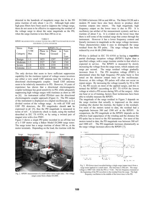
ns [6]. An instrument called PDAlert uses the directional<br />
electromagnetic coupler approach (Figure 2). The PD output<br />
<strong>of</strong> the instrument is displayed on a digital oscilloscope, as is a<br />
divided version <strong>of</strong> the voltage surge. As with all VHF and<br />
UHF PD detectors, the PD magnitudes should not be<br />
expressed in pC [5], thus the PD magnitude is measured in<br />
terms <strong>of</strong> mV. A sensitivity check is made, using the method<br />
described in IEC TS 61934, or by using a twisted pair <strong>of</strong><br />
magnet wire with a low PDIV.<br />
Figure 3 shows a single PD pulse recorded in an <strong>of</strong>f-line test<br />
<strong>of</strong> a 5 HP motor using a Baker Model D12000 surge tester.<br />
The surge tester has a surge risetime <strong>of</strong> about 100 ns, at the<br />
motor terminals. Depending on the load, the risetime with the<br />
D12000 is between 100 ns and 400 ns. The Baker D12R and a<br />
modern PJ tester have also been shown to produce short<br />
risetime outputs into stators. The high magnitude, high<br />
frequency output on the lower trace is due to PD. It is<br />
oscillatory (an artifact <strong>of</strong> the measurement system), and has a<br />
risetime <strong>of</strong> about 5 ns. It is evident on the lower trace that<br />
there is still some <strong>of</strong> the residual surge that comes through the<br />
instrument. However it has a lower frequency content and<br />
linearly increases in magnitude as the surge voltage increases.<br />
These characteristics make it easy to distinguish the surge<br />
residual from the PD pulse. The surge voltage has been<br />
reduced by over 66 db (2000 times).<br />
PD-free is defined in IEC TS 61934 as having a repetitive<br />
partial discharge inception voltage (RPDIV) higher than a<br />
specified voltage, with a surge risetime similar to that which is<br />
expected in service. The RPDIV is measured by slowly<br />
increasing the voltage from the surge tester, which outputs one<br />
surge per second. The surge residual voltage gradually<br />
increases from 0. The PD inception voltage (PDIV) is<br />
determined when the high frequency PD pulse burst is first<br />
noted on the detector output trace on the oscilloscope.<br />
However, at this voltage, PD pulses will <strong>of</strong>ten not occur on<br />
repeat surges. By increasing the voltage (usually by 50 to 300<br />
V), the PD occurs on most <strong>of</strong> the applied surges, and this is<br />
termed the RPDIV (according to IEC TS 61934 the lowest<br />
voltage at which a PD occurs during 50% <strong>of</strong> the surges). After<br />
one hour or so <strong>of</strong> training, factory floor technicians have been<br />
able to reliably measure the RPDIV.<br />
The magnitude <strong>of</strong> the surge residual in Figure 3 depends on<br />
the surge risetime that actually is impressed on the stator<br />
winding (the shorter the risetime, the higher is the residual).<br />
For most <strong>of</strong> the motors tested to date, the residual had a<br />
magnitude between 500 and 1500 mV at the RPDIV. In<br />
comparison, the PD magnitude at the RPDIV depends on the<br />
effective load capacitance <strong>of</strong> the winding and the distance the<br />
PD pulse has to travel to the PD instrument. For most <strong>of</strong> the<br />
motors tested to date, the PD magnitude was between 300 mV<br />
and 1000 mV. The PD magnitude increases dramatically as<br />
the surge voltage increases above the RPDIV [7].<br />
Scope<br />
Surge generator<br />
PD detector<br />
Stator<br />
Fig. 2. RPDIV measurement <strong>of</strong> a small motor stator (right side). The voltage<br />
surges come from a Baker D12000.<br />
Fig. 3. PD (lower trace) recorded during a single surge (upper trace) from a<br />
surge tester applied to a small stator. The time base is 50ns.div. The surge<br />
voltage is 1000 V/div while the PD is 1 V/div. The low frequency transient at<br />
the beginning <strong>of</strong> the PD waveform is the residual from the surge. The high<br />
frequency oscillation in the middle <strong>of</strong> the lower trace is the PD.<br />
189