Partial Discharge Testing of Random Wound Stators ... - IEEE Xplore
Partial Discharge Testing of Random Wound Stators ... - IEEE Xplore
Partial Discharge Testing of Random Wound Stators ... - IEEE Xplore
You also want an ePaper? Increase the reach of your titles
YUMPU automatically turns print PDFs into web optimized ePapers that Google loves.
2009 <strong>IEEE</strong> Electrical Insulation Conference, Montreal, QC, Canada, 31 May - 3 June 2009<br />
<strong>Partial</strong> <strong>Discharge</strong> <strong>Testing</strong> <strong>of</strong> <strong>Random</strong> <strong>Wound</strong> <strong>Stators</strong><br />
During Short Risetime Voltage Surges<br />
G.C. Stone (F<strong>IEEE</strong>) and I. Culbert (SM<strong>IEEE</strong>)<br />
Iris Power LP<br />
3110 American Drive<br />
Mississauga, ON, Canada L4V 1T2<br />
Abstract: Modern inverter fed motors <strong>of</strong>ten produce short<br />
risetime, high magnitude voltage surges that may lead to partial<br />
discharge in the random wound stator windings. Detection <strong>of</strong> PD<br />
during such voltage surges can not be done with the usual PD<br />
detectors described by ASTM D1868. Instead a detector that can<br />
separate PD pulse currents from a short risetime voltage surge is<br />
required. This paper describes a PD detector that can measure<br />
PD pulses when the applied voltage is a voltage surge with a<br />
risetime as short as 100 ns. PD data has been collected from<br />
dozens <strong>of</strong> stators, many <strong>of</strong> which had known insulation problems.<br />
In most cases the PDIV easily met the requirements <strong>of</strong> a new IEC<br />
technical specification that sets the partial discharge inception<br />
voltages for random wound stators. Since most <strong>of</strong> these stators<br />
had obvious insulation system deficiencies, it seems that the<br />
PDIV levels set by IEC TS 60034-18-41 may be too low.<br />
(PD) [1-3]. Since the magnet wire insulation is primarily<br />
made from organic materials, if sufficient PD activity occurs,<br />
the insulation deteriorates and eventually fails. Thus it is<br />
usually desired that no PD occurs during operation <strong>of</strong> the<br />
motors. IEC TS 60034-18-41 sets the minimum voltages that<br />
PD may occur (Table 1).<br />
This paper discusses how the PD can be measured during<br />
short risetime voltage surges, and presents some PD data<br />
measured on many stators during short risetime surges.<br />
I. INTRODUCTION<br />
Variable speed drives <strong>of</strong> the voltage source, pulse width<br />
modulation type have become one <strong>of</strong> the most popular types<br />
<strong>of</strong> motor drives. Such drives can produce switching voltage<br />
surges with a risetime as short as 100 ns, and with thousands<br />
<strong>of</strong> surges per second [1]. There is anecdotal evidence that the<br />
large number <strong>of</strong> voltage surges from such inverter fed drives<br />
(IFDs) may lead to the deterioration and eventual failure <strong>of</strong> the<br />
insulation in low voltage (less than 1000 V) motor stator<br />
windings [1-4]. Surges over 3000 V and risetimes as short as<br />
100 ns have been measured on motors that are nominally rated<br />
up to 690 Vrms (phase to phase) [3].<br />
The stator windings are “random wound” in most motors rated<br />
less than 1000 V. This implies that the magnet wire connected<br />
to the phase terminals in one phase, may be adjacent to<br />
magnet wire in another phase or a magnet wire near the<br />
neutral. In addition, for short risetime pulses, the voltage is<br />
not uniformly distributed from the phase terminal down to<br />
neutral. Instead, most <strong>of</strong> the voltage is dropped across the<br />
turns at the line –end <strong>of</strong> the winding [2]. As a result,<br />
unusually high voltages can occur across adjacent turns <strong>of</strong><br />
magnet wire; between magnet wires in different phases; and<br />
between the magnet wire and the grounded stator slot.<br />
The electrical stresses may be high due to these voltages, the<br />
relatively small diameter <strong>of</strong> the magnet wire and the thinness<br />
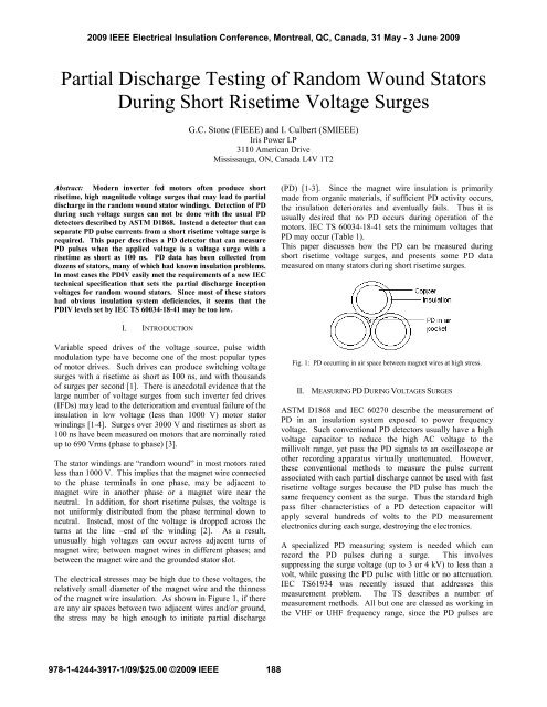
<strong>of</strong> the magnet wire insulation. As shown in Figure 1, if there<br />
are any air spaces between two adjacent wires and/or ground,<br />
the stress may be high enough to initiate partial discharge<br />
Fig. 1: PD occurring in air space between magnet wires at high stress.<br />
II. MEASURING PD DURING VOLTAGES SURGES<br />
ASTM D1868 and IEC 60270 describe the measurement <strong>of</strong><br />
PD in an insulation system exposed to power frequency<br />
voltage. Such conventional PD detectors usually have a high<br />
voltage capacitor to reduce the high AC voltage to the<br />
millivolt range, yet pass the PD signals to an oscilloscope or<br />
other recording apparatus virtually unattenuated. However,<br />
these conventional methods to measure the pulse current<br />
associated with each partial discharge cannot be used with fast<br />
risetime voltage surges because the PD pulse has much the<br />
same frequency content as the surge. Thus the standard high<br />
pass filter characteristics <strong>of</strong> a PD detection capacitor will<br />
apply several hundreds <strong>of</strong> volts to the PD measurement<br />
electronics during each surge, destroying the electronics.<br />
A specialized PD measuring system is needed which can<br />
record the PD pulses during a surge. This involves<br />
suppressing the surge voltage (up to 3 or 4 kV) to less than a<br />
volt, while passing the PD pulse with little or no attenuation.<br />
IEC TS61934 was recently issued that addresses this<br />
measurement problem. The TS describes a number <strong>of</strong><br />
measurement methods. All but one are classed as working in<br />
the VHF or UHF frequency range, since the PD pulses are<br />
978-1-4244-3917-1/09/$25.00 ©2009 <strong>IEEE</strong><br />
188
detected in the hundreds <strong>of</strong> megahertz range due to the PD<br />
pulse risetime <strong>of</strong> only about 1 ns [5]. Although high order<br />
high pass filters have been used to suppress the voltage surge,<br />
these do not seem to be effective in suppressing the residual <strong>of</strong><br />
the voltage surge to about the same magnitude as the PD,<br />
when the surge risetime is less than 200 ns or so.<br />
TABLE I<br />
RPDIV MEASURED WITH A SURGE TESTER FOR A 480 V RATED MOTOR STATOR<br />
FED FROM A 2 LEVEL INVERTER<br />
Stress<br />
Category<br />
Peak<br />
V/DC<br />
Bus<br />
RPDIV (V p-p )<br />
Phase to Phase to<br />
Phase Ground<br />
Turn<br />
to<br />
Turn<br />
Benign 1.1 1853 1297 1297<br />
Moderate 1.5 2527 1769 1769<br />
Severe 2.0 3370 2359 2359<br />
Extreme 2.5 4212 2948 2948<br />
The only devices that seem to have sufficient suppression<br />
capability for the risetimes typical <strong>of</strong> voltage source invertors<br />
use either a very small UHF antenna near the winding or a<br />
directional electromagnetic coupler. Small UHF antennae<br />
seem to be relatively insensitive to PD. However, 10 years <strong>of</strong><br />
experience has shown that a directional electromagnetic<br />
coupler technique has good sensitivity to PD, while adequately<br />
suppressing high voltage surges with risetimes as short as 100<br />
ns [6]. An instrument called PDAlert uses the directional<br />
electromagnetic coupler approach (Figure 2). The PD output<br />
<strong>of</strong> the instrument is displayed on a digital oscilloscope, as is a<br />
divided version <strong>of</strong> the voltage surge. As with all VHF and<br />
UHF PD detectors, the PD magnitudes should not be<br />
expressed in pC [5], thus the PD magnitude is measured in<br />
terms <strong>of</strong> mV. A sensitivity check is made, using the method<br />
described in IEC TS 61934, or by using a twisted pair <strong>of</strong><br />
magnet wire with a low PDIV.<br />
Figure 3 shows a single PD pulse recorded in an <strong>of</strong>f-line test<br />
<strong>of</strong> a 5 HP motor using a Baker Model D12000 surge tester.<br />
The surge tester has a surge risetime <strong>of</strong> about 100 ns, at the<br />
motor terminals. Depending on the load, the risetime with the<br />
D12000 is between 100 ns and 400 ns. The Baker D12R and a<br />
modern PJ tester have also been shown to produce short<br />
risetime outputs into stators. The high magnitude, high<br />
frequency output on the lower trace is due to PD. It is<br />
oscillatory (an artifact <strong>of</strong> the measurement system), and has a<br />
risetime <strong>of</strong> about 5 ns. It is evident on the lower trace that<br />
there is still some <strong>of</strong> the residual surge that comes through the<br />
instrument. However it has a lower frequency content and<br />
linearly increases in magnitude as the surge voltage increases.<br />
These characteristics make it easy to distinguish the surge<br />
residual from the PD pulse. The surge voltage has been<br />
reduced by over 66 db (2000 times).<br />
PD-free is defined in IEC TS 61934 as having a repetitive<br />
partial discharge inception voltage (RPDIV) higher than a<br />
specified voltage, with a surge risetime similar to that which is<br />
expected in service. The RPDIV is measured by slowly<br />
increasing the voltage from the surge tester, which outputs one<br />
surge per second. The surge residual voltage gradually<br />
increases from 0. The PD inception voltage (PDIV) is<br />
determined when the high frequency PD pulse burst is first<br />
noted on the detector output trace on the oscilloscope.<br />
However, at this voltage, PD pulses will <strong>of</strong>ten not occur on<br />
repeat surges. By increasing the voltage (usually by 50 to 300<br />
V), the PD occurs on most <strong>of</strong> the applied surges, and this is<br />
termed the RPDIV (according to IEC TS 61934 the lowest<br />
voltage at which a PD occurs during 50% <strong>of</strong> the surges). After<br />
one hour or so <strong>of</strong> training, factory floor technicians have been<br />
able to reliably measure the RPDIV.<br />
The magnitude <strong>of</strong> the surge residual in Figure 3 depends on<br />
the surge risetime that actually is impressed on the stator<br />
winding (the shorter the risetime, the higher is the residual).<br />
For most <strong>of</strong> the motors tested to date, the residual had a<br />
magnitude between 500 and 1500 mV at the RPDIV. In<br />
comparison, the PD magnitude at the RPDIV depends on the<br />
effective load capacitance <strong>of</strong> the winding and the distance the<br />
PD pulse has to travel to the PD instrument. For most <strong>of</strong> the<br />
motors tested to date, the PD magnitude was between 300 mV<br />
and 1000 mV. The PD magnitude increases dramatically as<br />
the surge voltage increases above the RPDIV [7].<br />
Scope<br />
Surge generator<br />
PD detector<br />
Stator<br />
Fig. 2. RPDIV measurement <strong>of</strong> a small motor stator (right side). The voltage<br />
surges come from a Baker D12000.<br />
Fig. 3. PD (lower trace) recorded during a single surge (upper trace) from a<br />
surge tester applied to a small stator. The time base is 50ns.div. The surge<br />
voltage is 1000 V/div while the PD is 1 V/div. The low frequency transient at<br />
the beginning <strong>of</strong> the PD waveform is the residual from the surge. The high<br />
frequency oscillation in the middle <strong>of</strong> the lower trace is the PD.<br />
189
III. EXPERIMENTAL PD DATA<br />
The RPDIV has now been measured on over 100 stators, and<br />
the data formally recorded from 39 machines. Table 2 shows a<br />
summary <strong>of</strong> the RPDIV collected by ourselves using either a<br />
D12R or a D12000 surge tester. The test objects were all<br />
stator windings, rated from 1 HP to 6400 HP and from 380 V<br />
to 690 V. Almost all were random wound stators. Most <strong>of</strong> the<br />
measurements in Table 2 occurred because the motor OEM or<br />
the enduser had experienced premature stator winding<br />
insulation failures, and PD due to IFD voltage surges was one<br />
<strong>of</strong> the possible failure mechanisms.<br />
The measured surge risetime was from 150 to 400 ns, and the<br />
surge pulse width for most stators ranged from 10 to 40 μs,<br />
with a slow fall-time. Due to the long width and slow fall, and<br />
since the opposite polarity undershoot was always less than<br />
25% <strong>of</strong> the peak surge magnitude, the RPDIV is measured<br />
from 0V to the peak, as suggested in IEC TS 60034-18-41<br />
(Table B.2, Column 6, Note b). This is valid for the turn to<br />
turn RPDIV. Example minimum RPDIVs are shown in Table<br />
1. The phase to ground RPDIV may be as much as 25%<br />
higher than shown in Table 2.<br />
The second last column shown in Table 2 is the lowest RPDIV<br />
measured on all phases and with all possible test connections<br />
in 39 stators. The PD may be occurring between turns,<br />
between a phase and ground, or in the endwinding between<br />
phases. If the RPDIV is indicated with “>”, the RPDIV was<br />
not measured since the motor owner did not want to exceed<br />
the indicated voltage. The measured RPDIVs can be<br />
compared the minimum required RPDIV for a “moderate” and<br />
“severe” surge environment in columns 4 and 5, as defined in<br />
the IEC TS.<br />
TABLE II<br />
MEASURED PHASE TO GROUND AND TURN TO TURN RPDIV COMPARED TO THE MINIMUM REQUIRED RPDIV FOR THE MODERATE<br />
AND SEVERE STRESS CATEGORIES.<br />
Rating DC Bus Min. Turn or Ground Measured<br />
Condition<br />
RPDIV (Volts) Min. PDIV<br />
HP Volts Volts Moderate Severe Volts<br />
1 440 590 1593 2124 1900<br />
10 440 590 1593 2124 2200<br />
20 440 590 1593 2124 1800<br />
650 440 590 1593 2124 1250<br />
650 440 590 1593 2124 2080<br />
1100 690 975 2632 3510 1352 Failed<br />
170 690 975 2632 3510 983 Failed<br />
6400 1287 1600 Failed (tr 500 ns)<br />
880 600 850 2295 3060 2200<br />
300 600 850 2295 3060 2200 Failed<br />
300 600 850 2295 3060 >2500<br />
300 600 850 2295 3060 >2500<br />
300 600 850 2295 3060 >2500<br />
300 600 850 2295 3060 >2500<br />
880 600 850 2295 3060 1890 Cast, cracks<br />
950 600 850 2295 3060 1240 No phase insulation<br />
880 600 850 2295 3060 >2600<br />
950 600 850 2295 3060 >2400<br />
950 600 850 2295 3060 >2600<br />
880 600 850 2295 3060 2320 Contaminated<br />
1000 690 975 2632 3510 >2000<br />
1000 690 975 2632 3510 2600<br />
1000 690 975 2632 3510 >2000<br />
17 415 560 1512 2016 2960<br />
17 415 560 1512 2016 2160 No phase insulation<br />
35 415 560 1512 2016 2640<br />
35 380 513 1385 1847 2480<br />
35 380 513 1385 1847 2960<br />
17 380 513 1385 1847 2240<br />
17 380 513 1385 1847 2560<br />
17 380 513 1385 1847 2320<br />
36 380 513 1385 1847 2720<br />
17 380 513 1385 1847 1400 Failed<br />
17 380 513 1385 1847 1900 Poor impregnation<br />
17 380 513 1385 1847 1400 Poor impregnation<br />
350 440 590 1593 2124 >2000 Similar motors failed<br />
350 440 590 1593 2124 >2000 Similar motors failed<br />
350 440 590 1593 2124 2700 Similar motors failed<br />
350 440 590 1593 2124 3100 Similar motors failed<br />
190
Some observations on these results are:<br />
• 4 stators with known problems exceeded the<br />
“severe” level, and thus the level set for the severe<br />
level seems to be too low for these stators since the<br />
“bad” windings still would have passed.<br />
• 9 <strong>of</strong> the 39 stators with known problems had<br />
RPDIVs that exceeded the moderate level. Thus<br />
these motors would have passed a moderate severity<br />
RPDIV test, even with the known problems. Of<br />
course none <strong>of</strong> the motors were originally qualified<br />
to the new IEC TS, since most <strong>of</strong> the motors predate<br />
the TS. Thus we do not know the stress category<br />
the motors were designed for.<br />
• The RPDIVs range from 1000 V to 3000 V (for all<br />
voltage ratings). For motors <strong>of</strong> one voltage rating<br />
(say 440 V), the RPDIV ranged from 1250 V to<br />
3100 V. Clearly there is a great difference in<br />
RPDIVs between stators, and presumably a great<br />
difference in design, manufacturing and<br />
impregnation.<br />
Data published by GE on 18 motors <strong>of</strong> the same rating from<br />
6 manufacturers also showed high variability in the RPDIV –<br />
ranging from 1600 V to 3200 V [8]. GE also reported that in<br />
factory tests on 2088 motors rated 440V, the PD ranged from<br />
2950 V to 3690 V [8]. All <strong>of</strong> these motors easily passed the<br />
RPDIV acceptance requirement for a “severe” insulation<br />
environment.<br />
IV. CONCLUSIONS<br />
1. A new IEC technical specification has been issued which<br />
sets the minimum PD inception voltages for inverter fed<br />
motors, based on the expected severity <strong>of</strong> the voltage surges<br />
at the motor terminals.<br />
2. PD measurement equipment that is capable <strong>of</strong> separating<br />
PD from the relatively large applied voltage surges has been<br />
in commercial use for 10 years. This PD detector will<br />
separate PD from the surges for surge risetimes as short as<br />
100 ns – which is the risetime <strong>of</strong> surges that can occur from<br />
IFDs. At least two OEMs use the detector routinely on the<br />
factory floor to ensure production motors have a suitably<br />
high RPDIV.<br />
3. Separating the PD from the various sources (turn, ground<br />
and interphasal insulation) is not trivial. In addition to<br />
measuring the PD under surges, it is useful to also measure<br />
the PD with 50/60 Hz AC voltage applied to the windings.<br />
This will help to separate turn to turn PD (which only occurs<br />
with surge voltages) from ground and interphasal PD (AC<br />
will only excite ground and interphasal PD).<br />
4. Production motor acceptance testing by others shows the<br />
RPDIV easily exceeds the IEC TS 60034-18-41 requirements<br />
for Type I insulation systems, thus indicating that perhaps the<br />
minimum RPDIV levels that have been established are too<br />
low. This is further supported by the 39 stators reported<br />
here, since some <strong>of</strong> the motors which had known<br />
deficiencies, also passed the current minimum levels.<br />
REFERENCES<br />
[1] Persson, E. ‘Transient Effects in Applications <strong>of</strong> PWM Inverters to<br />
Induction Motors’, <strong>IEEE</strong> Trans IAS, Sept 1992, p1095.<br />
[2] Stone, G.C., et al, “Electrical Insulation for Rotating Machines”, Wiley<br />
<strong>IEEE</strong> Press, 2004<br />
[3] Stone, G.C., Campbell, S., Tetreault, S. “Invertor Fed Drives: Which<br />
Motor <strong>Stators</strong> are at Risk”, <strong>IEEE</strong> Industry Applications Magazine, Sept<br />
2000, pp17.<br />
[4] Wheeler, J., “Effects <strong>of</strong> Converter Pulses on Electrical Insulation – The<br />
New IEC Technical Specification”, <strong>IEEE</strong> Electrical Insulation<br />
Magazine, Mar 2005, p22.<br />
[5] S. Coen et al, “Sensitivity to UHF PD in Power Transformers”, <strong>IEEE</strong><br />
Trans DEIS, Dec 2008, p1553.<br />
[6] Stone, G.C., Campbell, S., Susnik, M. “New Tools to Determine the<br />
Vulnerability <strong>of</strong> Stator Windings to Voltage Surges from IFDs”, Proc.<br />
<strong>IEEE</strong> Electrical Insulation Conference, Cincinnati, October 1999,<br />
p149.<br />
[7] Fenger, M., Stone, G.C., “Progress in Understanding the Nature <strong>of</strong> PD<br />
in <strong>Stators</strong> Created by Inverter Drives”, Proc. <strong>IEEE</strong> Electrical Insulation<br />
Conference, Sept 2003, p363.<br />
[8] Bogh, D, et al, “<strong>Partial</strong> <strong>Discharge</strong> Inception <strong>Testing</strong> on Low Voltage<br />
Motors”, <strong>IEEE</strong> Trans IA, Jan 2006, p148.<br />
191


