TES EnergyFaçade â prefabricated timber based building system for ...
TES EnergyFaçade â prefabricated timber based building system for ...
TES EnergyFaçade â prefabricated timber based building system for ...

You also want an ePaper? Increase the reach of your titles
YUMPU automatically turns print PDFs into web optimized ePapers that Google loves.
<strong>TES</strong> EnergyFaçade –<br />
<strong>prefabricated</strong> <strong>timber</strong> <strong>based</strong> <strong>building</strong> <strong>system</strong><br />
<strong>for</strong> improving the energy efficiency of the<br />
<strong>building</strong> envelope<br />
funded by:<br />
Woodwisdom Net<br />
Research project from 2008-2009
<strong>TES</strong> EnergyFaçade 0_2<br />
Content<br />
1.1. Modernisation - the 2nd chance <strong>for</strong> architecture 19<br />
1.2. <strong>TES</strong> method - Systemised workflow 23<br />
2. Building stock 31<br />
2.1. Energy efficiency in Building Stock 36<br />
2.2. Resource Efficiency in Building Stock 38<br />
2.3. Systemisation 40<br />
2.3.1. Building geometry 41<br />
2.3.2. Foundation 42<br />
2.3.3. Exterior wall 46<br />
2.3.4. Window 50<br />
2.3.5. Ceiling / balcony 56<br />
3. <strong>TES</strong> Method 60<br />
3.1. Survey and Digital Workflow 64<br />
3.1.1. Economic survey 67<br />
3.1.2. Methods of geometrical <strong>building</strong> survey 68<br />
3.1.3. 3D Laser-scanning <strong>for</strong> <strong>TES</strong> projects: possibilities and challenges 74<br />
3.1.4. Reality versus model: Accuracy / Tolerances 76<br />
3.1.5. Digital Workflow 78<br />
3.1.6. Case study of a façade survey 85<br />
3.2. Environmental Impact and Life Cycle 88<br />
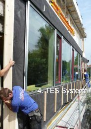
4. <strong>TES</strong> System 98<br />
4.1. <strong>TES</strong> Element 100<br />
4.1.1. Form and Function 104<br />
4.1.2. Adaption layer 107<br />
4.1.3. Windows 114<br />
4.2. Mounting and Fixation 120<br />
4.2.1. Mounting 120<br />
4.2.2. Load Bearing 121<br />
4.2.3. Element façades fixation joints 125<br />
4.3. Building Physics 127<br />
4.3.1. Fire Safety of Façades 127<br />
4.3.2. Hygrothermal (Heat, Air, Moisture) and Air / Wind Tightness 135<br />
4.3.3. Cavities in adaption layer and drying potential in existing wet walls 143<br />
4.3.4. Acoustics (Sound Protection) 146<br />
4.4. Building services 148<br />
5. Quality assurance 156<br />
5.1. Regulations 157<br />
5.2. <strong>TES</strong> specification 158<br />
5.3. Design recommendations <strong>for</strong> <strong>TES</strong> EnergyFaçade 159<br />
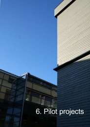
6. Pilot Projects in Europe 164<br />
6.1. Realschule, Buchloe, Germany 165<br />
6.2. Technical College, Risør, Norway 173<br />
6.3. Student Housing, Oulu, Finland 185
<strong>TES</strong> EnergyFaçade 0_3<br />
Graphics and Pictures<br />
1. Modernisation workflow 19<br />
2. <strong>TES</strong> EnergyFaçade <strong>building</strong> method. 19<br />
3. Global warming map, © by NASA. 20<br />
4. Possible interventions 22<br />
5. Schwanenstadt, AustriaSchool be<strong>for</strong>e and after modernisation; PAUAT Architekten, 2004 23<br />
6. Risør College, NorwayPrefabricated façade elements with close boarding, assembled in 2009. 23<br />
7. Retrofit interventions <strong>for</strong> energy efficiency. 24<br />
8. Prefabricated façade element assembly at Realschule Buchloe. 25<br />
9. Simplified lifecycle model of a <strong>TES</strong> EnergyFacade retrofit. 26<br />
10. Wide variety of surface solutions <strong>for</strong> <strong>TES</strong>. 28<br />
11. Residential units by <strong>building</strong> age class, Germany. 32<br />
12. Typical appartment houses of the post war era. 33<br />
13. Typology of relevant <strong>building</strong> types. 34<br />
14. Typological floor plans with corridor houses and terraced houses (from left t. r.): acc. to Neufert, 1973. 35<br />
15. Typological floor plans with centralised access (from left t. r.): double dwelling, triple dwelling, staggered dwelling,<br />
Point block, acc. t. Neufert, 1973. 35<br />
16. Examples of German dwellings from the 60s and 70s in Nuremberg. 35<br />
17. Building stock clustered in <strong>building</strong> age classes and its specific heat energy demand. 36<br />
18. Type of heating <strong>system</strong> in residential units in millions. 37<br />
19. Load bearing outer walls versus a skeleton structure with infill. 40<br />
20. Base with cellar window 42<br />
21. Window and light shaft, DH Weissenseestraße, Augsburg 42<br />
22. Raised ground floor, MFH Hinterbärenbadstraße , München 43<br />
23. Flat terrain. 43<br />
24. Tilted terrain. 43<br />
25. Separate foundation 44<br />
27. Fixation of brackets, Realschule Buchloe, 08/2009 44<br />
26. Bracket at ceiling edge 44<br />
28. Single layered masonry 46<br />
29. Insulated sandwich element 46<br />
30. Ventilated structure 46<br />
31. Principle heat transmission 47<br />
32. Isotherm curve of an uninsulated exterior corner. Temperature on the surface inside is below the critical Temperature<br />
of 12,6 °C. 47<br />
34. Joint in concrete skeleton structure 48<br />
33. Façade joints in existing constructions. 48<br />
35. Heat bridge at roof eves: no heat bridge or a negligible geometric one (left), on the right there is a constructional<br />
heat bridge remaining. 49<br />
36. Inner stop against outer reveal projection 50<br />
37. Outer stop against inner reveal projection 50<br />
38. Flat connection to reveal 50<br />
39. Situation interior against façade columns 50<br />
40. Situation in front of façade columns 50<br />
41. Flat connection between columns 50<br />
42. Interior rolling shutter box and radiator niche, brick masonry 30 cm, D-Augsburg 53<br />
44. Double layered brick masonry with <strong>timber</strong> framed window element, 10 cm, poor insulation standard, NL-Roosendaal<br />
53
<strong>TES</strong> EnergyFaçade 0_4<br />
43. Exterior shutter box, D-Augsburg 53<br />
45. Curtain wall at stair case, loggia with additional glazing <strong>for</strong> noise protection, D-Augsburg 53<br />
46. Spandrel panel ribbon glazing 54<br />
47. Window, aluminium flat against reveal and parapet. 54<br />
48. Window sill, cable channel and radiator in front off parapet. D-München, Umweltamt 54<br />
49. Exterior structural glazing façade with rotating tilting frames, sun shading device, D-Buchloe, Realschule 54<br />
50. Timber frame wall with poor insulation, large window areas, NOR- Rsior, College 55<br />
52. Ceiling and balcony constructions. 56<br />
51. Two types of exterior wall construction. 56<br />
53. Cantilevering slab 57<br />
55. Partly cantilevered slab 57<br />
54. Loggia 57<br />
56. Balcony 57<br />
57. Cutting off balcony slab 58<br />
58. <strong>TES</strong> process diagram. 60<br />
60. Prefabrication degrees 62<br />
59. Prefabrication and installation process. 62<br />
61. Comprehensive inspection of a property. 64<br />
62. The <strong>prefabricated</strong> <strong>TES</strong> element has to fit on the existing façade like a stencil. 65<br />
63. Irregularities of a façade with a size of around 32 x 9 m. The maximum deviation perpendicular to the surface<br />
plane is in total between 30 and 40 mm. 65<br />
64. Example Rotlintstrstrasse, Frankfurt, Germany. A typical post-war <strong>building</strong> from the early 1950s. 66<br />
65. Influencing parameters on several measuring methods used in façade survey (close to centre is not recommended).<br />
Hand measuring is mentioned <strong>for</strong> comparison, but it is not competitive as it lacks 3D properties. 67<br />
66. Benefit-cost ratio of the used measuring methods. Source Rauch 2008. 68<br />
67. Typical application of a reverse engineering process with uneven surfaces in dental technology. 69<br />
68. Multi-image 3D photogrammetry - postprocessing / 3D modeling of discreet façade points. 69<br />
69. A modern Tacheometer also called Totalstation. 70<br />
70. Full featured 360° 3D Laserscanner on a tripod. 70<br />
71. Entire raw data model consisting of a registered and cleaned point cloud, taken by a 3D laserscan. 71<br />
72. Critical points of a façade survey. 76<br />
73. 3D model of the <strong>timber</strong> fabricator providing the façade <strong>for</strong> Realschule Buchloe, produced in july and assembled<br />
in august 2009. 80<br />
74. 3D wireframe model of the Realschule Buchloe was basis <strong>for</strong> the product model of the <strong>timber</strong> fabricator, surveyed<br />
in june 2009. 81<br />
75. Step by step development of a product model (BIM) from survey data. 82<br />
76. Necessary steps of a <strong>TES</strong> survey campaign <strong>based</strong> on Scherer’s paradigm. 83<br />
77. (a) Definition of a façade plane, (b) insertion of volumetric solids in the position of a window opening, (c) collision<br />
control between pointcloud and solid. Continuation of the iterative process by further adjustment and collision<br />
control. 84<br />
78. Criteria and relation cost - complexity of 3D models. 84<br />
79. Case study <strong>building</strong> from the 1950s located in Frankfurt, Germany. 85<br />
80. 3D Wireframe model of Rotlinstraße, Frankfurt. 85<br />
81. 3D parametric model in SEMA after importing and postprocessing the wireframe model. 85<br />
82. Rectified image (left) and digital surface model (DSM) of the façade (right), showing the topography in different<br />
colours (deviation to perpendicular to reference plane - each colour corresponds a 5 mm step in height). 87<br />
84. The three pillars analogy of sustainability. 88<br />
83. Product life cycle of <strong>TES</strong> EnergyFaçade. The main construction material is mainly <strong>timber</strong> <strong>based</strong> and can be<br />
reused or easily recycled at its end of life. 88<br />
85. System borders <strong>for</strong> sustainability and LCA of <strong>TES</strong>. 89
<strong>TES</strong> EnergyFaçade 0_5<br />
87. Lifecycle of an entire <strong>building</strong> and lifecycle of modernisation products. 90<br />
86. Concept of description of sustainability due to CEN / TC 350 as basis <strong>for</strong> the EN 15643. 90<br />
88. Typical technical lifetime of different façade modernisation <strong>system</strong>s and the related eco-indicator 99. 91<br />
89. Specification of different insulation materials concerning heat conductivitiy and primary energy intensity (nonrenewable).<br />
The thicknesses of insulation is standardized to a U-value of 0,2 kWh/m2 in this case. The red boxes<br />
show the contained primary energy (PEI) per m2. The data is <strong>based</strong> on the Ökobau.dat delivered by German Federal<br />
Ministry of Construction. 92<br />
91. Basic <strong>TES</strong> application and <strong>system</strong> hierarchy with; a) existing structure, b) adaption layer, c) <strong>timber</strong> framework<br />
and insulation as main layer, d) cladding layer on the exterior side. 98<br />
92. Variation of cladding materials in combination with a <strong>TES</strong> basic element. 99<br />
93. Variation in size and orientation of <strong>TES</strong> elements. 100<br />
94. Basic <strong>TES</strong> element with a) insulation b) panelling and c) structure. 101<br />
95. Different <strong>TES</strong> structure compositions <strong>based</strong> on the same principle of a framed wall element. 102<br />
96. Elements <strong>for</strong> Realschule Buchloe. 105<br />
97. Horizontal and vertical division - spatial enclosure and extension. 105<br />
98. Self-supporting structure with own foundation and roof extension (left), partly suspended structure (right). 106<br />
99. Ceiling slabs able to take loads in each storey. 106<br />
100. Basics concept of an element-façade 106<br />
101. Fixation of adaption layer on the existing wall. Depicted here is a Heraklith surface, Realschule Buchloe 107<br />
102. Element joint at sill 107<br />
103. Overview entire test assembly. Left a two storey and right a small sized, single storey element. 108<br />
104. Element edges and their sealing. 108<br />
105. Drawing of the two storey element. 109<br />
106. Drawing of small element. 110<br />
107. Window sill and reveal with sealing. 111<br />
109. Trailer <strong>based</strong> standard ISOBLOW station. 111<br />
108. Insulation per<strong>for</strong>ated by hose 111<br />
110. Filling procedure 111<br />
111. Hole <strong>for</strong> control of filling 112<br />
112. Joints seald with PU foam. 112<br />
113. Drilled hole <strong>for</strong> filling hose. 112<br />
114. Dust emission through boreholes. 113<br />
115. Control opening:Cellulose fibre filling (bottom) andSLS filling (top) 113<br />
116. Elevation, vertical and horizontal section of a basic <strong>TES</strong> structure and layering. 114<br />
117. Distribution of illuminance values. 115<br />
118. Rendered interior view of a room with one window and deep reveals. 115<br />
119. Window replacement in masonry wall construction. New window is fully integrated in insulation layer. 116<br />
120. Conservation of existing window and an additional exterior window integrated in the insulation layer. 117<br />
121. Enlargement of existing window geometry (french window). 118<br />
123. Airtight joint at window reveal with a double layer gypsum fibre board 119<br />
122. Vertical section window lintel with air-tight sealing of the gap (adaption layer). 119<br />
124. Precise adjustment of edge beam <strong>for</strong> fixation of elements. 120<br />
125. Distance of scaffolding <strong>for</strong> mounting purpose. 120<br />
126. Operating range of crane and other liftung devices. 120<br />
127. Different lifting equipment with mobile crane etc. 120<br />
128. Lifting solution <strong>for</strong> façade elements beneath roof overhang or structured façades, balconies etc. Developed<br />
by O.LUX, Georgensgmünd 120<br />
129. Supports of <strong>TES</strong> element. 121<br />
130. Loads on <strong>TES</strong> element. 121
<strong>TES</strong> EnergyFaçade 0_6<br />
131. Typology of mounting elements a) hanging, b) storey wise mounted, c) standing, d) storey wise standing. 121<br />
132. Load bearing survey process. 122<br />
134. Pull test at an existing concrete wall. 123<br />
135. Adhesive anchors <strong>for</strong> concrete or masonry walls. 123<br />
133. Existing condition analysis. 123<br />
136. L- bracket with a sill beam.Exchange of brick layer in front of the ceiling, grouting closer. 124<br />
137. Cantilever beame.g. IPE rocker. Fixation under basement ceiling, grouting closer 124<br />
138. FoundationPrecast concrete component, frost resistance founded, adaption layer thermal insulation. 124<br />
139. Fixation possibilities of <strong>TES</strong> modules a) puncti<strong>for</strong>m support b) linear horizontal supp. c) linear vertical supp. d)<br />
hinge fixation 125<br />
140. Different types of elements joints and sealing solutions. 126<br />
141. Fire scenarios <strong>for</strong> <strong>TES</strong> façade and ciritical joints (red circles). 127<br />
142. Building and façade structure of existing <strong>building</strong>s a) punctuated monolithic wall structure b) skeleton structure<br />
c) crosswall structure. 128<br />
144. <strong>TES</strong> EnergyFaçade assembly with panelling and insulation <strong>for</strong> EI30 (grey). Horizontal fire stops (blue) <strong>for</strong><br />
ventilated gaps of façade and floorwise separation of stacked windows. 129<br />
143. Layers of a basic <strong>TES</strong> façade. 129<br />
145. <strong>TES</strong> EnergyFaçade a) in front of load-bearing b) or non load-bearing external wall. 130<br />
146. Spread of fire scenarios into upper storeys: over the façade layer (left), over the windows (middle), through<br />
the construction of the exterior walls (right). 131<br />
147. Partitioning with fire stops in order to prevent the spread of fire a) fire stops around windows b) horizontally<br />
storey-wise separation of the elements. 132<br />
148. Partitioning with fire stops in order to prevent the spread of fire c) vertical and window fire stops together <strong>for</strong><br />
vertical <strong>TES</strong> EnergyFaçade assembly, d) horizontal fire stops separate each storey and vertical fire stops between<br />
functional units. 132<br />
149. Situation of the simulated existing window joint. Aluminium window frame with outdoor climate (top) and indoor<br />
climate (bottom). 139<br />
150. Temperature diagram of the section through <strong>TES</strong> and existing concrete wall. 140<br />
151. Isotherms of the wall/window section. Lowest indoor temperature is indicated with 11,24 °C. 140<br />
153. Situation of the simulated new window joint in insulation layer. Timber window frame with outdoor climate (top)<br />
and indoor climate (bottom). 141<br />
152. Detail view on the coldest indoor surface point. 141<br />
155. Moisture and wind protection, interior side (left) with air tight layer and exterior (right) with wind tight layer.142<br />
154. Isotherms of the wall/window section. Lowest indoor temperature is indicated with 11,24 °C. 142<br />
156. Material properties and dimensions list, screenshot of WUFI® 4.2. 144<br />
157. Simulation of existing wet wall with 18 cm <strong>TES</strong> EnergyFacade done with WUFI® 4.2. The graph shows the<br />
decrease of the total amount of water in the entire, insulated exterior wall construction 144<br />
158. Temperature and dew-point diagram of the adaption layer during a range of three years. The red line indicates<br />
the temperature curve while the pink line shows the dew point temperature. The position is on the outside of<br />
the wood fibre hard board or the interior side of the <strong>TES</strong> element. 145<br />
159. Humidity diagram of the cellulose fibre insulation layer shows the good drying capabilities during a range of<br />
three years. The overall mass of moisture in the element decreases. 145<br />
160. Horizontal decoupling of elements and adaption layer decoupling existing wall. 146<br />
161. Brackets and sill beam as linear anchoring solution with decoupling on the sill.. 146<br />
162. Brackets as puncti<strong>for</strong>m anchoring solution with decoupling on the bracket.. 147<br />
163. Vertical decoupling of elements and adaption layer decoupling existing wall. 147<br />
164. Concept of <strong>building</strong> service integration 148<br />
165. Vertical section with possible installation zone in adaption layer. 150<br />
166. Horizontal section shows example of ductwork. 150<br />
167. Transport of lying elements on bridge plate. 151
<strong>TES</strong> EnergyFaçade 0_7<br />
168. View from east (street side): the green plastic sheeting protects the new elements 151<br />
169. View from north: The extra top floor enjoys a spectacular view over Zurich and the mountains. The expected<br />
rent income „finances“ the modernisation of the whole project 151<br />
170. Layering of element in front of existing wall (left side). 152<br />
171. Roof extension of existing apartment block. 152<br />
172. Basebeam with styrofoam insulation 152<br />
173. Beam carrying the load to the first floor ceiling. 152<br />
174. Vertical HVAC routing. 153<br />
175. Weather proctect elements (left) and HVAC routing vertical (right) and horizontal (top right). 153<br />
176. View from above into the recessleft is the top of the new elementright is the wall of the raised floor 154<br />
178. View into the setback. Trans<strong>for</strong>mation from horizontal to vertical pipe leading. This pipe is connected a lower<br />
floor. 154<br />
177. View of the bundle of pipes leadingdown into the central HVAC space 154<br />
179. Pipe lead through above a window 154<br />
180. Insulated <strong>building</strong> envelope 160<br />
181. <strong>TES</strong> elements on a trailer. 161<br />
182. Assembly of <strong>TES</strong> element. 161<br />
183. Overview of pilot project locations 164<br />
184. Realschule Buchloe, Germany 165<br />
185. Site plan 1: 5000 166<br />
186. Existing school <strong>building</strong> 166<br />
187. Existing <strong>building</strong> entrance 167<br />
188. 2nd floor plan, M. 1: 500 167<br />
189. Be<strong>for</strong>e modernisation - concrete balconies 168<br />
190. Demolition of balconies and old façade 168<br />
191. Trimming shop 169<br />
192. Façades after modernisation 169<br />
193. Mounting of <strong>TES</strong> elements 169<br />
194. CAD/CAM model of elemented façade ready <strong>for</strong> production. 170<br />
196. Cross section, Façade, M. 1: 2 170<br />
195. Survey result - 3D wireframe model of the main structure, ceilings and columns. 170<br />
197. Façade edge - fully glazed 171<br />
198. New ventilation <strong>system</strong> in the suspended ceiling 171<br />
199. Façade with partially closed sun shades 171
<strong>TES</strong> EnergyFaçade 0_8<br />
Tables<br />
1. Characteristics of <strong>TES</strong> method 20<br />
2. Table: German thermal protection regulations compared to „Passivhaus“ rules. 36<br />
3. Interrelation of project steps 63<br />
4. Table: Eligibility of modern survey methods. 72<br />
5. Comparison of measuring methods <strong>for</strong> façade surveying tasks. 73<br />
6. Table: Comparison of accuracy of different measuring methods. 77<br />
7. Table: Required prefabrication tolerances and general <strong>building</strong> standards. 78<br />
8. Different possible claddings of a <strong>TES</strong> EnergyFaçade. 99<br />
9. Adaption layer insulation materials. 103<br />
10. Requirements of panelling layers depending on its position. 104<br />
11. Insulation of the cavities can follow two different time schedules. 107<br />
12. Synopsis of requirements and consequences <strong>for</strong> window replacement. 116<br />
13. Synopsis of requirements and consequences <strong>for</strong> window addition. 117<br />
14. Synopsis of requirements and consequences <strong>for</strong> window enlargement. 118<br />
15. Sealing methods <strong>for</strong> different kinds of impact. 126<br />
16. General objectives and specific explanation. 127<br />
17. Typology of existing structures and external walls. 128<br />
18. Existing <strong>building</strong>s (≥ 3 storeys) with <strong>TES</strong> EnergyFaçade. German fire safety rules in brackets according to DIN<br />
4102. 130<br />
19. Synopsis of European facade fire requirements, by courtesy of the Woodwisdom-Net research project: Fire in<br />
Timber, 2008-2010. 133<br />
20. U-Values of different construction parts and their historical development. 136<br />
21. s d<br />
-Values of existing wall constructions. 143
<strong>TES</strong> EnergyFaçade 0_9<br />
Literature<br />
IPCC, Forth Assessment Report, 2007 20<br />
http://ec.europa.eu/energy/efficiency/<strong>building</strong>s/<strong>building</strong>s_en.htm, verified 28.05.2010 20<br />
COM(2008) 397 final, Communication from the Commission to the European Parliament, The Council, The European<br />
Economic and Social Committee and the Committee of the Regions on the Sustainable Consumption and<br />
Production and Sustainable Industrial Policy Action Plan, http://eur-lex.europa.eu/LexUriServ/LexUriServ.douri=<br />
CELEX:52008DC0397:EN:NOT, verified 06.11.2009. 20<br />
http://www.ipcc.ch/publications_and_data/ar4/wg3/en/ch6s6-es.html, verified 10.08.10, 14:00 21<br />
Schulze-Darup B. (2004) Energetische Gebäudesanierung mit Faktor 10, Deutsche Bundesstiftung Umwelt,<br />
Osnabrück. 21<br />
Hegger, Fuchs, Stark, Zeumer (2007) Energie Atlas, Institut für internationale Architektur-Dokumentation,<br />
München. 22<br />
Wegener et al. (2010) Bauen mit Holz = aktiver Klimaschutz, TUM Holz<strong>for</strong>schung München, München. 23<br />
Institut Wohnen und Umwelt (IWU) (ed.) (2006): Gebäudetypologie Bayern, Darmstadt, p. 15ff. 24<br />
Kolb, Josef (2007) Holzbau mit System, Birkhäuser, Basel. 25<br />
prEN 15643:2009: Sustainability of construction works. Assessment of <strong>building</strong>s. 26<br />
Wegener et al. (2010) 27<br />
Destatis (2006), Mikrozensus-Zusatzerhebung 2006 - Bestand und Struktur der Wohneinheiten - Fachserie 5 Heft<br />
1 31<br />
Passivhaus Institut, http://www.passiv.de, verified 06.11.2009. 37<br />
Schulze-Darup (ed.) (2008) Energetische Gebäudesanierung mit Faktor 10, Deutsche Bundesstiftung Umwelt<br />
(DBU) research report series, Osnabrück. 37<br />
SIA D0200 (2004) SNARC, Systematik zur Beurteilung der Nachhaltigkeit von Architekturprojekten für den Bereich<br />
Umwelt, Zürich. 38<br />
Fechner O. (2009) Einsatz von Holzbauelementen zur energetischen Gebäudesanierung öffentlicher Nichtwohnungsbauten<br />
in: Proceedings Timber Construction NordBau 2009, Lübeck. 38<br />
BBR (ed.) (2001) Leitfaden Nachhaltiges Bauen, Bonn. http://www.nachhaltigesbauen.de/fileadmin/pdf/PDF_Leitfaden_Nachhaltiges_Bauen/Leitfaden.pdf,<br />
verified 20.10.2010. 39<br />
IWU (ed.) (2006): Gebäudetypologie Bayern, Darmstadt. p.15ff. 39<br />
Riedel W., Oberhaus H., Frössel F., Haegele W. (2007) Wärmedämm-Verbund<strong>system</strong>e, Fraunhofer IRB Verlag.42<br />
Schmitt (1988) Hochbaukonstruktion, Vieweg, Braunschweig. 58<br />
Bergdoll B. et.al. (2008) Home Delivery, Birkhäuser, Basel. 62<br />
Kolb J. (2007) Holzbau mit System, Birkhäuser, Basel. 63<br />
Spar Point Research LLC (2006) Capturing Existing Conditions with Terrestrial Laser Scanning. Document downloaded<br />
from http://www.sparllc.com. verified 24.08.09. 64<br />
Abella R. J., Daschbach J. M., McNichols R. J. (1994) Reverse engineering applications. Computers and Industrial<br />
Engineering, 26(2), pp. 381–385. 64<br />
Rajala, M. & Penttilä, H. (2006) Testing 3D Building Modelling Framework in Building Renovation. In: 24th<br />
eCAADe Proceedings, Volos (Greece), pp. 268-275. 65<br />
Göttig, R. & Braunes, J. (2009) Building Survey in Combination with Building In<strong>for</strong>mation Modelling <strong>for</strong> the Architecural<br />
Planning Process. In: 27th eCAADe Proceedings, Istanbul, pp. 69-74. 65<br />
Rauch S. (2008) <strong>TES</strong> EnergyFaçade, Fassadendokumentation der Rotlintstraße 116-120, Frankfurt am Main,<br />
Technical Report from Department of Geodesy, Prof. T. Wunderlich, TU München. 67<br />
Raja V., Fernandes K. J. (2008) Reverse Engineering – An Industrial Perspective. Springer. London, 2008. 68<br />
Luhmann, T. (2002) Photogrammetrie und Laserscanning Anwendungen für As-Built-Dokumentation und Facility<br />
Management. Wichmann Verlag, Heidelberg. 70<br />
El-Hakim, S.F. & Beraldin, J-A. (2007) Sensor Integration and Visualization. In: Fryer, J., Mitchell, H. & Chandler,<br />
J. (eds) Applications of 3D Measurement from Images: Dunbeath: Whittles Publishing. 72<br />
Scherer, Michael (2001) Objekterfassung: Was – Wie – Wozu, Eine Analyse mit Schwerpunkt bei der Bauaufnahme,<br />
In: Flächenmanagement und Bodenordnung, 4/2001, pp. 188 – 199. 74
<strong>TES</strong> EnergyFaçade 0_10<br />
http://www.gsa.gov/gsa/cm_attachments/GSA_DOCUMENT/GSA_BIM_Guide_Series_03_R2C-a3-l_0Z5RDZi34K-pR.pdf,<br />
verified 24.08.2009 74<br />
Gottwald, R. & Knabl, T. (2008) 3D Measuring <strong>for</strong> Building Refurbishment. In: Reporter. The Global Magazine of<br />
Leica Geo<strong>system</strong>s, 59, pp. 28-31. 76<br />
Rauch S. (2008) 77<br />
Dohmen, P. & Rüdenauer, K. (2007) Digital Chains in Modern Architecture. In: Kieferle, J.B. & Ehlers, K., Predicting<br />
the Future. Proceedings of the 25th Conference on Education in Computer Aided Architectural Design in<br />
Europe (eCAADe 25), pp. 801-804. 78<br />
Eastman, C., Teicholz, P., Sacks, R. & Liston, K. (2008) BIM Handbook. A Guide to Building In<strong>for</strong>mation Modelling<br />
<strong>for</strong> Owners, managers, Designers, Engineers, and Contractors. Hoboken, New Jersey: John Wiley & Sons; p.<br />
15. 79<br />
Howell, I. & Batcheler, B. (2005) Building In<strong>for</strong>mation Modelling Two Years Later. The Laiserin Letter, May 2005.<br />
www.laiserin.com 79<br />
Morad, S. (2008) Building In<strong>for</strong>mation Modelling and Architectural Practice: On the Verge of a New Culture. In:<br />
First International Conference on Critical Digital: What Matters(s). Harvard University Graduate School of Design,<br />
Cambridge (USA); pp. 85-90. 79<br />
Mitchell, J., Wong, J. & Plume, J. (2007) Design Collaboration Using IFC. A Case Study of Thermal Analysis. In:<br />
Proceedings of the 12th International Conference on Computer Aided Architectural Design Futures, Sydney (Australia);<br />
pp. 317-329. 79<br />
Eastman et al (2008), p. 15. 80<br />
Rajala, M. & Penttilä, H. (2006) Testing 3D Building Modelling Framework in Building Renovation. In: 24th<br />
eCAADe Proceedings, Volos (Greece), pp. 268-275. 80<br />
Bosche F., Haas C.T., Akinci B. (2009) „Automated Recognition of 3D CAD Objects in Site Laser Scans <strong>for</strong> Project<br />
3D Status Visualization and Per<strong>for</strong>mance Control“, ASCE Journal of Computing in Civil Engineering, Special Issue<br />
on 3D Visualization, Volume 23, Issue 6 (to appear). 80<br />
Jeong, Y.-S., Eastman, C.M., Sacks, R, Kaner. I. (2009) Benchmark tests <strong>for</strong> BIM data exchanges of precast<br />
concrete. In Automation in Construction, 18, 2009, pp.469-484. 82<br />
Schleinkofer M., Schäfer T. (2005) Vom Laseraufmaß zum Produktmodell für Altbauten.Abschlusssymposium des<br />
BayFORREST-Forschungsverbundes „Stoffflussmanagement Bauwerke“ Zum Thema „Nachhaltigkeit bei Planung,<br />
Nutzung und Sanierung von Bauwerken“, TU München, 15. Sep. 2005. 82<br />
http://www.menci.com/zscan.html; http://www.photomodeler.com/products/pm-scanner.htm, verified 20.04.2010.<br />
87<br />
Brundtland, G. H. (1987) first published 1987; http://en.wikisource.org/wiki/Brundtland_Report (31.08.2009). 88<br />
Rudolphi, A. (2009) Lebenszyklusanalyse von Bestandsgebäuden; in: Sick, F. (ed.): 3. Internationales Anwender<strong>for</strong>um<br />
Energetische Sanierung von Gebäuden, Ostbayerisches Technologie-Transfer-Institut, Kloster Banz, Bad<br />
Staffelstein 27.03.2009; Regensburg; 2009. 89<br />
prEN 15643-1:2009 and prEN 15643-2:2009 89<br />
DIN EN ISO 14040 and DIN EN ISO 14044 89<br />
DIN 18960 89<br />
Rudolphi (2009). 92<br />
Wegener et al. (2010) 93<br />
DIN EN ISO 14040 Environmental management - Life cycle assessment - Principles and framework. 94<br />
DIN 4108-3 Thermal protection and energy economy in <strong>building</strong>s - Part 3: Protection against moisture subject to<br />
climate conditions; Requirements and directions <strong>for</strong> design and construction. 100<br />
DIN 5034-1 Daylight in interiors - Part 1: General requirements. 115<br />
Musterbauordnung (MBO), (2002) German design <strong>building</strong> regulation. 115<br />
http://www.dial.de, professional light planning software <strong>for</strong> artificial light & daylight 115<br />
Kaufmann H., Lattke F., Ott S., Winter S. (2010) Gebäudemodernisierung in vorgefertigter Holzbauweise - Bauablauf,<br />
Aufmasstechniken, Konstruktion, Brandschutz. Mikado, (3), weka Verlag, Kissing. 134<br />
Musterbauordung (2002) 134<br />
DIN 4108-2 Thermal protection and energy economy in <strong>building</strong>s - Part 2: Minimum requirements to thermal insulation.<br />
136
<strong>TES</strong> EnergyFaçade 0_11<br />
DIN EN ISO 13788 Hygrothermal per<strong>for</strong>mance of <strong>building</strong> components and <strong>building</strong> elements - Internal surface<br />
temperature to avoid critical surface humidity and interstitial condensation - Calculation methods (ISO<br />
13788:2001); German version EN ISO 13788:2001 137<br />
Sedlbauer et al. (2004) Moisture buffering effects of interior linings made from wood or wood <strong>based</strong> products,<br />
Fraunhofer-Institut für Bauphysik (ed.), Stuttgart. 137<br />
DIN 4109 Sound insulation in <strong>building</strong>s; requirements and testing. 146<br />
DIN EN 12354-1 Building acoustics - Estimation of acoustic per<strong>for</strong>mance of <strong>building</strong>s from the per<strong>for</strong>mance of<br />
products - Part 1: Airborne sound insulation between rooms; German version EN 12354-1:2000. 146<br />
http://www.empa-ren.ch/a50.htm, IEA ECBCS Annex 50, “Prefabricated Systems <strong>for</strong> Low Energy Renovation of<br />
Residential Buildings”, verified 04.07.2010. 148<br />
Part 1 [RAL-GZ 422/1], Herstellung vorgefertigter Bauprodukte (Production of <strong>prefabricated</strong> construction products).<br />
Part 2 [RAL-GZ 422/2], Errichtung von Gebäuden (Montage), (Construction of <strong>building</strong>s (assembly)). 157<br />
http://www.iee-square.eu. For example: Kovacs, P., Mjörnell, K., SQUARE - A System <strong>for</strong> Quality Assurance when<br />
Retrofitting Existing Buildings to Energy Efficient Buildings, last checked 17.08.2009 158
Introduction <strong>TES</strong> EnergyFaçade<br />
01_12<br />
Abstract<br />
The improvement of the energy efficiency of the envelope of <strong>building</strong>s built from<br />
1950-1980 is a major benefit to the energy saving potential as well as a vital contribution<br />
to the reduction of the household’s total CO 2<br />
emissions.<br />
The goal of the project was to develop a façade renovation method (<strong>TES</strong> method)<br />
<strong>based</strong> on large scale, <strong>timber</strong> <strong>based</strong> elements <strong>for</strong> the substantial improvement of<br />
the energy efficiency of a renovated <strong>building</strong>, which would be applicable throughout<br />
Europe.<br />
The target of the <strong>TES</strong> method is primarily focused on the <strong>building</strong>'s energy efficiency<br />
improvement and as a consequence in the reduction of GHG emissions. Every<br />
activity in construction is responsible <strong>for</strong> the consumption of additional resources<br />
in the <strong>for</strong>m of raw materials or energy and there<strong>for</strong>e causes emissions. A possible<br />
solution to this dilemma is the adoption of a sustainable and ecological retrofit<br />
method <strong>based</strong> preferably on biogenic materials. The <strong>timber</strong> <strong>based</strong> value chain<br />
offers an enormous potential to activate the carbon stock as <strong>timber</strong> is the only regrown<br />
<strong>building</strong> material. Along the value chain of <strong>timber</strong>, combustion of wood has<br />
to stand last.<br />
<strong>TES</strong> EnergyFacade has defined basic principles <strong>for</strong> the energetic modernisation of<br />
the <strong>building</strong> envelope using <strong>prefabricated</strong> large-sized <strong>timber</strong> frame elements. The<br />
basis <strong>for</strong> the use of <strong>prefabricated</strong> retrofit <strong>building</strong> elements is a frictionless digital<br />
workflow from survey, planning, off site production and mounting on site <strong>based</strong> on<br />
a precise initial 3D measurement.<br />
The outstanding properties of the application of <strong>TES</strong> EnergyFacade are:<br />
• Precision and quality of an ecological <strong>building</strong> <strong>system</strong><br />
• Predictable pricing and reduction of work on-site<br />
• Reduction of noise and disruption of the inhabitants<br />
• Application of a great variety of cladding materials<br />
• Integration of load bearing elements<br />
• Integration of HVAC and solar-active components<br />
• Spatial intervention or expansion (modules) in the same <strong>system</strong>
Introduction <strong>TES</strong> EnergyFaçade<br />
01_13<br />
Preface<br />
<strong>TES</strong> Energy Façade [a <strong>timber</strong> <strong>based</strong> element <strong>system</strong> <strong>for</strong> improving energy efficiency<br />
of the <strong>building</strong> envelope] (www.tesenergyfacade.com) is a research project<br />
within the transnational WoodWisdom-Net Research Programme (www.woodwisdom.net<br />
) which received public funding from Germany<br />
(Federal Ministry of Education and Research, Project Management Jülich),<br />
Finland (Tekes – the Finnish Funding Agency <strong>for</strong> Technology and Innovation) and<br />
Norway (The Research Council of Norway).<br />
During 2008-2010 researchers from Finland, Germany and Norway realised a<br />
research project titled Timber-<strong>based</strong> element <strong>system</strong>s <strong>for</strong> improving the energy<br />
efficiency of the <strong>building</strong> envelope (<strong>TES</strong> EnergyFaçade). The goal was to develop<br />
a façade renovation method (<strong>TES</strong> method) <strong>based</strong> on large scale, <strong>timber</strong> <strong>based</strong><br />
elements <strong>for</strong> the substantial improvement of the energy efficiency of a renovated<br />
<strong>building</strong>, which would be applicable throughout Europe. Buildings targeted <strong>for</strong> the<br />
renovation method included those built between the 1950s and 1980s, in particular<br />
those earmarked <strong>for</strong> major renovations in the near future.<br />
Team<br />
Finland:<br />
Germany:<br />
Norway:<br />
Aalto Korkeakoulusäätiö (Aalto University, AALTO), Helsinki<br />
Chair <strong>for</strong> Wood Construction, Prof. Pekka Heikkinen, TKK<br />
Laboratory of Structural Engineering and Building Physics,<br />
Professor Dr. Jari Puttonen<br />
Laboratory of Wood Technology, Prof. Dr. Matti Kairi, TKK<br />
Woodpolis Oy<br />
NCC rakennus Oy<br />
Stora Enso Timber Oy Ltd.<br />
Puuinfo Oy<br />
Housing Finance and Development Centre – ARA<br />
Kiinteistöliitto (The Finnish Real Estate Federation)<br />
Technische Universität München<br />
Fakultät für Architektur, Fachgebiet Holzbau,<br />
Univ. Prof. Hermann Kaufmann<br />
Fakultät für Bauingenieur- und Vermessungswesen,<br />
Lehrstuhl für Holzbau und Baukonstruktion,<br />
Univ. Prof. Dr.-Ing. Stefan Winter<br />
Anton Ambros GmbH<br />
Gumpp & Maier GmbH<br />
O.Lux Holzbau GmbH & Co.<br />
Norwegian University of Science and Technology, Trondheim<br />
Faculty of Architecture and Fine Arts, Prof. Knut Einar Larsen<br />
Faculty of Engineering Science and Technology, Prof. Knut R. Holm<br />
Trebyggeriet AS<br />
Arkitekstudio Bodø AS
Introduction <strong>TES</strong> EnergyFaçade<br />
01_14<br />
Editors of the <strong>TES</strong> manual:<br />
Prof. Pekka Heikkinen, Aalto University, Finland<br />
Prof. Hermann Kaufmann, TU München, Germany<br />
Prof. Dr.-Ing. Stefan Winter, TU München<br />
Prof. Knut Einar Larsen, NTNU, Norway<br />
The guideline has been written by the <strong>TES</strong> EnergyFaçade research partners. The<br />
following persons are responsible <strong>for</strong> the chapters:<br />
Frank Lattke (Chapter 1, 2 and 5)<br />
Knut Einar Larsen (Chapter 3.1)<br />
Stephan Ott (Chapter 2, 3.2 and 4)<br />
Yrsa Cronhjort (Chapter 6)<br />
<strong>TES</strong> Research project: Method description<br />
Our research team combines the experience from scientists and fabricators of<br />
<strong>timber</strong> framed elements from the <strong>timber</strong> construction sector in 3 nations (Finland,<br />
Germany and Norway), working in close collaboration and driven by the common<br />
objective of bringing the experiences of the <strong>timber</strong> <strong>building</strong> sector and prefabrication<br />
methods into the field of renovation: thus exploring new markets and contributing<br />
to the challenge of reducing the global CO2 footprint. The intensive exchange<br />
between research and entrepreneurs stimulated the whole process in this project.<br />
STAGE 1: Investigation and statement of requirements<br />
Learning from built projects. A general survey of the typology of the existing real<br />
estate stock on a national level with a focus on the suitability <strong>for</strong> the renovation<br />
with <strong>prefabricated</strong> elements was followed by the definition of the most important<br />
and numerically relevant types. This led to drawing up of the specific demands <strong>for</strong><br />
the renovation of the <strong>building</strong> envelope.<br />
STAGE 2: Systemisation of requirements<br />
The results were compiled, compared and discussed at an early stage. The objective<br />
being the definition of a concerted statement of requirement regarding national<br />
specifics. Within a broad variety of possibilities a number of solutions were identified<br />
through critical analysis, and were then jointly perfected.<br />
STAGE 3: Design / implementation and project documentation<br />
The national partners developed prototypes according to their specific work package<br />
that were tested and evaluated on suitable pilot projects in the partners' countries.<br />
The results were jointly analysed.
Introduction<br />
<strong>TES</strong> EnergyFaçade Facade<br />
01_15 A_15<br />
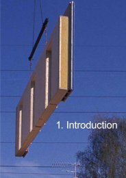
1. Introduction<br />
04.06.2010
Introduction <strong>TES</strong> EnergyFaçade<br />
01_16<br />
1.1.<br />
Modernisation - the 2nd Chance <strong>for</strong> Architecture<br />
<strong>TES</strong> EnergyFaçade is a <strong>system</strong>ised<br />
<strong>building</strong> method <strong>for</strong> the assembly of offsite<br />
fabricated customised <strong>timber</strong> façade<br />
panels, replacing either certain layers<br />
of, or the existing <strong>building</strong> envelope in<br />
its entirety. The basis <strong>for</strong> the use of <strong>prefabricated</strong><br />
retrofit <strong>building</strong> elements is a<br />
<strong>system</strong>atic process of surveying, renovation<br />
planning, construction and maintenance<br />
of the <strong>building</strong> stock.<br />
Modern methods <strong>for</strong> measuring (i.e.<br />
Photogrammetry and 3D laser scanning)<br />
generate precise data of the target <strong>building</strong>s<br />
<strong>for</strong> 3D-models, which are used <strong>for</strong><br />
designing <strong>prefabricated</strong> components <strong>for</strong><br />
renovating, and finally, <strong>for</strong> maintenance.<br />
The dataflow matches the requirements<br />
2. <strong>TES</strong> EnergyFaçade <strong>building</strong> method.<br />
of the digital process chain, from site measuring, planning to prefabrication.<br />
<strong>TES</strong> elements combine a self-supporting structure with insulation infill and panelling,<br />
which can be made of a wide range of cladding materials (e.g. <strong>timber</strong> boards,<br />
<strong>timber</strong> panels, glass, aluminium etc.). High precision <strong>building</strong> components like<br />
windows are easy to integrate due to the modularity.<br />
Retrofitting with customised <strong>TES</strong> elements can include:<br />
• Energy efficient retrofitting of façades and roof<br />
• Renewal or improvement of windows, modification of window openings,<br />
• Extensions, annexes or the addition of spatial elements or balconies<br />
• HVAC modernisation<br />
• Integration of solar-active components and / or passive solar heating <strong>system</strong>s<br />
Central characteristics of the <strong>TES</strong> method<br />
Construction<br />
• Self supporting <strong>timber</strong> frame structure<br />
• Precision and quality of a customised<br />
<strong>prefabricated</strong> <strong>building</strong> <strong>system</strong><br />
• Application of a large variety of cladding<br />
materials<br />
• Spatial intervention or modular expansion<br />
in a coherent <strong>system</strong><br />
• Integration of HVAC and solar-active<br />
components<br />
• Integration of load bearing elements<br />
1.<br />
Modernisation workflow
Introduction <strong>TES</strong> EnergyFaçade<br />
01_17<br />
Values<br />
Knowledge<br />
1. Characteristics of <strong>TES</strong> method<br />
• Architectural renewal<br />
• Modification of façade materials and<br />
openings<br />
• Improvement to the <strong>building</strong>s energy<br />
efficiency and increased living com<strong>for</strong>t<br />
• Ecology - use of <strong>timber</strong> <strong>based</strong> materials<br />
in façade elements<br />
• On-site productivity<br />
• Reduced construction time on-site =<br />
less noise and disturbance<br />
• Maintenance oriented and end-of-life<br />
design utilising LCA methods<br />
• Higher return on investment (ROI)<br />
through quality, holistic solutions and<br />
industrial productivity<br />
• Product endorsing an ecological lifestyle<br />
of health and sustainability<br />
(LoHaS)<br />
• Systemised workflow<br />
• Digital survey using reverse engineering<br />
methods from project start<br />
• Holistic planning process supported by<br />
BIM in design, realisation and maintenance<br />
Task and potentials<br />
Doubtless, the main task in Europe's construction activities in the future will be the<br />
renovation of the existing real estate stock with a strong focus on the ecological<br />
improvement of an energy efficient <strong>building</strong> envelope. The restriction of our energy<br />
resources will focus this need drastically. The urge to face up to the consequences<br />
of the climate change with the reduction of green house gases (GHG) has been<br />
underlined by the publication of the latest assessment report by the IPCC 1 in 2007.<br />
Buildings are responsible <strong>for</strong> 40% of energy consumption and 36% of EU CO2<br />
emissions. 2 Energy efficient <strong>building</strong> modernisation contributes to the reduction of<br />
GHG emissions to a significant extent.<br />
3. Global warming map, © by<br />
NASA.<br />
Resource efficiency is seen as another key factor in energy efficiency, since the<br />
construction sector is responsible <strong>for</strong> 40 % of EU material flows, as stated by the<br />
EU in the Sustainable Consumption and Production and Sustainable Industrial<br />
Policy Action Plan. 3<br />
Two strategies lead to possible solutions. The first relies on the safeguarding and<br />
reuse of existing <strong>building</strong>s and structures. A second approach promotes a stronger<br />
use of renewable resources like <strong>timber</strong>, <strong>timber</strong> products and other biogenic <strong>building</strong><br />
products in construction.<br />
1 IPCC, Forth Assessment Report, 2007<br />
2 http://ec.europa.eu/energy/efficiency/<strong>building</strong>s/<strong>building</strong>s_en.htm, verified 28.05.2010<br />
3 COM(2008) 397 final, Communication from the Commission to the European Parliament, The<br />
Council, The European Economic and Social Committee and the Committee of the Regions on the<br />
Sustainable Consumption and Production and Sustainable Industrial Policy Action Plan, http://eur-lex.<br />
europa.eu/LexUriServ/LexUriServ.douri=CELEX:52008DC0397:EN:NOT, verified 06.11.2009.
Introduction <strong>TES</strong> EnergyFaçade<br />
01_18<br />
<strong>TES</strong> EnergyFaçade concentrates on the development of a customised <strong>building</strong><br />
<strong>system</strong> using <strong>prefabricated</strong> <strong>timber</strong> framed elements including the integration of<br />
biogenic insulation materials and techniques, multiple glazing and HVAC components.<br />
“Realising these savings requires an integrated design process involving<br />
architects, engineers, contractors and clients, with full consideration of opportunities<br />
<strong>for</strong> passively reducing <strong>building</strong> energy demands. Over the whole <strong>building</strong> stock<br />
the largest portion of carbon savings by 2030 is in retrofitting existing <strong>building</strong>s<br />
and replacing energy-using equipment due to the slow turnover of the stock (high<br />
agreement, much evidence). 4 ”<br />
Building modernisation as a holistic intervention offers a 2nd chance <strong>for</strong> architecture<br />
and urban renewal, including infill development. A great number of <strong>building</strong>s<br />
in Europe built between 1950-1980 will in any case to be renovated within the next<br />
decade due to natural deterioration, technical, architectural and/or social aspects.<br />
With regards to this, the improvement of the envelope will offer major benefits to<br />
the <strong>building</strong>'s energy consumption saving potential and a vital contribution to the<br />
reduction of the global CO2 Stock. 5<br />
European wide, there is a particularly high backlog of energy efficient renovations<br />
to the insulation layer of the <strong>building</strong> envelopes, i.e. the exterior wall and roof structures.<br />
The wide spread and most common method is the improvement of the exterior<br />
wall through the application of external composite thermal insulation <strong>system</strong>s<br />
<strong>based</strong> mainly on mineral fibre or polystyrene foam - at the expense of a high outlay<br />
of primary energy <strong>for</strong> production. Their application is weather dependent (temperature<br />
above 5°C and dry conditions) and mounting becomes difficult with increasing<br />
thickness of the insulation layer.<br />
The common renovation practice can be characterised as follows: craftsmanlike,<br />
non-ergonomic procedures, use of pollutive insulation and construction materials,<br />
tailoring and processing on site with high dust and noise emission, substantial off<br />
cuts and pollution, disturbance to the neighbourhood. The use of <strong>prefabricated</strong><br />
<strong>system</strong>s and sustainable raw materials are minor exceptions to the rule.<br />
The exploitation of features of modern digital <strong>based</strong> survey of <strong>building</strong>s, transfer<br />
to CAD drawings and the prefabrication of large scale insulated elements is not a<br />
common practice.<br />
A <strong>TES</strong> retrofit is approached as a holistic <strong>building</strong> modernisation including the<br />
improvement of a <strong>building</strong>'s self sufficiency in energy production. This approach<br />
includes a dramatic reduction of heat and primary energy demand as well as the<br />
design and addition of energy productive elements, depending on local conditions.<br />
Measures to reduce the heat and primary energy demand in combination with the<br />
<strong>building</strong> envelope include:<br />
•<br />
•<br />
•<br />
•<br />
•<br />
•<br />
Minimisation of thermal transmission losses<br />
Airtightness Construction<br />
Ventilation with a high heat recovery ratio<br />
Windows with low U values<br />
Integration of shading devices<br />
Integration of solar active components<br />
The optimisation of the <strong>building</strong> envelope includes improving the insulation <strong>for</strong><br />
4 http://www.ipcc.ch/publications_and_data/ar4/wg3/en/ch6s6-es.html, verified 10.08.10, 14:00<br />
5 Schulze-Darup B. (2004) Energetische Gebäudesanierung mit Faktor 10, Deutsche Bundesstiftung<br />
Umwelt, Osnabrück.
Introduction <strong>TES</strong> EnergyFaçade<br />
01_19<br />
winter and summer, daylight use and the integration of technical features (HVAC,<br />
solar panels). A core task of energy efficient <strong>building</strong> design is to reach the required<br />
indoor environmental quality with a minimum of primary energy demand and<br />
a simple energy supply <strong>system</strong>. 6<br />
Improvement of Energy Efficiency / Energy efficiency as an architectural<br />
aspect<br />
Town planning measures have been developed to increase the density of existing<br />
urban structures which can be achieved by adding roof floors, neighbourhood<br />
specific infill developments or extension of <strong>building</strong> spaces. In addition, the <strong>TES</strong><br />
method <strong>for</strong> improving the energy efficiency of the <strong>building</strong> envelope completes the<br />
scope of ‘Additions & Alterations’ . Modern <strong>timber</strong> construction offers a consistent<br />
compatible <strong>building</strong> <strong>system</strong> and a wide range of spatial and technical solutions,<br />
which can be applied to the different tasks. The architectural appearance of both<br />
<strong>building</strong>s and built environment can be substantially improved by restructuring<br />
façades, exchanging façade materials, adding extensions, annexes or additional<br />
storeys. The geometry of the <strong>building</strong> may be modified by adjusting openings and<br />
integrating loggias or balconies to the heated living area. Aside from that, the existing<br />
built environment contains a cultural heritage which should be preserved <strong>for</strong><br />
future generations. A retrofit method which can be affixed to the existing substance<br />
and that is possible to dismantle thanks to its modular concept offers new perspectives<br />
<strong>for</strong> cultural preservation. Annexes or extensions can be added to the <strong>building</strong><br />
increasing the productive floor area.<br />
Infill development with <strong>TES</strong>:<br />
1.<br />
2.<br />
3.<br />
4.<br />
Additional storey<br />
Horizontal annex<br />
Infill of <strong>building</strong> volumes<br />
Replacement of / addition to <strong>building</strong> envelope<br />
4.<br />
Possible interventions<br />
Updating the <strong>building</strong> stock often require retrofitting strategies that not only improve<br />
the technical per<strong>for</strong>mance of a <strong>building</strong> but also adjust space and appearance<br />
and thus the architecture. These include the integration of technical <strong>system</strong>s,<br />
solar design and extensions or changes to the existing floor plan structure.<br />
Use, function, technical services and appearance of the <strong>building</strong> stock often no<br />
longer meet today's demands and expectations of modern architecture. Social and<br />
cultural ways of living and housing have changed - brought about by developments<br />
in family structures, work-life balance and aging societies etc. - and demanded<br />
adapted solutions. The appearance and functional properties of the <strong>building</strong> stock<br />
6 Hegger, Fuchs, Stark, Zeumer (2007) Energie Atlas, Institut für internationale Architektur-Dokumentation,<br />
München.
Introduction <strong>TES</strong> EnergyFaçade<br />
01_20<br />
are the results of the visions and inventions of their time and their renewal needs<br />
comprise aspects. In many cases the <strong>building</strong> structure can be modified and<br />
extended and retrofitting becomes a smart alternative to total demolition and<br />
re<strong>building</strong>. Schwanenstadt's school and the student apartments Neue Burse<br />
Wuppertal provide compelling examples. 7<br />
Particular interests<br />
Owners demand convincing figures <strong>for</strong> marketing and calculating returns on the<br />
investment of the measure whereas tenants benefit from increased com<strong>for</strong>t and<br />
reduced heating energy costs.<br />
The <strong>TES</strong> method <strong>based</strong> on the application of <strong>prefabricated</strong> customised large sized<br />
<strong>timber</strong> framed wall elements is a one-stop solution satisfying all modernisation requirements.<br />
Quality is ensured by the experience of the <strong>timber</strong> construction sector,<br />
providing a reliable <strong>system</strong> of <strong>timber</strong> framing technology and sustainable <strong>building</strong><br />
materials.<br />
The challenge of the task is not only the preservation of the existing <strong>building</strong> stock,<br />
cultural and architectural values but its metamorphosis as a response to future<br />
needs. Modifications offer the opportunity to add future oriented concepts and enduring<br />
cultural creation. Functional and constructive aspects can be remedied and<br />
the appearance modernised.<br />
5. Schwanenstadt, Austria<br />
School be<strong>for</strong>e and after modernisation;<br />
PAUAT Architekten, 2004<br />
The improvement of the <strong>building</strong> envelope will be a major benefit to the structure's<br />
energy saving potential and a vital contribution to household reductions of total<br />
CO2 emissions. In this context, <strong>timber</strong> <strong>building</strong> <strong>system</strong>s and biogenous <strong>building</strong><br />
materials can be considered to have outstanding qualities due to their ecological<br />
properties 8 .<br />
1.2.<br />
<strong>TES</strong> Method - Systemised Workflow<br />
The <strong>TES</strong> method is a <strong>system</strong>ised modernisation process from survey, planning,<br />
production off-site to assembly on-site as a consistent structure along a digital<br />
<strong>based</strong> workflow. It provides the essential data and allows the integration from first<br />
sketch to the mounted façade. Planning, energy simulation and production design,<br />
<strong>based</strong> on BIM data, supports the control of the energetic per<strong>for</strong>mance and<br />
economic optimisation. Furthermore the holistic method allows the integration of<br />
multiple functions in one <strong>building</strong> <strong>system</strong>, due to the openness of <strong>TES</strong> method, one<br />
of its core concepts. Necessary responsibilities of all participants are set within the<br />
frictionless digital workflow as state of the art in survey, planning and production.<br />
digital measurement – planning off-site fabrication – on-site assembly<br />
Prefabrication demands detailed in<strong>for</strong>mation on the renovation object. On the<br />
basis of an accurately measured <strong>building</strong> survey, customised <strong>TES</strong> elements are<br />
fabricated off-site according to the project specific design at the factory. These can<br />
include ready-assembled cladding, integrated window modules and, if necessary,<br />
interior surfaces.<br />
A shorter assembly process on-site and fewer restrictions due to construction work<br />
compared to conventional renovation methods is an exceptionally valuable quality<br />
<strong>for</strong> owner-occupied flats or <strong>building</strong>s under operation.<br />
6. Risør College, Norway<br />
Prefabricated façade elements with<br />
close boarding, assembled in 2009.<br />
7 Schule Schwanenstadt, Austria; PAUAT Architekten; 2004; Neue Burse, Germany; Architektur<br />
Contor Müller Schlüter, 2000-2003.<br />
8 Wegener et al. (2010) Bauen mit Holz = aktiver Klimaschutz, TUM Holz<strong>for</strong>schung München,<br />
München.
Introduction <strong>TES</strong> EnergyFaçade<br />
01_21<br />
Characteristics of the <strong>TES</strong> method<br />
Heating energy demand and green house gas emissions can effectively be reduced<br />
by thermal enhancement of the <strong>building</strong> envelope, i.e. improvement of<br />
airtightness and the reduction of heat transmission through the <strong>building</strong> skin. Outer<br />
walls count <strong>for</strong> up to 80 - 90% of assembly related heat energy saving potential,<br />
windows <strong>for</strong> around 50%. 9<br />
roof:<br />
up to 85%<br />
window:<br />
up to 56%<br />
façade:<br />
up to 86%<br />
basement:<br />
up to 65%<br />
<strong>building</strong> services:<br />
up to 25%<br />
7.<br />
Reduction potential of heat loss in modernised <strong>building</strong>s.<br />
Source: IWU “Gebäudetypologie Bayern”, Eberhard Hinz, 27.02.2006.<br />
Retrofit interventions <strong>for</strong> energy efficiency.<br />
9 Institut Wohnen und Umwelt (IWU) (ed.) (2006): Gebäudetypologie Bayern, Darmstadt, p. 15ff.
Introduction <strong>TES</strong> EnergyFaçade<br />
01_22<br />
Prefabrication<br />
In the <strong>timber</strong> construction sector, advanced methods of prefabrication 10 are very<br />
successfully used in a contemporary fashion to produce and sell new energy efficient<br />
<strong>building</strong>s, and are consistently gaining market share. Prefabrication allows<br />
the integration of <strong>building</strong> components such as windows, <strong>building</strong> services <strong>system</strong>s<br />
and ready-made surfaces of the façade elements in the controlled and ergonomic<br />
working environment of the factory. A flexible workflow from design to production<br />
allows <strong>for</strong> customised fabrication of single <strong>building</strong> parts, taking into account the<br />
specific needs of individual <strong>building</strong>s, e.g. size, unevenness etc.<br />
Digital Surveying - Reverse Engineering<br />
8. Prefabricated façade element<br />
assembly at Realschule Buchloe.<br />
Combining the conditions of an existing object with new adapted and industrially<br />
manufactured parts leads to the paradigm of reverse engineering (RE). RE is<br />
described as the concept of planning and production of parts <strong>based</strong> on a digital<br />
model derived from digital imaging results which are taken from a physical object.<br />
Survey methods applied are photogrammetry, tachymetry and/or 3D laser scanning.<br />
Digital Workflow<br />
Planning methods are <strong>based</strong> on CAD/CAM models <strong>for</strong> production, integrating the<br />
results of RE. The high accuracy and the control over data integrity is backed-up<br />
by a digital workflow. Building in<strong>for</strong>mation modelling as a tool integrates all in<strong>for</strong>mation<br />
and supports the planning, construction and maintenance process. Lastly<br />
the digital workflow ensures the stencil like fit of the new <strong>TES</strong> elements onto the<br />
existing façade.<br />
On-site Productivity<br />
The builder will be able to achieve higher work productivity <strong>for</strong> the whole process<br />
and especially the mounting phase. Supply processes <strong>for</strong> elements can be optimised<br />
in the workshop, e.g. material flow and efficiency, machine employment,<br />
etc.. The work load on-site is minimised to the handling of just-in-time provided<br />
parts. This avoids organisational work, unproductive time, preparation work and<br />
enhances the productivity on-site substantially.<br />
Architectural Renewal<br />
The use, function, technical services and appearance of the <strong>building</strong> stock often<br />
no longer meet todays demands and expectations of modern architecture. Building<br />
modernisation becomes the 2nd chance <strong>for</strong> architecture, improving the technical<br />
per<strong>for</strong>mance of a <strong>building</strong>, adjusting space and appearance. <strong>TES</strong> EnergyFaçade<br />
includes the integration of technical <strong>system</strong>s, solar design and solutions <strong>for</strong> extensions<br />
or changes to the existing layout. The <strong>timber</strong> frame structure provides a<br />
certain load bearing capacity, allowing the application of different surface and<br />
cladding materials.<br />
10 Kolb, Josef (2007) Holzbau mit System, Birkhäuser, Basel.
Introduction <strong>TES</strong> EnergyFaçade<br />
01_23<br />
Ecology<br />
The target of the <strong>TES</strong> method is primarily focused on the <strong>building</strong>'s energy efficiency<br />
improvement and as a consequence in the reduction of GHG emissions. Every<br />
activity in construction is responsible <strong>for</strong> the consumption of additional resources<br />
in the <strong>for</strong>m of raw materials or energy and there<strong>for</strong>e cause emissions. A possible<br />
solution to this dilemma is the adoption of a sustainable and ecological retrofit<br />
method <strong>based</strong> preferably on biogenic materials.<br />
The theoretical model of a sustainable development path <strong>for</strong> the global society<br />
was offered by the Brundtland commission report “Our Common Future” and is<br />
<strong>based</strong> on the vision of a conscious style of consumption in order to preserve a high<br />
standard of living <strong>for</strong> future generations.<br />
The European Committee <strong>for</strong> Standardisation defined a first standard <strong>for</strong> sustainability<br />
in construction, the prEN 15643 11 . Providing a holistic view of the entire<br />
life of a construction “product”, it evaluates ecology, economy and society related<br />
qualities as equivalents, which have to be recovered.<br />
9.<br />
Simplified lifecycle model of a <strong>TES</strong> EnergyFacade retrofit.<br />
Life Cycle in Retrofit Projects<br />
A life cycle concept covers the optimisation of the overall per<strong>for</strong>mance of a <strong>building</strong><br />
from "cradle to grave". The per<strong>for</strong>mance is documented and evaluated according<br />
to the criteria of the standard prEN 15643 standards. The life cycle is separated<br />
into four phases in <strong>building</strong> life:<br />
•<br />
•<br />
•<br />
•<br />
Product phase (production of construction materials and assemblies)<br />
Construction phase (erection or retrofit of a <strong>building</strong>)<br />
Operation phase (use as long as the functional requirements are fulfilled)<br />
Disposal and recycling phase (partly or total demolition when technical<br />
requirements are no longer economically viable)<br />
There are approved concepts <strong>for</strong> excellent energy-efficient houses like the passive<br />
house as well as plus energy houses, as shown in the Solar Decathlon competition.<br />
The construction industry accounts <strong>for</strong> the highest material flows of all<br />
economic sectors in the EU. Every action in construction causes enormous waste<br />
streams. However the focus now has to be on the product phase, how to bring<br />
11 prEN 15643:2009: Sustainability of construction works. Assessment of <strong>building</strong>s.
Introduction <strong>TES</strong> EnergyFaçade<br />
01_24<br />
<strong>for</strong>ward the realisation of innovative concepts in the most effective and sustainable<br />
way. Durable, fully recyclable or reusable and safe products are needed <strong>for</strong> energy<br />
and resource efficient houses wether new <strong>building</strong> or retrofit.<br />
Timber Based Materials<br />
Against the background of essential climate change action, energy and resource<br />
efficient use of <strong>building</strong> materials plays a vital role. Timber and <strong>timber</strong> <strong>based</strong> <strong>building</strong><br />
materials gain added importance due to their positive primary energy demand<br />
from cradle to grave and carbon-footprints. 12 Advanced planning tools and construction<br />
methods, <strong>based</strong> on the thorough experience of the <strong>timber</strong> construction<br />
sector open the door to sophisticated <strong>timber</strong> construction <strong>system</strong>s <strong>for</strong> <strong>building</strong><br />
modernisation.<br />
Maintenance and End-of-Life Design<br />
<strong>TES</strong> EnergyFaçade is a retrofit <strong>system</strong> which prolongs an existing <strong>building</strong>'s life<br />
and improves its technical and functional properties. The conditioning of retrofit<br />
products has to be considered from a life cycle point of view, as one of the commandments<br />
of sustainability and as the input of new material or the disposal of<br />
waste <strong>building</strong> material is costly. Every retrofit solution has an end-of-life caused<br />
by normal deterioration and more efficient and alternative retrofit interventions.<br />
End-of-Life design concerns waste management and recycling solutions <strong>for</strong> endof-life<br />
of <strong>TES</strong> EnergyFaçade.<br />
During <strong>building</strong> operation – the longest phase in a <strong>building</strong>'s life – the main interest<br />
is life cycle costing. The cumulation of all costs over the structure's operational life,<br />
<strong>for</strong> regular cleaning, repair and running a facility, can by far exceed the investment.<br />
Experience from research projects reflect the high level of life cycle costs. Maintenance<br />
and repair are big issues <strong>for</strong> climate exposed <strong>building</strong> envelopes. There<strong>for</strong>e<br />
an individually planned solution helps to avoid the risks of high operational costs.<br />
An apparently cheap solution can lead to high life cycle costs exceeding those of<br />
the investment. On the other hand, a higher investment in an upgrade solution will<br />
in most cases create lower life cycle costs.<br />
Sustainable Economy (Return on Investment)<br />
The basic concept of sustainable economy is the limit of natural resources. Improved<br />
<strong>building</strong> envelopes are a basic condition <strong>for</strong> the substantial reduction of<br />
the energy demand in housing. Consequently the insulation methods of <strong>building</strong>s<br />
have to be considered carefully in respect of resource saving. Currently available<br />
methods are largely <strong>based</strong> on non-renewable resources as well as consuming a<br />
large amount of energy and causing air pollution during production and disposal. A<br />
less resource-consuming substitute is needed which is both more ecological and<br />
provides other positive aspects of sustainability. The <strong>TES</strong> EnergyFaçade method<br />
provides these future oriented features as well as providing added value. <strong>TES</strong> materials<br />
are <strong>based</strong> on renewable resources mainly from <strong>timber</strong> and the installation<br />
method minimises the disturbance of inhabitants during construction work.<br />
Sustainable economy requires lifecycle observation and a long-term preservation<br />
of resources instead of an optimal consumption of them. There<strong>for</strong>e economic<br />
calculations have to take the entire <strong>building</strong> life into consideration.<br />
12 Wegener et al. (2010)
Introduction <strong>TES</strong> EnergyFaçade<br />
01_25<br />
In lifecycle observation the minimisation of life cycle costs <strong>for</strong> the operation of<br />
the <strong>building</strong> are essential. They are kept low by the good thermal insulation of the<br />
<strong>building</strong> envelope. Another important issue is the durability of facade <strong>system</strong> providing<br />
shelter, functionality and thermal insulation of the envelope.<br />
From an economic point of view the conservation of existing asset give positive<br />
values, because the resources stored in the asset are kept and reused. The future<br />
development of the value of the asset should be secured due to its sustainable<br />
profile and low operation costs.<br />
Quality<br />
A quality retrofitted project is a conservation of values or an added value. A satisfactory<br />
result can only be achieved if a QA <strong>system</strong> covers the entire life-span -<br />
from the process of retrofitting to the management and maintenance of the operational<br />
phase of the <strong>building</strong>. The overall objective is to ascertain that all predefined<br />
requirements will be reached and that the <strong>building</strong> as a <strong>system</strong> of envelope and<br />
interior conditioned space will solve the needs of its users and the expectations of<br />
the client.<br />
Contractors (e.g. carpenters) would not be able to achieve a high quality standard if<br />
they were the only ones responsible <strong>for</strong> the <strong>building</strong> process. Planning and project<br />
organisation have a significant effect on the outcome. There<strong>for</strong>e all participants in<br />
the <strong>building</strong> process have to be involved in quality assurance measures through<br />
out all phases. Quality standards are well-established in the <strong>timber</strong> industry.<br />
10.<br />
Wide variety of surface solutions <strong>for</strong> <strong>TES</strong>.<br />
Oberflächen<br />
Lifestyle Product - Business Model<br />
Private customers today are more interested in ecology, health and sustainability<br />
of industrial products than in earlier times. Firms are also more conscious of corporate<br />
social responsibility and may there<strong>for</strong>e include real estate in their strategic<br />
decision-making by investing in environmentally-labelled <strong>building</strong>s. As a result a<br />
range of less polluting and energy saving techniques, using renewable resources,<br />
can be identified. The holistic concept of <strong>TES</strong> aims at least at a balance of these<br />
customer interests. Hence they combine a modern and high quality retrofitting<br />
method and an innovative product with sound ecological, economic and social or<br />
cultural values.
Introduction <strong>TES</strong> EnergyFaçade<br />
01_26<br />
Pro-active entrepreneurs in the <strong>timber</strong> sector have the chance to adopt the process<br />
and extend their portfolio with sustainable renovation products. Possible models<br />
are the original equipment manufacture (OEM) with production lines <strong>for</strong> raw<br />
façade elements. Another model may be the integrator using OEM products and<br />
integrating additional features. Further there are traditional reseller or assembler<br />
business models.<br />
Of course it is also possible to invent additional business models providing service<br />
agreements <strong>for</strong> maintenance, repair, warranty and recycling businesses. For example<br />
costly disposal solutions can be separated out by a taking back or recycling<br />
guarantee from the carpenter.<br />
Finally a futuristic vision may be the combination of energy contracting, emissions<br />
trading or emissions credit and compensation <strong>system</strong> integrated in holistic retrofit<br />
solutions.
Introduction<br />
Building Stock <strong>TES</strong> EnergyFaçade Facade<br />
03_27 A_27<br />
2. Building Stock<br />
04.06.2010
Building Stock <strong>TES</strong> EnergyFaçade<br />
03_28<br />
2.<br />
Building Stock<br />
Throughout Europe there is no comprehensive data regarding exact figures of<br />
<strong>building</strong> typology, number, age and status.<br />
Building Age Classes<br />
are an instrument of statistical classification<br />
of the <strong>building</strong> stock. They<br />
cluster existing <strong>building</strong>s according<br />
to their distinct <strong>building</strong> methods<br />
and construction types into coherent<br />
time sections. The time span <strong>for</strong><br />
a class is defined with reference to<br />
technological changes in <strong>building</strong><br />
and construction sector, new regulations<br />
(e.g. energy saving regulations)<br />
or historical breaks (war).<br />
In order to evaluate the demand and potential of necessary <strong>building</strong> modernisation,<br />
our approach is <strong>based</strong> on available national and regional data resources from research<br />
reports on the <strong>building</strong> stock. Whereas in Finland and Norway these figures<br />
are rather incomplete, in Germany most comprehensive data is provided by the<br />
Institut Wohnen und Umwelt (IWU), Darmstadt, Germany. Their data is especially<br />
generated <strong>for</strong> the purpose of evaluating the energy saving potential of the <strong>building</strong><br />
stock. The number of the type of <strong>building</strong>s in the relevant <strong>building</strong> age classes<br />
and their actual condition is the most essential characteristic of this data. It clearly<br />
shows the economic potential according to energy savings and the available<br />
façade area <strong>for</strong> renovation. The following details are considered as an essential<br />
summary <strong>for</strong> the target group of <strong>building</strong>s preferred <strong>for</strong> the <strong>TES</strong> method.<br />
Building Age Classes<br />
A statistical classification <strong>for</strong> the <strong>building</strong> stock in Germany is clustering <strong>building</strong>s<br />
in age classes, grouping existing <strong>building</strong>s due to their distinct <strong>building</strong> methods<br />
and construction types. The time span <strong>for</strong> a class is defined according to changes<br />
in <strong>building</strong> and construction (<strong>building</strong> industry), new regulations (e.g. heating energy<br />
demand) or historical breaks (war). Data is provided on the number of different<br />
<strong>building</strong> types per class, condition, energetic standard, <strong>building</strong> method as well<br />
as preferred construction materials.<br />
The following figures 1 show the range of residential <strong>building</strong>s specified by age and<br />
quantity. Buildings of the time span from the 1950s to the early 1980s constitute<br />
nearly 50 % of the German <strong>building</strong> stock and account <strong>for</strong> around 8.5 million units.<br />
This amount illustrates the reduction potential of energy demand, as these <strong>building</strong>s<br />
consume between 150 and 250 kWh/m²a in their unrefurbished status. As<br />
the urge <strong>for</strong> comprehensive retrofitting of the entire <strong>building</strong> stock is evident and<br />
generally recognised, we have not concentrated in further specification of diverse<br />
stock figures.<br />
1 Destatis (2006), Mikrozensus-Zusatzerhebung 2006 - Bestand und Struktur der Wohneinheiten -<br />
Fachserie 5 Heft 1
Building Stock <strong>TES</strong> EnergyFaçade<br />
03_29<br />
11.<br />
Residential units by <strong>building</strong> age class, Germany.<br />
Three <strong>building</strong> age classes between 1950 and 1980 exemplify the development<br />
and major changes in urbanism, typology and construction which are defined in<br />
the German context.<br />
1950s<br />
Urbanism<br />
Typology<br />
Construction<br />
Deficiencies<br />
Weakness<br />
1960s<br />
Urbanism<br />
Typology<br />
Construction<br />
Shortages<br />
Developments with low density, open and green spaces<br />
nearby or inside the city centre.<br />
Multi-storey dwellings up to 5 or 6 levels with interior staircase<br />
and seldom with arcade.<br />
Load bearing masonry walls with punctuated façades<br />
and concrete floor slabs. Façades are designed calm and<br />
smooth, balconies are rare.<br />
Preferred <strong>building</strong> material after the war: reused bricks,<br />
poor quality concrete and plaster with insufficient aggregate.<br />
Windows, wood framed without sealing and doubleglazed<br />
casements, most of which have been replaced since<br />
the 1980s with PVC framed, insulated glass windows.<br />
No insulation of the envelope, floor slabs tailed in thin<br />
outer walls, window joints in offset reveals, low U-value of<br />
window construction, poor roof construction without any<br />
insulation.<br />
Densified large development areas, closed spaces, located<br />
in outskirts.<br />
Medium to large scale housing complexes, apartments with<br />
large floor space.<br />
Simple compound or monolithic structures, intensified use<br />
of concrete, large façade openings, structured façades and<br />
additional loggias and balconies. Availability of industrial<br />
façade <strong>system</strong>s, <strong>timber</strong> and metal window frames with<br />
single glazing.<br />
Poor <strong>building</strong> and construction standards, low quality construction.
Building Stock <strong>TES</strong> EnergyFaçade<br />
03_30<br />
Weakness<br />
1970<br />
Urbanism<br />
Typology<br />
Construction<br />
Deficiencies<br />
Weakness<br />
Façade openings and construction, missing insulation layer.<br />
High density, large development areas with green spaces.<br />
High-rise <strong>building</strong>s, large-scale housing complexes, smaller<br />
floor area.<br />
Intensively <strong>prefabricated</strong>, structuraly optimised, high quality<br />
concrete structures, concrete skeleton frames. Layered<br />
and structured façades, façade cladding and curtain wall<br />
façades with material mix or sandwich construction, single<br />
layer glazing.<br />
Poor <strong>building</strong> standards and construction related to <strong>building</strong><br />
physics, leaking joints, technical defects of façades,<br />
problems of mass production and material quality, economy<br />
of materials.<br />
Missing or minimized insulation, massive thermal bridges<br />
by cantilevering <strong>building</strong> parts in façades, poor energetic<br />
quality of façades and windows.<br />
Building Type and Size<br />
A successful economical retrofit with <strong>TES</strong> elements is suitable <strong>for</strong> <strong>building</strong>s of a<br />
particular size and volume as well as a rational façade layout. Suitable <strong>building</strong><br />
types may be office <strong>building</strong>s, public <strong>building</strong>s (schools etc.) or apartment <strong>building</strong>s<br />
(multiple dwelling). The area of the <strong>building</strong> envelope as well as a regular and<br />
almost repetitive façade design are decisive advantages.<br />
12. Typical appartment houses of<br />
the post war era.
Building Stock <strong>TES</strong> EnergyFaçade<br />
03_31<br />
Relevant types of houses in multistorey dwellings:<br />
• Divided dwelling types (double, triple, quadruple dwellings) with a decentralised<br />
staircase in front of or close to the outer wall (typical in row houses<br />
or in downtown slab block structures).<br />
• Point blocks with central staircases mostly inside the core of the <strong>building</strong><br />
with 4-8 residential units per level (solitary <strong>building</strong>s in urban fabric).<br />
• Special types with a central staircase are staggered plans with triple or<br />
quadruple dwellings in order to enlarge daylight input. (solitary or terraced<br />
house).<br />
• Outdoor corridor types with decentralized staircases and floor wise, external<br />
horizontal access corridor (terraced houses, seldom solitary).<br />
• Terraced- /stepped houses with central or decentralised staircase and<br />
optional horizontal access corridor (solitary).<br />
01_02 terraced houses 01_03 row house 01_04 point house 01_05 stepped house<br />
02_01 shear wall 02_02 skeleton 02_03 crosswall 02_04 crosswall-ribbon window<br />
03_01 exterior access partly demolition of exterior access<br />
support and new facade layer<br />
new built exterior access in front of<br />
new facade layer<br />
new facade layer enclosures the<br />
exterior access<br />
13.<br />
03_02 existing situation cantilevering<br />
balcony, balcony demolition<br />
Typology of relevant <strong>building</strong> types.<br />
balcony enclosure<br />
balcony enclosure and<br />
new facade layer<br />
new facade layer and addition of<br />
new balcony
Building Stock <strong>TES</strong> EnergyFaçade<br />
03_32<br />
14. Typological floor plans with<br />
corridor houses and terraced<br />
houses (from left t. r.): acc. to Neufert,<br />
1973.<br />
15. Typological floor plans with<br />
centralised access (from left t. r.):<br />
double dwelling, triple dwelling,<br />
staggered dwelling, Point block,<br />
acc. t. Neufert, 1973.<br />
•<br />
.<br />
16. Examples of German dwellings<br />
from the 60s and 70s in<br />
Nuremberg.
Building Stock <strong>TES</strong> EnergyFaçade<br />
03_33<br />
2.1.<br />
Energy Efficiency in Building Stock<br />
The <strong>building</strong> stock in the EU accounts <strong>for</strong> up to 40% of the final energy demand<br />
used <strong>for</strong> heating our houses. Reduction of this energy demand is the most complex<br />
and challenging, but also the most promising contribution to the climate saving<br />
ef<strong>for</strong>ts. There is a high potential to reduce the energy demand of <strong>building</strong>s from the<br />
1950’s to the early 1980’s. Since the 1980s the first energy efficiency regulations<br />
came into effect.<br />
17.<br />
Building stock clustered in <strong>building</strong> age classes and its specific heat energy demand.<br />
The main reasons <strong>for</strong> the high energy demand are poor constructions with high<br />
rates of transmission heat loss, ventilation heat loss and inefficient <strong>building</strong><br />
services <strong>system</strong>s. The causes are the very poor construction standards of the post<br />
war era, followed by a deficient insulation quality of mass produced large-scale<br />
dwellings in social housing programmes in the late 60s and in the 70s. These<br />
industrialised fabricated <strong>building</strong>s - found all over Europe - face the problem of<br />
often thin, permeable walls, bad window solutions and problematic construction<br />
joints and almost no heat insulation. This results in an immense heating energy<br />
demand in the range of 150 – 250 kilowatt-hours per square meter and year (kWh/<br />
m 2 a) compared to 50 kWh/m 2 a prescribed <strong>for</strong> a low-energy <strong>building</strong>. 2<br />
1. WSchVO 1977,<br />
k-values<br />
[W/m 2 K]<br />
EnEV 2009,<br />
U-values<br />
[W/m 2 K]<br />
“Passivhaus”<br />
new <strong>building</strong><br />
Windows 3,0 1,3 (1,1) 0,8 (0,65)<br />
(glazing)<br />
Walls 0,78 (A/V > 1,2) 0,24 ≤ 0,15<br />
-1,4 (A/V < 0,24)<br />
Roof (flat) < 0,45 0,24 (0,2) 0,12 (0,1)<br />
Basement < 0,8 0,3 ≤ 0,15<br />
floor<br />
2. Table: German thermal protection regulations compared to „Passivhaus“ rules.<br />
2 EnEV 2009 was introduced on 1.10.2009. Main cornerstones include a 30 % reduced heating<br />
energy demand compared to EnEV 2007 and 30 % lower U-values
Building Stock <strong>TES</strong> EnergyFaçade<br />
03_34<br />
A <strong>for</strong>ceful reduction of the heating energy demand and the improvement of living<br />
com<strong>for</strong>t affects the <strong>building</strong> services technology. Smaller, more efficient heating<br />
devices or even a change of the entire heating <strong>system</strong> <strong>for</strong> a dwelling will be necessary.<br />
Heating <strong>system</strong>s <strong>for</strong> multi-storey <strong>building</strong>s of the 50s - 70s generate too<br />
much energy, they are inefficient and technically out-of-date.<br />
18.<br />
Type of heating <strong>system</strong> in residential units in millions.<br />
Changing an energy supply <strong>system</strong> (heating, ventilation) is a major intervention into<br />
the spacial structure of a <strong>building</strong>. It necessitates a lot of construction work inside<br />
the apartments causing disturbance stress <strong>for</strong> people living or working there.<br />
Thus, intelligent solutions <strong>for</strong> innovative heating technology in all fields, capturing,<br />
storage and distribution are on demand. With innovation in façade renovation the<br />
new envelope products can provide a plat<strong>for</strong>m <strong>for</strong> integrating the distribution into<br />
the new façade layer e.g. with routing outside the flat minimising interventions on<br />
the inside.<br />
Indeed meeting today’s legal standards <strong>for</strong> a retrofitted <strong>building</strong> requires little architectural,<br />
technical, economical and energetic ef<strong>for</strong>t. A more challenging objective<br />
is a factor 10 reduction - which stands <strong>for</strong> the paradigm of the Passive-House. 3<br />
After the Passivhaus was well and thoroughly tested in new <strong>building</strong> there have<br />
been several examples of renovations of existing <strong>building</strong>s over the last 8 years. 4<br />
Reaching the standards of a Passive-house and its main objective, a minimised<br />
heat energy demand of 15 kWh/m 2 a heat energy demand, needs a set of actions<br />
attuned to the individual situation. Limiting design parameters like the orientation<br />
or the A/V ratio are pretended in a close range. Reaching the objectives is only<br />
possible by considering the full sum of interventions. Every one of them, from heat<br />
transmission to Passive-house suited <strong>building</strong> services <strong>system</strong>s, has to be optimised<br />
closely in relation to each other.<br />
3 Passivhaus Institut, http://www.passiv.de, verified 06.11.2009.<br />
4 Schulze-Darup (ed.) (2008) Energetische Gebäudesanierung mit Faktor 10, Deutsche Bundesstiftung<br />
Umwelt (DBU) research report series, Osnabrück.
Building Stock <strong>TES</strong> EnergyFaçade<br />
03_35<br />
2.2.<br />
Resource Efficiency in Building Stock<br />
A renovation project concerns enormous flows of material from the recycling of<br />
existing construction material to the new material needed <strong>for</strong> renovation with consequences<br />
<strong>for</strong> economically motivated decisions during the renovation process.<br />
There is a need to consider all <strong>for</strong>ms of energy in the built-environment whether<br />
in the erection phase or during the operational phase. The latter normally greatly<br />
exceeds the energy demand of the <strong>for</strong>mer. This aspect has to be considered carefully,<br />
because the relationship of the embodied energy and the energy used <strong>for</strong><br />
heating is changed with a high rate. In addition the amount of embodied energy<br />
incorporated in construction material is relatively high, especially in oil- or mineral<strong>based</strong><br />
materials, compared to such as from renewable resources. Construction<br />
material with a high energy potential dominates the market.<br />
Accordingly the refurbishment of usable material, generally the <strong>building</strong>’s structure,<br />
is a necessary step to prolong the life span of a <strong>building</strong> and save the energy<br />
embodied in the materials of existing <strong>building</strong>s. Other <strong>building</strong> parts, with an interface<br />
role, such as façades, are more difficult to preserve or have to be massively<br />
improved.<br />
Of course the most important contribution to life cycle impact categories come<br />
from reused structural <strong>building</strong> parts, which account <strong>for</strong> about one third (e.g. floors,<br />
walls) of the impact. 5 Eco balancing or life cycle analysis can identify vital aspects<br />
and assists decision on strategies <strong>for</strong> optimization the ecological impact of renovation<br />
projects.<br />
A common alternative to renovation is demolition. Arguments are often made,<br />
claiming higher cost efficiency or economic advantages <strong>for</strong> a new <strong>building</strong>. The<br />
opposite is in fact true as highlightend <strong>for</strong> example in school renovations in<br />
Schleswig–Holstein, Germany. 6 Moreover additional costs <strong>for</strong> new <strong>building</strong> are<br />
generated as side effects, such as temporary <strong>building</strong>s, rent <strong>for</strong> the substitution<br />
of spaces and higher operational costs during the construction phase. In addition<br />
there are considerable high fixed costs <strong>for</strong> demolition and disposal of the old <strong>building</strong>.<br />
To this end it can be concluded that the life cycle of a <strong>building</strong> is another influential<br />
lever to preserve resources <strong>for</strong> future generations. Compared to consumer products<br />
<strong>building</strong>s have very long operational phases and often host different usages<br />
over their whole product life.<br />
In summary:<br />
• Resource efficient modernisation and renovation of the <strong>building</strong> stock is<br />
recycling at lowest energetic levels and reduction of carbon dioxide emissions.<br />
• Costs <strong>for</strong> renovation are cheaper in most cases than demolition, especially<br />
when additional costs <strong>for</strong> new <strong>building</strong> on the same site raise the total<br />
budget.<br />
• Economic decisions need a thorough analysis of all data related to different<br />
renovation scenarios at an early stage, when conceptual influence has<br />
the highest impact on project costs.<br />
5 SIA D0200 (2004) SNARC, Systematik zur Beurteilung der Nachhaltigkeit von Architekturprojekten<br />
für den Bereich Umwelt, Zürich.<br />
6 Fechner O. (2009) Einsatz von Holzbauelementen zur energetischen Gebäudesanierung öffentlicher<br />
Nichtwohnungsbauten in: Proceedings Timber Construction NordBau 2009, Lübeck.
Building Stock <strong>TES</strong> EnergyFaçade<br />
03_36<br />
Balancing Resources<br />
A closer look at lifecycle shows another key issue when talking about existing<br />
<strong>building</strong>s. Around half of the <strong>building</strong> stock has reached half of its predicted lifetime<br />
or even less. The average lifecycle, <strong>for</strong> example of rendered masonry façades with<br />
structural requirements, is up to 120 years according to the guideline of the BBR. 7<br />
The proper conservation of these <strong>building</strong>s will be a major task. The result of retrofit<br />
there<strong>for</strong>e will be of much higher technical quality and will increase the value of<br />
the asset.<br />
Together with an energetic enhancement of the <strong>building</strong> skin a modernisation<br />
will cause higher costs compared to a simple colour renovation. One advantage<br />
in renovating existing <strong>building</strong> stock is the resource efficiency of reusing <strong>building</strong><br />
materials and whole <strong>building</strong>s. The material balance and the resulting energy balance<br />
<strong>for</strong> construction material will be raised by additional insulation material of the<br />
<strong>building</strong> envelope. The resource balance of a project after a sensitive retrofit can<br />
be more beneficial than that of a new build energy efficient <strong>building</strong>. The relation<br />
between the existing material stock and the additional <strong>TES</strong> layer are a topic of the<br />
<strong>for</strong>thcoming Smart<strong>TES</strong> research project. 8<br />
Building Skin and Energy Consumption<br />
The improvement of the <strong>building</strong> envelope is one of the most important parameters<br />
in the reduction of heat loss in a <strong>building</strong>. The improvement of airtightness and<br />
the reduction of heat transmission through the <strong>building</strong> skin is able to drastically<br />
reduce energy demand. The energy saving potential <strong>for</strong> <strong>building</strong>s of high energy<br />
consumption is up to 80 - 90% <strong>for</strong> the outer walls and around 50% <strong>for</strong> windows. 9<br />
Renovation of the façade with <strong>TES</strong> improves the <strong>building</strong> and prolongs its lifecycle.<br />
The new skin provides technical functionality and ensures shelter and weather<br />
protection <strong>for</strong> the structural parts of the <strong>building</strong>.<br />
The following <strong>system</strong>ised overview explains the main elements of the <strong>building</strong> envelope<br />
and compares the requirements within the retrofitting context.<br />
7 BBR (ed.) (2001) Leitfaden Nachhaltiges Bauen, Bonn. http://www.nachhaltigesbauen.de/fileadmin/pdf/PDF_Leitfaden_Nachhaltiges_Bauen/Leitfaden.pdf,<br />
verified 20.10.2010.<br />
8 Smart<strong>TES</strong>, Innovation in <strong>building</strong> construction <strong>for</strong> the <strong>building</strong> modernisation. Funded by Woodwidsom-Net<br />
2. Project duration 10/2010 – 10/2013.<br />
9 IWU (ed.) (2006): Gebäudetypologie Bayern, Darmstadt. p.15ff.
Building Stock <strong>TES</strong> EnergyFaçade<br />
03_37<br />
2.3.<br />
Systemisation<br />
Monolithic structure<br />
Skeleton<br />
19.<br />
Load bearing outer walls versus a skeleton structure with infill.<br />
Erstellt mit einer Schulversion von Nemetschek<br />
Load bearing<br />
structure<br />
Erstellt mit einer Schulversion von Nemetschek<br />
Load bearing <strong>building</strong><br />
envelope<br />
Columns, beams and<br />
slabs<br />
Survey<br />
Construction<br />
Intervention<br />
Mounting<br />
• Precise measurement<br />
of openings<br />
• Small tolerances <strong>for</strong><br />
large <strong>TES</strong> elements<br />
- higher ef<strong>for</strong>t<br />
Wall: monolithic - brick or<br />
concrete<br />
Ceiling; concrete or precast<br />
concrete<br />
Preservation of existing<br />
envelope. Change or<br />
enlargement of windows<br />
and doors in the exterior<br />
wall<br />
+ Modification of <strong>building</strong>s<br />
under operation<br />
possible<br />
Vertical load on foundation<br />
or anchor.<br />
Anchoring to ceiling front<br />
side (dowel)<br />
• Survey of ceiling edges<br />
and columns<br />
• Higher tolerances<br />
+ smaller ef<strong>for</strong>t<br />
Columns, ceillings and<br />
panels in one material<br />
only<br />
(concrete, steel or <strong>timber</strong>)<br />
or mixed structure<br />
Part or total demolition of<br />
<strong>building</strong> envelope.<br />
- Cost <strong>for</strong> disposal<br />
- Interference with<br />
<strong>building</strong> operation<br />
Vertical load on foundation<br />
or anchor.<br />
Storey wise position on<br />
ceiling edges.
Building Stock <strong>TES</strong> EnergyFaçade<br />
03_38<br />
Design and space<br />
Enlargement of openings<br />
by demolition of sill<br />
possible, to the side and<br />
height high ef<strong>for</strong>t<br />
Wide range of creative<br />
possibilities <strong>for</strong> façade<br />
design<br />
2.3.1.<br />
Building Geometry<br />
Systematic overview of standard geometrical situations as a basis <strong>for</strong> the application<br />
of <strong>TES</strong> elements.<br />
Roof<br />
• pitched<br />
• flat<br />
Ceiling / balcony<br />
• Balcony<br />
• Loggia<br />
• Access balcony<br />
Window / door<br />
Wall<br />
• Corner<br />
• Surface<br />
• Joints<br />
Outer corner<br />
Inner corner<br />
Foundation<br />
• Basement heated /<br />
not heated<br />
• Ground slab<br />
cantilevering
Building Stock <strong>TES</strong> EnergyFaçade<br />
03_39<br />
2.3.2.<br />
Foundation<br />
Basement wall:<br />
- Rein<strong>for</strong>ced concrete<br />
- Tamped concrete<br />
- Concrete masonry<br />
- Brick masonry<br />
U-Values (EnEV 2009):<br />
Earth touching: Uaw < 0,35 W/m²K<br />
Regular: Uaw < 0,28 W/m²K<br />
Foundations secure the stability of a <strong>building</strong> and transport the structural loads<br />
to the ground. Ground stability and load reserves must be checked in the planning<br />
stage. Foundation, slab and base are <strong>building</strong> elements with earth contact.<br />
The base (30-50 cm off ground) is especially exposed to mechanical <strong>for</strong>ces and<br />
moisture. Particular protection measures against soaking have to be taken (e.g.<br />
DIN 18195). 10<br />
Element Formation Requirement<br />
Foundation Single foundation<br />
Strip foundation<br />
Slab<br />
Basement heated Insulation of exterior wall from inside<br />
and/or outside<br />
unheated<br />
Insulation of base and cellar ceiling<br />
Ground slab cantilevered Avoid heat bridge<br />
Base<br />
spray-water and moisture protection<br />
Ground floor at ground level<br />
raised<br />
Flanking<br />
elements<br />
light shaft<br />
cellar window<br />
Cellar window - Ceiling - Terrain<br />
20.<br />
Base with cellar window<br />
21.<br />
Window and light shaft, DH Weissenseestraße, Augsburg<br />
10 Riedel W., Oberhaus H., Frössel F., Haegele W. (2007) Wärmedämm-Verbund<strong>system</strong>e, Fraunhofer<br />
IRB Verlag.
Building Stock <strong>TES</strong> EnergyFaçade<br />
03_40<br />
22.<br />
Raised ground floor, MFH Hinterbärenbadstraße , München<br />
Terrain<br />
23. Flat terrain.<br />
24. Tilted terrain.<br />
Horizontal<br />
Linear connection of the orthogonal<br />
<strong>TES</strong> Elements<br />
Simple position of bearings<br />
Slope<br />
Angular fitting element<br />
Ef<strong>for</strong>t to position bearings
Building Stock <strong>TES</strong> EnergyFaçade<br />
03_41<br />
Concept <strong>for</strong> <strong>TES</strong> Element<br />
Requirement Feature Detail<br />
Load bearing<br />
base<br />
Fixation to existing<br />
structure<br />
Bracket<br />
Cantilever arm<br />
Free standing Separate foundation and horizontal<br />
load bearing<br />
Moisture<br />
Sealing Vertical sealing (DIN 18 195)<br />
protection<br />
Drainage<br />
Wall protector<br />
Drainage<br />
Cladding Ventilation space Air inlet<br />
Spray water<br />
protection<br />
Base height > 30 cm<br />
Base height > 15 cm, e.g. gravel strip<br />
Base height < 15 cm, e.g. gutter<br />
Weather proof material<br />
Replaceable<br />
Load bearing base<br />
25. Separate foundation<br />
26. Bracket at ceiling edge<br />
27.<br />
Fixation of brackets, Realschule Buchloe, 08/2009
Building Stock <strong>TES</strong> EnergyFaçade<br />
03_42<br />
Boundary line<br />
Following diagrams show the ideal boundary line between warm and cold spaces<br />
in order to minimise transmission losses through heat bridges.<br />
ideal boundary line<br />
warm / cold<br />
Cold cellar<br />
Heated cellar<br />
Base on ground<br />
Base off ground<br />
- Earth contact of <strong>timber</strong> elements + Load bearing base: bracket at<br />
ceiling edge<br />
- Sealing base of <strong>TES</strong> element<br />
necessary<br />
Slab on ground<br />
+ Separation of <strong>timber</strong> elements and<br />
basement insulation<br />
(ground contact)<br />
Base<br />
Cantilevering slab<br />
- Ground contact of <strong>timber</strong> element - Heat bridge<br />
- Ground contact of <strong>timber</strong> element
Building Stock <strong>TES</strong> EnergyFaçade<br />
03_43<br />
2.3.3.<br />
Exterior Wall<br />
Exterior wall:<br />
- Rein<strong>for</strong>ced concrete<br />
- Concrete or brick masonry<br />
- Structural glazing<br />
- Sandwich construction<br />
U-Values (EnEV 2009):<br />
U = 0,28 W/m²K (heated > 19°C)<br />
U = 0,35 W/m²K (heated 12 - 19°C)<br />
The exterior wall is the boundary between interior and exterior climates and consists<br />
of load-bearing, insulation and protection layers, applied with different loads.<br />
Exterior walls may be single layered or multi-layered, bracing and/or non-loadbearing.<br />
Element Formation Requirement<br />
Wall load-bearing and / or<br />
bracing<br />
Load bearing capacity<br />
Fire safety<br />
Sound protection<br />
Heat protection<br />
Moisture protection<br />
non-load-bearing Fire safety<br />
Sound protection<br />
Heat protection<br />
Moisture protection<br />
single layered load bearing throughout the whole section<br />
multi-layered<br />
separation between load bearing, insulation<br />
and protection layers including<br />
insulation<br />
Insulation<br />
layer<br />
Exterior<br />
Interior<br />
Core<br />
Cladding ventilated<br />
not ventilated<br />
Multi-layered exterior walls normally consist of a inner load bearing structure and a<br />
protection layer on the outside. The core space may be ventilated or insulated.<br />
Examples are visible masonry or light concrete sandwich elements.<br />
In the modernisation of such structures, the functionality has to be examined and if<br />
necessary, some layers may have to be removed to ensure load-bearing capacity<br />
and airtightness.<br />
28.<br />
29.<br />
30.<br />
Single layered masonry<br />
Insulated sandwich element<br />
Ventilated structure<br />
Surface / cladding<br />
Surface Formation Requirement / preparation<br />
Single layered wall<br />
Plaster Ground Check dryness and strength, remove<br />
Bottom layer<br />
Top layer<br />
loose parts<br />
Evaluation of diffusion capacity and<br />
physical simulation if necessary
Building Stock <strong>TES</strong> EnergyFaçade<br />
03_44<br />
Insulation<br />
Cemented<br />
cladding<br />
(mineral)<br />
Older composite<br />
<strong>system</strong>s, e.g. 6-8<br />
cm Styrofoam,<br />
plastered<br />
Ceramic tiles<br />
Brick tiles<br />
Evaluation of diffusion capacity and<br />
physical simulation if necessary<br />
Dismantling / Demolition<br />
Check dryness and strength, remove<br />
loose parts or demolition of cladding<br />
Check airtightness of joints<br />
Concrete panels<br />
Stone<br />
Veneer Brick veneer Check dryness and strength, remove<br />
loose parts or demolition of cladding<br />
Check airtightness of joints<br />
Multi- layered exterior wall - none load bearing exterior layer<br />
Masonry Brick, concrete Check statics of outer brick layer and<br />
tightness of insulation layer.<br />
Concrete,<br />
Light concrete<br />
e.g. Ciporex<br />
Demolish outer brick layer if necessary.<br />
Check statics of outer layer and tightness<br />
of insulation layer.<br />
Demolish outer layer if necessary<br />
It is essential, that the <strong>TES</strong> element is regarding insulation tightly connected to<br />
the existing envelope, particularly on uneven, rough surfaces or deep grooves, in<br />
order to avoid hollow spaces and tunnels which may cause uncontrollable convection<br />
or moisture.<br />
31.<br />
Principle heat transmission<br />
Set-back line<br />
In the case of <strong>building</strong>s located on set-back lines, <strong>building</strong> regulations have to be<br />
checked <strong>for</strong> possible overlapping and an agreement has to be found with neighbours<br />
and local authorities.<br />
Corner<br />
Geometrically we distinguish inner and outer corners of a <strong>building</strong> structure. Both<br />
<strong>for</strong>m, depending on the transmission resistance of the <strong>building</strong> materials, considerable<br />
geometrical heat bridges.<br />
When mounting orthogonal <strong>TES</strong> elements to an existing <strong>building</strong>, the corner connection<br />
is a particular challenge due to a possible and large perpendicular deviation.<br />
There<strong>for</strong>e deviation in x-, y- and z-axis has to be considered very carefully in<br />
survey, planning and production design stages.<br />
32. Isotherm curve of an uninsulated<br />
exterior corner. Temperature<br />
on the surface inside is below the<br />
critical Temperature of 12,6 °C.
Building Stock <strong>TES</strong> EnergyFaçade<br />
03_45<br />
Joints<br />
33.<br />
Façade joints in existing constructions.<br />
Joints are planned gaps in a <strong>building</strong> structure which separate <strong>building</strong> sections,<br />
elements and / or materials. After modernisation the functionality of the gap has to<br />
be ensured. If necessary they will be adapted by the <strong>TES</strong> element and constructed<br />
according to requirements of <strong>building</strong> physics or fire safety.<br />
Element Formation Mechanical stress<br />
Joint<br />
Connection joint<br />
Expansion joint<br />
Coupling joint<br />
Mounting joint<br />
Construction Open joint<br />
Ventilated joint<br />
Covered joint<br />
De<strong>for</strong>mation Butt joint Expansion <strong>for</strong>ce<br />
Overlapping joint Shear <strong>for</strong>ce<br />
Stress Mechanical Joint movement<br />
Wind pressure / suction<br />
Physical<br />
Wind<br />
Temperature<br />
Moisture<br />
Rain<br />
UV radiation<br />
Chemical<br />
Interaction of materials<br />
Airborne pollutants<br />
Detergents<br />
34. Joint in concrete skeleton<br />
structure
Building Stock <strong>TES</strong> EnergyFaçade<br />
03_46<br />
Concept <strong>TES</strong> element<br />
Intervention Feature Detail<br />
Element type Protective shell Timber frame element<br />
Replacement Timber frame element<br />
CLT element<br />
Structural façade<br />
Construction Optimal transmission<br />
resistance<br />
spec. stud (FJI, Upsi)<br />
Crossed batten<br />
Soft wood board (outer layer 6-8 cm)<br />
Load optimised Extra stud<br />
Fixation Force locking Cantilever<br />
Bracket<br />
Form locking<br />
Posted on ground<br />
Joint Expansion joint Horizontal / vertical<br />
Coupling joint Horizontal / vertical<br />
Rain protection Building envelope / None ventilated cladding<br />
(e.g. DIN 4108-3) Protective layer Ventilated cladding<br />
Plaster<br />
Moisture protection<br />
Joint <strong>TES</strong> element /<br />
existing envelope<br />
Airtight construction to avoid convection<br />
(e.g. DIN 4108-3)<br />
None ventilated cladding<br />
Diffusion open, water-repellent layer<br />
Ventilated cladding<br />
Fire safety Element (material) Encasing<br />
Horizontal separation Sill<br />
Vertical separation Separation to avoid fire spreading<br />
from element to element<br />
ideal boundary line<br />
warm / cold<br />
Boundary line<br />
35. Heat bridge at roof eves: no heat bridge or a negligible geometric one (left), on the right<br />
there is a constructional heat bridge remaining.
Building Stock <strong>TES</strong> EnergyFaçade<br />
03_47<br />
2.3.4.<br />
Window<br />
Window:<br />
- Wood<br />
- Aluminium<br />
- Steel<br />
- Plastic<br />
U-Value (EnEV 2009):<br />
U = 1,30 W/m²K (heated > 19°C)<br />
Windows as part of the <strong>building</strong> envelope serve <strong>for</strong> light, ventilation, exterior relation<br />
and fresh air supply.<br />
Element Form Requirement<br />
Window Function Thermal protection<br />
Sound protection<br />
(Fire safety)<br />
Rain and water tightness<br />
Airtightness<br />
Moisture protection<br />
Burglary protection<br />
Construction Single frame<br />
Double frame<br />
Composite frame (‘Verbundfenster’)<br />
Box frame<br />
Mechanical feature Fixed glazing<br />
Casement window<br />
Tilt-and-turn<br />
Hopper<br />
Awning<br />
Turning frame<br />
Single-hung (vertical)<br />
Lifting sliding frame<br />
Sash window<br />
Situation<br />
Inner stop<br />
Outer stop<br />
Flat<br />
Glazing<br />
Single glazing<br />
Double glazing<br />
Insulated double glazing<br />
Insulated triple glazing<br />
36. Inner stop against outer reveal<br />
projection<br />
39. Situation interior against façade<br />
columns<br />
37. Outer stop against inner reveal<br />
projection<br />
40.<br />
Situation in front of façade columns<br />
38.<br />
Flat connection to reveal<br />
41.<br />
Flat connection between columns
Building Stock <strong>TES</strong> EnergyFaçade<br />
03_48<br />
Situation<br />
The following details represent schematic as-built situations of windows as part of<br />
the <strong>building</strong> envelope revealing energetic weak points in old <strong>building</strong>.<br />
Inner stop:<br />
Rebate at reveal and top, flat<br />
at sill<br />
Roller shutter box<br />
Niche <strong>for</strong> radiator<br />
Weak points:<br />
• Considerable reduction of<br />
wall thickness.<br />
• High transmission loss<br />
• Convection and missing<br />
wind-tightness of shutter-box<br />
Flat:<br />
Window frame flat against<br />
reveal<br />
Brick beam<br />
Weak points:<br />
• Heat bridges<br />
• Connections frame and wall<br />
are not protected
Building Stock <strong>TES</strong> EnergyFaçade<br />
03_49<br />
Spandrel panel ribbon<br />
glazing Bandfassade<br />
Load bearing or non-loadbearing<br />
parapet<br />
Flat window frame connection<br />
Weak point:<br />
Depending on construction<br />
high transmission loss<br />
Curtain wall<br />
Non-load-bearing structural<br />
glazing façade<br />
Weak point:<br />
Depending on construction<br />
high transmission loss<br />
Sound transmission<br />
Reduced fire safety (edge<br />
floor slab)
Building Stock <strong>TES</strong> EnergyFaçade<br />
03_50<br />
42. Interior rolling shutter box and radiator<br />
niche, brick masonry 30 cm, D-Augsburg<br />
43.<br />
Exterior shutter box, D-Augsburg<br />
44. Double layered brick masonry with <strong>timber</strong><br />
framed window element, 10 cm, poor insulation<br />
standard, NL-Roosendaal<br />
45. Curtain wall at stair case, loggia with additional<br />
glazing <strong>for</strong> noise protection, D-Augsburg
Building Stock <strong>TES</strong> EnergyFaçade<br />
03_51<br />
46.<br />
Spandrel panel ribbon glazing<br />
47. Window, aluminium flat against reveal<br />
and parapet.<br />
48. Window sill, cable channel and radiator<br />
in front off parapet.<br />
D-München, Umweltamt<br />
49. Exterior structural glazing façade with<br />
rotating tilting frames, sun shading<br />
device, D-Buchloe, Realschule
Building Stock <strong>TES</strong> EnergyFaçade<br />
03_52<br />
50.<br />
Timber frame wall with poor insulation, large window areas, NOR- Rsior, College<br />
Concept <strong>TES</strong> element<br />
Intervention Feature Detail<br />
Preserve window<br />
Reduction of heat Insulation to cover frame<br />
bridges<br />
Partial replacement<br />
Additional window<br />
frame<br />
Box window - „Kastenfenster“<br />
Replacement New window Integrated into <strong>TES</strong> Element<br />
Fixation To existing structure<br />
<strong>TES</strong> integrated<br />
Joint<br />
Sealing<br />
Encapsulating<br />
Reveal Interior wall Adjustment, e.g. plaster<br />
Case<br />
Reveal case as part of <strong>TES</strong> element
Building Stock <strong>TES</strong> EnergyFaçade<br />
03_53<br />
2.3.5.<br />
Ceiling and Balcony<br />
Ceilings are horizontal, space <strong>for</strong>ming <strong>building</strong> elements, which are classified as<br />
slab (e.g. rein<strong>for</strong>ced concrete) or beam structures. Looking at the different temperature<br />
zones of a <strong>building</strong>, one has to differentiate between basement ceilings,<br />
regular storey ceilings and the top ceiling which may be the border to an unheated<br />
attic.<br />
51.<br />
Two types of exterior wall construction.<br />
Embedded ceiling edge<br />
Free ceiling edge<br />
e.g. brick construction<br />
e.g. skeleton structure<br />
Linear support<br />
Punctilio support<br />
Erstellt mit einer Schulversion von Nemetschek<br />
Brick in front of ceiling edge<br />
- Fixation of horizontal loads - Anchoring of horizontal loads<br />
- Support <strong>for</strong> vertical loads<br />
52.<br />
Ceiling and balcony constructions.<br />
1. Cantilevered ceiling, e.g. balcony<br />
2. Partly cantilevered ceiling<br />
3. Ceiling embedded, e.g. loggia<br />
4. Ceiling edge equal with exterior wall
Building Stock <strong>TES</strong> EnergyFaçade<br />
03_54<br />
53. Cantilevering slab<br />
54. Loggia<br />
55. Partly cantilevered slab<br />
56. Balcony
Building Stock <strong>TES</strong> EnergyFaçade<br />
03_55<br />
Ceiling in brick structures<br />
Depending on the construction of a brick wall, the edge of the ceiling is:<br />
a) flush on the outside<br />
b) set back with an insulation strip<br />
c) set back and covered with a brick layer<br />
a) b) c)<br />
In case of fixation of <strong>TES</strong> elements to the ceiling edge, e.g. brackets, supporting<br />
beam etc, the compression strength of the wall has to be evaluated.<br />
The ceiling edge contains additional rein<strong>for</strong>cement (ring anchor), which may also<br />
make up the supportive structure of window heads. 11<br />
Concept <strong>TES</strong> element<br />
Intervention Feature Detail<br />
Heat insulation Cantilevering ceiling Cut off<br />
Partly cantilevering c.<br />
Embedded ceiling<br />
Cut off or case in<br />
Load bearing Horizontal securing Fixation in ring anchor<br />
Fixation in slab<br />
Vertical load bearing Placement on ceiling edge and / or on<br />
beams of the existing structure<br />
Bracket fixed to load bearing structure<br />
57.<br />
Cutting off balcony slab<br />
11 Schmitt (1988) Hochbaukonstruktion, Vieweg, Braunschweig.
Method <strong>TES</strong> EnergyFaçade<br />
03_56<br />
3. Method
Method <strong>TES</strong> EnergyFaçade<br />
03_57<br />
3.<br />
<strong>TES</strong> Method<br />
The <strong>TES</strong> method advances the energetic modernisation of the <strong>building</strong> envelope<br />
using <strong>prefabricated</strong> large-sized <strong>timber</strong> frame elements. The economical, ecological<br />
and social advantages of the <strong>system</strong> suggest a very sustainable renovation<br />
method. Necessary responsibilities of all stakeholders are set within a digital<br />
workflow as state of the art in survey, planning and production. The process<br />
provides a consistent structure along the workflow chain:<br />
<strong>building</strong> examination - digital measurement – planning – off-site fabrication<br />
– on-site assembly<br />
The general idea of the <strong>TES</strong> method is a frictionless workflow <strong>based</strong> on a regular<br />
planning process starting with a thorough <strong>building</strong> examination at the beginning.<br />
Prefabrication or off-site fabrication is preconditioned to a completely planned<br />
<strong>building</strong> structure and construction. Once the production process has started,<br />
changes are costly and will cause delay in the further workflow chain.<br />
Interdependent decisions (e.g. architecture, material and appearance, structural<br />
engineering, fire safety and <strong>building</strong> physics etc.) have to be made with regard to<br />
the state of the existing <strong>building</strong> at the planning stage of a modernisation project.<br />
Preliminaries<br />
preliminary draft<br />
Construction documentation<br />
Production<br />
off site<br />
Assembly<br />
on site<br />
Feasibility study<br />
Specication<br />
Action plan<br />
Economical <strong>for</strong>ecast<br />
Design<br />
Construction<br />
planning<br />
Approval<br />
Production planning<br />
CAD / CAM<br />
Site management<br />
- Coordination of <strong>building</strong> process<br />
- Inspection and Approval<br />
- Calculation<br />
- Site documentation<br />
Survey<br />
- Construction<br />
- Building materials<br />
- Structure<br />
- Building physics<br />
- Spacial structure<br />
- Building geometry<br />
- HVAC<br />
Structural planning<br />
Climadesign<br />
Fire safety concept<br />
Data exchange <strong>for</strong>mat<br />
CNC machines<br />
- joinery machine<br />
- elementation<br />
Quality surveillance<br />
Measurement<br />
Production<br />
Site logistics<br />
Assembly<br />
digitale parametric<br />
<strong>building</strong> model<br />
Detail library<br />
CAD<br />
Data <strong>for</strong>mat<br />
IFC / DXF / DWG<br />
Window<br />
supply<br />
HVAC<br />
supply<br />
solar active<br />
components<br />
exible<br />
installation module<br />
58.<br />
<strong>TES</strong> process diagram.<br />
Client<br />
Architect<br />
Geodetic engineer<br />
Approving authority<br />
Structural engineer<br />
HVAC engineer<br />
Carpenter<br />
<strong>TES</strong> EnergyFacade<br />
Workow
Method <strong>TES</strong> EnergyFaçade<br />
03_58<br />
Building examination and construction documentation<br />
The task of the primary investigation is to examine and document the state of the<br />
<strong>building</strong> with regard to the later intervention of improving the technical and energetic<br />
per<strong>for</strong>mance as well as the architectural appearance.<br />
The following points need special attention 1 and should be documented in the<br />
investigation report:<br />
• Analysis of the general structure of the construction (adaptability / changes)<br />
• Defect detection in structure and construction (e.g. concrete corrosion)<br />
• Load bearing capacity and definition of points / zones <strong>for</strong> fixation<br />
• Existing Joints<br />
• Properties of existing materials (U-value, density, strength, stiffness, etc.)<br />
• Existing heat bridges<br />
• Building layers or elements to be removed<br />
• Hazardous materials (e.g. PCB, asbestos)<br />
• Fire safety conditions (construction, emergency escape routes)<br />
• Accessibility of the construction site and its close neighbourhood<br />
• Accurate measurement of geometry<br />
Experiences gathered in the monitored projects shows, that deficiencies of the<br />
construction might well be hidden and only come to light during the <strong>building</strong> process,<br />
causing delay and financial uncertainties.<br />
A proper and cost efficient, durable and aesthetic, in other words sustainable, solution<br />
considers and balances all facts and preliminaries. Opportunities and risks of<br />
the future construction work can be evaluated at the planning stage when they are<br />
<strong>based</strong> on a comprehensive knowledge of the existing object.<br />
Opportunities<br />
Profound knowledge base<br />
Optimisation of detail planning<br />
Sustainable investment<br />
Planned to LCA<br />
Cost-benefit analysis<br />
Integration of multiple functions in a<br />
multilayered <strong>building</strong> envelope<br />
Risks<br />
Hidden damages<br />
Insufficient fire safety measures<br />
Delay of construction work<br />
Hidden hazardous material<br />
Cost overrun<br />
1 Recommendation <strong>based</strong> on the experience of several monitored retrofit projects
Method <strong>TES</strong> EnergyFaçade<br />
03_59<br />
Tailor made vs. digital customisation<br />
Measurement<br />
BIM<br />
Architect/Engineer<br />
Carpenter<br />
Stock<br />
Cutting<br />
Stock<br />
Transport<br />
Prefabrication<br />
59.<br />
Prefabrication and installation process.<br />
Assembly<br />
Production technologies (e.g. CNC machines) and a frictionless workflow from<br />
survey, planning to production <strong>based</strong> on digital data enable the more or less<br />
complete manufacture of <strong>building</strong> elements (e.g. wall panels) off-site in a factory.<br />
This method is state of the art <strong>for</strong> the construction of new <strong>building</strong>s 2 and opens<br />
new possibilities <strong>for</strong> retrofit projects, as with customisation it is possible to achieve<br />
individual, economic competitive solutions. Modern manufacturing methods are<br />
characterised by optimised production processes with the use of more or less<br />
automated cutting and joining machinery. Standardised procedures in a sheltered<br />
factory environment enables a controllable high quality result.<br />
The level of prefabrication is determined by the contractor’s facilities as well as the<br />
geometry of the wall panel and the situation on-site. The varying degrees of prefabriction<br />
are characterised by the completeness of a <strong>building</strong> element, from single<br />
cut parts (e.g. post, plate), unfilled wall frames to completely finished insulated wall<br />
panels including cladding and even windows and glazing.<br />
60.<br />
Prefabrication degrees<br />
2 Bergdoll B. et.al. (2008) Home Delivery, Birkhäuser, Basel.
Method <strong>TES</strong> EnergyFaçade<br />
03_60<br />
The benefits of a high prefabrication level are:<br />
•<br />
•<br />
•<br />
•<br />
•<br />
Enhanced speed, quality, and durability of construction<br />
Simplified on site processes<br />
Improved thermal and moisture management per<strong>for</strong>mance<br />
Customised production within the factory setting<br />
Predictability of cost and schedule<br />
The co-ordination of decision making and working procedures plays a major role<br />
within the off-site manufacturing process, preconditioned by comprehensive communication<br />
between clients, designers and contractors concerning all process<br />
relevant contents.<br />
Josef Kolb explains in his book “Holzbau mit System” 3 the interrelation of the single<br />
steps in the production process of a project, planned and built in <strong>timber</strong>. Scheduling<br />
the project, a time slot has to be included between planning and production<br />
<strong>for</strong> work preparation and ordering of sub products such as windows and cladding<br />
material.<br />
Survey<br />
Construction documentation<br />
Tender / contract<br />
Production planning<br />
Material order<br />
Production<br />
Assembly<br />
3.<br />
Interrelation of project steps<br />
The potential of parametric design and digital production provides a radical new<br />
possibility <strong>for</strong> customisation and off-site fabrication <strong>for</strong> the application of <strong>TES</strong><br />
EnergyFaçade elements. A complete set of construction drawings has to be finalised<br />
be<strong>for</strong>e the manufacturing process can start. Based on a coherent Building<br />
In<strong>for</strong>mation Model BIM the digital production planning of the customised <strong>building</strong><br />
envelope is the heart of the planning and production process.<br />
Depending on the complexity of the project task the integration of a planning team<br />
with specialists is recommended to entirely cover the issues of architecture, engineering<br />
and production planning at an early project stage.<br />
Summing up, off-site fabrication in a controlled environment of a factory workshop<br />
combined with the technical possibilities of customised digital production has an<br />
enormous benefit on the quality standard and outcome of retrofit projects. The<br />
competence of the <strong>timber</strong> construction sector needs to be challenged according to<br />
the project preconditions (i.e. size, geometry, construction standards etc.).<br />
3 Kolb J. (2007) Holzbau mit System, Birkhäuser, Basel.
Method <strong>TES</strong> EnergyFaçade<br />
03_61<br />
3.1.<br />
Survey and Digital Workflow<br />
Survey and digital workflow are the backbone of the prefabrication process in<br />
renovation. In this chapter the requirements and methodologies of surveying are<br />
discussed. The questions of digital workflow, (which concerns the use of digital<br />
data acquired during the survey work in the subsequent phases of the <strong>TES</strong> process)<br />
and in the management of the facility after the intervention are vital components<br />
in this <strong>prefabricated</strong> envelope solution.<br />
<strong>building</strong> geometry<br />
material values<br />
comprehensive <strong>building</strong> survey<br />
component construction<br />
built-in situation<br />
61.<br />
Comprehensive inspection of a property.<br />
The purpose of the survey<br />
Due to the lack of adequate documentation of the as-built/as-maintained condition<br />
of existing <strong>building</strong>s, renovation and refurbishment work today often suffer from<br />
estimation errors, inaccurate bids, design and fabrication mistakes, expensive field<br />
rework, etc. It is estimated that between 2% to 5% savings on the total project cost<br />
can be achieved with the better capture of existing conditions. 4 The second vital issue<br />
is that <strong>TES</strong> is a <strong>prefabricated</strong> renovation method and needs CAD/CAM models<br />
<strong>for</strong> production. Combining the conditions of an existing object with new adapted<br />
and industrially manufactured parts lead to the model known as reverse engineering<br />
(RE). The process of RE is described by Abella et al. as “the basic concept<br />
of producing a part <strong>based</strong> on an original or physical model without the use of an<br />
engineering drawing”. 5<br />
Thus, a complete <strong>building</strong> survey is the first crucial step in the <strong>TES</strong> process.<br />
A <strong>building</strong> survey is a comprehensive inspection of a property. In the <strong>TES</strong> process<br />
there are two aspects of the survey:<br />
1.<br />
To establish a digital three-dimensional (3D) model of the <strong>building</strong> and the<br />
façades on which the <strong>prefabricated</strong> elements shall be mounted so that the<br />
elements can be fixed to the existing structure without the need to adjust<br />
the elements on-site and to define the exact sizes / shape of the <strong>prefabricated</strong><br />
element.<br />
4 Spar Point Research LLC (2006) Capturing Existing Conditions with Terrestrial Laser Scanning.<br />
Document downloaded from http://www.sparllc.com. verified 24.08.09.<br />
5 Abella R. J., Daschbach J. M., McNichols R. J. (1994) Reverse engineering applications. Computers<br />
and Industrial Engineering, 26(2), pp. 381–385.
Method <strong>TES</strong> EnergyFaçade<br />
03_62<br />
2.<br />
To document particular characteristics of the <strong>building</strong> façade that may<br />
influence the mounting of the elements (e.g. cantilevered concrete beams)<br />
or impair the subsequent improvement of the efficiency in the <strong>building</strong>’s<br />
energy consumption. Possible damages to the existing façade should be<br />
noted. This type of survey is an analytical description, and may include<br />
notes, sketches, and photos.<br />
62. The <strong>prefabricated</strong> <strong>TES</strong><br />
element has to fit on the existing<br />
façade like a stencil.<br />
The non-geometric in<strong>for</strong>mation is as vital as the 3D model. However, this in<strong>for</strong>mation<br />
in the <strong>for</strong>m of e.g. written documents and photos are separate documents,<br />
which are difficult to provide to project members in a consistent and discreet<br />
manner. Nevertheless, technologies like project webs and Electronic Document<br />
Managing Systems (EDMS) offer possibilities <strong>for</strong> integrating all relevant data. 6 Software<br />
tools such as Navisworks® can manage the three dimensional object data (e.<br />
g. from survey, design etc.) combined with images and <strong>building</strong> in<strong>for</strong>mation as well<br />
as the analysis of integrity and visualisation. 7 The benefit of such tools is a joint<br />
database <strong>for</strong> all project members and the avoidance of collisions and mistakes due<br />
to inconsistent data. However, a recent study shows another possible approach <strong>for</strong><br />
capturing all necessary in<strong>for</strong>mation from a <strong>building</strong> survey in a uni<strong>for</strong>m Building<br />
In<strong>for</strong>mation Model (BIM) as basis <strong>for</strong> all further activities in a project. 8 The authors<br />
of this study suggest a method <strong>for</strong> the mapping of surveying data in the IFC <strong>for</strong>mat,<br />
including surveys, <strong>building</strong> geometry, descriptions of the condition <strong>for</strong> single<br />
<strong>building</strong> components as well as component assemblies, and <strong>building</strong> component<br />
defects in their position and size. This could be technically solved by a structured<br />
mapping functionality <strong>based</strong> on existing IFC classes in combination with a content<br />
management <strong>system</strong> (CMS).<br />
63. Irregularities of a façade with a size of around 32 x 9 m. The maximum deviation perpendicular to the surface plane is in total between 30<br />
and 40 mm.<br />
6 Rajala, M. & Penttilä, H. (2006) Testing 3D Building Modelling Framework in Building Renovation.<br />
In: 24 th eCAADe Proceedings, Volos (Greece), pp. 268-275.<br />
7 Personal in<strong>for</strong>mation from Mr. S. Schrenk (28.09.2009) of BuildingTools GmbH, Munich, a software<br />
reseller and CAAD/BIM service provider.<br />
8 Göttig, R. & Braunes, J. (2009) Building Survey in Combination with Building In<strong>for</strong>mation Modelling<br />
<strong>for</strong> the Architecural Planning Process. In: 27th eCAADe Proceedings, Istanbul, pp. 69-74.
Method <strong>TES</strong> EnergyFaçade<br />
03_63<br />
Survey of irregularities in the <strong>building</strong> façade<br />
64. Example Rotlintstrstrasse,<br />
Frankfurt, Germany. A typical postwar<br />
<strong>building</strong> from the early 1950s.<br />
Existing <strong>building</strong>s will only in exceptional cases be regular and precise in all directions.<br />
Planning the <strong>TES</strong> <strong>system</strong>, such irregularities must be carefully observed and<br />
documented in the 3D model as well as descriptively. Examples of such irregularities<br />
are sloping walls (out of plumb) and unevenness of the façade. The regular<br />
<strong>TES</strong> EnergyFaçade element will be rectangular and rigid and will not be able to<br />
accommodate per se any unevenness in the underlying, original surface where it is<br />
to be fixed. There<strong>for</strong>e some kind of gap between the element and the existing wall<br />
must be considered. The dimensions of this layer must be carefully evaluated considering<br />
structural issues, <strong>building</strong> physics, issues related to the mounting of the<br />
elements, not to mention economic issues. Thus, the documentation of the topography<br />
of the façade is essential <strong>for</strong> the successful application of the <strong>TES</strong> <strong>system</strong>.<br />
Gathering of data, computing and visualisation will be described <strong>for</strong> the different<br />
geometrical <strong>building</strong> survey methods.<br />
Survey of the <strong>building</strong>’s environment<br />
In renovation and refurbishment work we encounter some of the same restrictions<br />
as in new construction, <strong>for</strong> example the necessity to consider the surrounding environment,<br />
including neighbouring <strong>building</strong>s and vegetation, lot borders, etc. Even<br />
greater restrictions are imposed on the planner when dealing with existing <strong>building</strong>s<br />
due to the fact that structural conditions, architectural detailing, and technical<br />
installations are fixed conditions that one must understand the significance of and<br />
relate to.<br />
The existing <strong>building</strong> must be considered in its environmental context and not as<br />
an isolated object. Here are two examples that will illustrate the need <strong>for</strong> a holistic<br />
approach:<br />
1.<br />
2.<br />
To per<strong>for</strong>m an analysis of the natural lighting conditions inside a <strong>building</strong><br />
that will be refurbished in a <strong>TES</strong> process, one needs the in<strong>for</strong>mation of surrounding<br />
<strong>building</strong>s as well as large trees, etc.<br />
The transport of the elements to the <strong>building</strong> site and the possibility of<br />
driving a truck right up to the <strong>building</strong> is dependent on possible hindrances<br />
in the surrounding environment, which have to be documented. Modern<br />
surveying methods, especially 3D laser scanning, also allow a quick and<br />
complete documentation of surroundings. The level of detail of the in<strong>for</strong>mation<br />
<strong>for</strong> this overview can be reduced compared to the level of detail<br />
required <strong>for</strong> the <strong>building</strong> itself.<br />
Preamble to survey methodology and contents<br />
The existing substance cannot be surveyed as a collection of independent parts.<br />
The energy efficient retrofit has to consider a <strong>building</strong> as a whole. There<strong>for</strong>e<br />
surveying solutions embracing the object as a whole have to be established while<br />
considering the economic aims of the modernisation.<br />
The measuring methods of the survey will depend on:<br />
1. The construction of the existing <strong>building</strong> (load bearing and non-load-bearing<br />
external walls).<br />
2. The construction process delivery <strong>system</strong>.
Method <strong>TES</strong> EnergyFaçade<br />
03_64<br />
3.1.1.<br />
Economic Survey<br />
Below are results of a field test of the appropriate measuring methods <strong>for</strong> façade<br />
surveying. The spider diagram is a result of the analysis of a survey campaign <strong>for</strong> a<br />
<strong>building</strong> in Rotlinstrasse, Frankfurt. Prof. T. A. Wunderlich, the chair of geodesy,<br />
and his staff supported the survey and provided a technical report which was<br />
compiled by S. Rauch 9 .<br />
Imaging documentation<br />
6<br />
Automisation post-processing<br />
Accuracy measuring method<br />
5<br />
4<br />
3<br />
2<br />
1<br />
0<br />
Surface topography<br />
Generation of sections<br />
Recognition edges<br />
and corners<br />
Costs and post-processing<br />
Building height > 5 storey<br />
Photogrammetry 3D-laserscanning Hand meas. Tacheometry<br />
65. Influencing parameters on several measuring methods used in façade survey (close to centre is<br />
not recommended). Hand measuring is mentioned <strong>for</strong> comparison, but it is not competitive as it lacks<br />
3D properties.<br />
The graph recommends appropriate surveying solutions depending on the <strong>building</strong>’s<br />
attributes. It is important to consider all attributes of the object and aspects of<br />
surveying in an individual project to avoid unpredictable results.<br />
Two alternatives <strong>for</strong> economic survey contracting can be deduced.<br />
First solution: As soon as feasibility studies recommend a <strong>TES</strong> EnergyFaçade,<br />
undertake an entire survey and a 3D model or 3D image. This implies that the<br />
planner is able to handle the data and has reverse engineering experience. 10 Alternatively<br />
a surveyor can also provide geometric models with correct data structures.<br />
If higher level product models, in other words BIM models, are needed the support<br />
of experts in <strong>building</strong> construction is necessary. BIM models demand a high level<br />
of construction specific know-how which is only available to architects and engineers<br />
in order to provide comprehensive survey in<strong>for</strong>mation <strong>for</strong> the further design<br />
process.<br />
The second solution will be more practical in today’s construction industry. In a<br />
first step only a holistic hence not geometrically detailed investigation is done. This<br />
is the basis <strong>for</strong> design planning and tendering. A second step follows when the<br />
project is contracted. In this phase a detailed survey is subcontracted or undertaken<br />
by the general contractor.<br />
Experience in several projects shows that intensive communication, at the very<br />
beginning, in the survey planning phase as well as in the post processing phase<br />
9 Rauch S. (2008) <strong>TES</strong> EnergyFaçade, Fassadendokumentation der Rotlintstraße 116-120, Frankfurt<br />
am Main, Technical Report from Department of Geodesy, Prof. T. Wunderlich, TU München.<br />
10 Specific software is e.g.: kubit PointCloud ® an AutoCAD Plug-in; Rhinoceros 3D ® by McNeel;<br />
Cyclone ® by Leica; and a few more.
Method <strong>TES</strong> EnergyFaçade<br />
03_65<br />
between the end user of the 3D model and the surveyor is essential <strong>for</strong> efficient<br />
and proper survey results.<br />
Cost<br />
Laser-scanner + Photo +<br />
Handmeasuring<br />
Tacheometry + Laser-scanner +<br />
Laser-scanner + Handmeasuring<br />
Laser-scanner +<br />
Handmeasuring<br />
Tacheometry + Laser-scanner +<br />
Handmeasuring<br />
Tacheometry + Photo + Handmeasuring<br />
4<br />
Benefit<br />
2<br />
Number of<br />
Measuring Methods<br />
66.<br />
Benefit-cost ratio of the used measuring methods. Source Rauch 2008.<br />
3.1.2.<br />
Methods of Geometrical Building Survey<br />
The existing in<strong>for</strong>mation about a <strong>building</strong> goes back to its approval phase, in some<br />
cases also to its construction phase. The documentation of the actual built situation<br />
(“as-built”) as well as alterations made during the lifecycle of a <strong>building</strong> (“as<br />
maintained”) are seldom or only partly available. Only in rare cases will existing<br />
drawings of <strong>building</strong>s represent the as-built / as-maintained condition. However, it<br />
may be cost-saving in the initial phase of the <strong>TES</strong> process to check the reliability<br />
of existing drawings. This may be done by simple hand measuring devices on site.<br />
In the case of satisfactory accuracy of existing documentation, paper drawings<br />
may be digitised and used to build a 3D model of the facility. Another proposal is<br />
the use of photogrammetry to survey the actual state. There are a few CAAD tools<br />
already integrating the capability of single image orientation and orthophoto generation.<br />
11 Software <strong>for</strong> the more sophisticated 3D photogrammetry is also available<br />
at moderate costs. The learning curve of such tools isn’t very high and the result is<br />
an entire documentation that is available <strong>for</strong> basic area tracing as well as measuring<br />
of details in 2D.<br />
Since exact documentation of the existing state may be wholly or partially be missing<br />
and the reliability of the existing sources may be doubtful, most <strong>TES</strong> processes<br />
will require a complete and detailed survey of the existing state. This is described<br />
as the first phase of RE by Raja et al. (2008), with the slight difference that he<br />
focuses only on scanning methods. 12 All modern measuring methods create polar<br />
coordinates from the measured object there<strong>for</strong>e you can simplify data acquisition<br />
in a scanning process. In principle RE starts with the acquisition of polar coordinate<br />
geometry from an object. The second and third phase of RE are described as<br />
the point processing and the application geometric model development. In point<br />
11 CAAD tools with PG capabilities e.g.: Nemetschek Allplan ® and Vectorworks ®; kubit PhoToPlan<br />
®; MuM cadExpert® Image Tools both an AutoCAD Plug-ins and a few more.<br />
12 Raja V., Fernandes K. J. (2008) Reverse Engineering – An Industrial Perspective. Springer.<br />
London, 2008.
Method <strong>TES</strong> EnergyFaçade<br />
03_66<br />
67. Typical application of a reverse<br />
engineering process with uneven<br />
surfaces in dental technology.<br />
processing, combination of data of different states or points of view during measuring<br />
and the cleaning of inferences or superimpositions takes place. Finally the application<br />
geometric model development is the most complicated and time consuming<br />
act. There are routines <strong>for</strong> semi-automated data analysis, manipulation and<br />
modelling but it is limited to a certain degree. In <strong>TES</strong> EnergyFaçade <strong>for</strong> example<br />
CAPLAN, a surveyor software tool, was used <strong>for</strong> semi-automated digital surface<br />
modelling as described in 3.1.6. 13 Raja et al. (2008) pointed out that the derivation<br />
of surface models from raw data is a subjective process. As a consequence,<br />
the preservation of data accuracy and reduction of cost intensive remodelling<br />
demands other strategies. A result of this is the development of the new façade<br />
elements inside the geometric point cloud model after point processing. An exact<br />
remodelling of reality is obsolete because the new parts are constructed inside<br />
point clouds instead of models, derived from point clouds.<br />
In addition to hand measurements by measuring tape, hand-held laser distance<br />
meters, etc., there are three approaches in 3D measuring technology that are<br />
applicable to <strong>building</strong> survey. The first is <strong>based</strong> on traditional methods in geodetic<br />
land survey, the second is <strong>based</strong> on photographs, and the third is <strong>based</strong> on laser<br />
light:<br />
Photogrammetry<br />
Photogrammetry (PG) can be defined as „the art, science and technique of determining<br />
geometric and other properties of objects by measurements and observations<br />
on photographs of those objects“. The techniques of photogrammetry date<br />
back to the mid 19th century. For more than a century it has been used mostly <strong>for</strong><br />
mapmaking and surveying, <strong>based</strong> on aerial photography. The use of close-range<br />
(terrestrial) photogrammetry has increased over the the last decades, a progress<br />
made possible by the development in technology, especially in the in<strong>for</strong>mation<br />
technology. The introduction of digital cameras in the 1990s dramatically changed<br />
the possibilities of photogrammetry. Digital cameras and dedicated software <strong>for</strong><br />
the analysis of photos to create 3D images has introduced the era of digital photogrammetry.<br />
68.<br />
Multi-image 3D photogrammetry - postprocessing / 3D modeling of discreet façade points.<br />
13 CAAD tools sometimes support digital surface modelling: e.g. Nemetschek Vectorworks®.
Method <strong>TES</strong> EnergyFaçade<br />
03_67<br />
When photogrammetry is applied to 3D <strong>building</strong> survey, the <strong>building</strong> is photographed<br />
in such a way that each and every detail (part of the surface) is imaged in<br />
at least two photos. 3D co-ordinates of points on the <strong>building</strong> are computed <strong>based</strong><br />
on co-ordinates of their imaged points, measured in two or more photos. For some<br />
purposes where the object is close to planar, and where a high accuracy is not<br />
required, results can also be obtained from single photo measurements. Large and<br />
complex objects are recorded on a number of images that are stitched together.<br />
In fact photogrammetry is a very robust method, because it is insensitive to rough<br />
conditions like shocks or vibrations. The amount of data generated guarantees a<br />
high level of detail and data integrity is ensured. There is a lack of analysis possibilities<br />
<strong>for</strong> the façade topography due to a small deviation in the depth of façades<br />
in the range of 1 – 5 cm, as is usual <strong>for</strong> most façades. This method is also more<br />
difficult to use when combining inside views and outside elevations of a <strong>building</strong>.<br />
Tacheometry (“Terrestrial Point Scan”, TPS)<br />
Tacheometry is a <strong>system</strong> of rapid surveying, by which the positions of single points<br />
on object surfaces are determined from horizontal and vertical angles together<br />
with the distance. The original tacheometer was a theodolite where the distance<br />
was obtained from readings on a levelling rod. The instrument used today is a<br />
„totalstation“, where the angles are read electronically, the reflector-less, automatic<br />
distance measuring is <strong>based</strong> on laser light, and the co-ordinates can be computed<br />
instantly. The co-ordinates of the surveyed points are then downloaded to a<br />
computer, and application software computes the results to create a 3D CAD<br />
model.<br />
69. A modern Tacheometer also<br />
called Totalstation.<br />
In consequence all the discreet points on a façade are measured very efficiently.<br />
Discreet points are unique, single points that can be described precisely by a<br />
definite coordinate. It requires more ef<strong>for</strong>t to acquire enough co-ordinates in areas<br />
on the façade surface <strong>for</strong> unevenness analysis. This method is very suitable to<br />
combine records on the inside of the <strong>building</strong> with the façade survey.<br />
Laser scanning (“Terrestrial Laser Scanning”, TLS)<br />
3D laser-scanning describes the three-dimensional measurement of the surface of<br />
an object through the analysis of the reflected light from a laser beam which is<br />
scanned over the object surface. 14<br />
70. Full featured 360° 3D Laserscanner<br />
on a tripod.<br />
There are different measurement principles <strong>for</strong> laser scanners. Laser scanners<br />
relevant <strong>for</strong> <strong>building</strong>s use the „time-of-flight“ principle (TOF). The distance is measured<br />
by measuring the time from emitting to detecting the return of a laser pulse.<br />
Mirrors or a rotating head are used to control horizontal and vertical angles of the<br />
laser light. TLS can collect large numbers of points, called “point clouds” in a short<br />
time, from a few thousands to several hundreds of thousand points per second.<br />
The problem with TLS lies in the post-processing of the point cloud. The analysis<br />
of point cloud data and converting them into useful in<strong>for</strong>mation, e.g. in a 3D CAD<br />
model, is a major challenge. Possible solutions by wireframe extraction or pointcloud<br />
modeling are described in 3.1.5 and the case study of Rotlintstr., Frankfurt,<br />
Germany.<br />
The relation between actual scan time and time <strong>for</strong> post-processing varies from 1:1<br />
14 Luhmann, T. (2002) Photogrammetrie und Laserscanning Anwendungen für As-Built-Dokumentation<br />
und Facility Management. Wichmann Verlag, Heidelberg.
Method <strong>TES</strong> EnergyFaçade<br />
03_68<br />
to 1:50, depending on the detail of the desired output. 15 There are also values of<br />
experience from pilot projects, done in <strong>TES</strong> EnergyFaçade research project,<br />
showing that the post-processing of façades can be achieved with ratios between<br />
1:8 and 1:10 depending on the regularity of the object. 16 In the case of an ordinary<br />
modern three-storey <strong>building</strong> 30 x 60 m, in plan, the probable scan time would be<br />
10 hours estimated by a surveyor. 17 The development of a basic 3D geometric<br />
model without moldings and other architectural features would take 10 to 20 hours,<br />
depending on the number of windows. 18 To date no automatic method exists <strong>for</strong> the<br />
creation of a 3D CAD model from a point cloud. Post-processing of 3D imaging<br />
data and the generation of 2D drawings and 3D models from this data are time<br />
intensive tasks and require specific experience. This technology allows the documentation<br />
of scanned areas together with pictures, taken with integrated cameras,<br />
and provides better spatial impressions and realistic textures. Each scanner<br />
company has its own proprietary software solution <strong>for</strong> data gathering and postprocessing.<br />
71. Entire raw data model consisting of a registered and cleaned point cloud, taken by a 3D laserscan.<br />
In addition to façade survey this method has a high capability of speed and level<br />
of detail, interior integration and the analysis of surfaces. Today’s major issues are<br />
the cost <strong>for</strong> the application and the time factor <strong>for</strong> postprocessing / 3D modeling.<br />
15 These relationship of 1:1 to 1:50 between scan time and post-processing was suggested by laser<br />
scanning experts during a workshop that was organised at the NTNU in Trondheim in September 2008<br />
as a part of the <strong>TES</strong> EnergyFaçade project: ”3D Laser-Scanning and Photogrammetry <strong>for</strong> BIM”.<br />
16 Personal in<strong>for</strong>mation from Mr. R. Martinek (20.03.09) of the german surveying company GEO-<br />
SYS (http://www.geosys-eber.de), this was also confirmed by Mr. T. Schäfer from the Department of<br />
Geodesy, TU München.<br />
17 Image from the monitoring of the retrofitting project Rotlintstraße, Frankfurt, ABG Frankfurt Holding,<br />
architecture: Faktor 10, Darmstadt, engineering: bauart GmbH, Lauterbach.<br />
18 Personal in<strong>for</strong>mation from Mr. R.P. van Kersbergen (17.06.09) of the US surveying company<br />
Pharos (http:// www.pharos-us.com)
Method <strong>TES</strong> EnergyFaçade<br />
03_69<br />
3D geometric survey: Some general considerations<br />
The key per<strong>for</strong>mance criteria that need to be considered with respect to the application<br />
requirements and constraints are according to El-Hakim and Beraldin (2007,<br />
261) 19 :<br />
•<br />
•<br />
•<br />
•<br />
Geometric fidelity of the final model (the accuracy or uncertainty)<br />
Generated level of detail (spatial resolution)<br />
Model completeness (percentage of object or site captured)<br />
Impact of the environment (surface type, accessibility, robustness etc.)<br />
For the <strong>TES</strong> process there are a few other aspects of relevance:<br />
•<br />
•<br />
Integration of interior (preparation of the window sill and reveals)<br />
Topography analysis method<br />
In most <strong>TES</strong> projects it is likely that a combination of the three above-mentioned<br />
methods will be necessary in order to develop accurate, cost-effective, timely, and<br />
comprehensive as-built/as-maintained in<strong>for</strong>mation in the <strong>for</strong>m of a 3D model. Modern<br />
methods or surveying techniques can be learnt by construction professionals<br />
as well, with a certain learning curve. However, as a general rule the services of<br />
professionals within the field of 3D surveying will be required <strong>for</strong> the use of any of<br />
these 3D measuring technologies.<br />
Photogrammetry Tacheometry Laser -scanning<br />
Geometric fidelity + ++ ++<br />
Level of detail ++ o +<br />
Model completeness<br />
+ o ++<br />
Interference + o* o*<br />
Interior integration o ++ ++<br />
Analysis o + ++<br />
* devaluation because of sensitivity due to vibrations and problems with invisible,<br />
shaded points.<br />
4. Table: Eligibility of modern survey methods.<br />
19 El-Hakim, S.F. & Beraldin, J-A. (2007) Sensor Integration and Visualization. In: Fryer, J., Mitchell,<br />
H. & Chandler, J. (eds) Applications of 3D Measurement from Images: Dunbeath: Whittles Publishing.
Method <strong>TES</strong> EnergyFaçade<br />
03_70<br />
(Handmeasuring)<br />
Photogrammetry<br />
2D/3D<br />
Tacheometry<br />
Laserscanning<br />
target<br />
points<br />
discreet point<br />
2D: every point<br />
3D: only discreet<br />
discreet point<br />
non-discreet<br />
measuring<br />
possibilities<br />
limited to distances<br />
2D: distances<br />
and angles in<br />
plane<br />
distances and<br />
angles<br />
distances and<br />
angels<br />
3D: distances<br />
and angles<br />
technique manually remote sensing<br />
(indirect<br />
daylight)<br />
location independent<br />
firm, without<br />
vibrations<br />
visible, free<br />
3D scan area<br />
selection<br />
work on<br />
site<br />
installation<br />
limitation<br />
data<br />
process<br />
time factor<br />
imaging /<br />
modeling<br />
1st level<br />
model<br />
2nd level<br />
model<br />
3rd level<br />
model<br />
location dependent<br />
location independent<br />
remote sensing<br />
(TOF*)<br />
location independent<br />
not relevant not relevant firm, without<br />
vibrations<br />
related to reference<br />
point<br />
distances and<br />
dimensions<br />
straight <strong>for</strong>ward<br />
record<br />
high / low<br />
2D sketch or<br />
plan document<br />
visibility,<br />
2D: measuring<br />
in plane<br />
3D: real spatial<br />
measuring<br />
congruent<br />
image and<br />
coordinates<br />
imaging and<br />
2D/3D measuring<br />
low / medium<br />
- high<br />
2D: rectified<br />
image 3D:<br />
coordinates<br />
(image)<br />
visible, free 3D<br />
point selection<br />
polar coordinates<br />
imaging and<br />
3D modelling<br />
remote sensing<br />
(TOF*)<br />
intensities and<br />
polar coordinates<br />
imaging and<br />
3D modelling<br />
high / medium low / high -<br />
very high<br />
co-ordinates of<br />
discreet points<br />
(polar / cartesian)<br />
co-ordinates in<br />
point clouds,<br />
with intensities<br />
3D: **B-rep lines (connecting<br />
co-ordinates)<br />
3D: B-rep<br />
3D: volume 3D: volume 3D: volume<br />
* TOF: distance measuring method of ‘time of flight’ of the laser light.<br />
** B-rep: boundary representation (polyline)<br />
5. Comparison of measuring methods <strong>for</strong> façade surveying tasks.
Method <strong>TES</strong> EnergyFaçade<br />
03_71<br />
3.1.3. 3D Laser-scanning <strong>for</strong> <strong>TES</strong> projects:<br />
Possibilities and Challenges<br />
The aerospace, automobile, and petroleum industries have exploited 3D laserscanning<br />
techniques <strong>for</strong> the capturing of existing conditions of structures and<br />
objects <strong>for</strong> a number of years. Although the <strong>building</strong> industry has gradually started<br />
to see the benefits of the technology, the actual experiences are not well <strong>system</strong>atised.<br />
One of the exceptions is the General Services Administration (GSA), an<br />
agency of the United States government. The GSA Office of Design and Construction<br />
has had a program to introduce laser-scanning <strong>for</strong> the as-built/as-maintained<br />
condition of federal <strong>building</strong>s since 2006 which aims to incorporate the data in<br />
<strong>building</strong> in<strong>for</strong>mation models. The pilot studies include historic <strong>building</strong>s and a 30-<br />
storeyed modern <strong>building</strong>.<br />
The laser-scanning program is a part of the GSA’s National 3D-4D-BIM Program,<br />
established in 2003. The program has produced a series of reports on the work,<br />
which are downloadable from the GSA web site at http://www.gsa.gov/bim. 20 Since<br />
the GSA is one of the few professional <strong>building</strong> owners and managers that has<br />
<strong>system</strong>atically used and studied the use of 3D laser scanning <strong>for</strong> facility management,<br />
it is highly profitable to take a closer look at their results. The following is<br />
excerpted from the GSA BIM Guide <strong>for</strong> 3D Imaging. The guide is today a de facto<br />
handbook – and the only one existing – <strong>for</strong> professionals who need to specify<br />
desired outcome of 3D imaging projects, such as <strong>building</strong> owners and architects/<br />
planners.<br />
The relation of economic restrictions with rising precision of the specific surveying<br />
method was pointed out by Scherer. 21 The economic decision to use laserscanning<br />
<strong>system</strong>s versus other methods depends on several factors. The GSA<br />
has concluded that <strong>for</strong> jobs involving simple geometries and readily accessible<br />
work sites, 3D measuring <strong>system</strong>s may not be the best choice. However, if a high<br />
level of detail is required <strong>for</strong> complex geometries, the technology may be a viable<br />
alternative. (A traditional field of application are historic <strong>building</strong>s that often have<br />
a huge amount of difficult ornamentation.) Viability is generated by the described<br />
fact of construction unevenness analysis, where 3D laser-scanning is the most<br />
powerful solution today. Thus, an important first step in the <strong>TES</strong> process would be<br />
to identify the contexts and projects in which the benefits of 3D imaging can be<br />
exploited. According to the experiences of the GSA (p. 2):<br />
“There are other technologies (e.g., photogrammetry) as well as traditional surveying<br />
methods that may offer better or more cost-effective alternatives depending on<br />
the scope of work and the anticipated deliverables.” 22<br />
Tender process and Objectives <strong>for</strong> the <strong>TES</strong> Process 3D survey<br />
The experiences gained by the GSA in soliciting 3D imaging projects using laser<br />
scanning is of course also applicable to the soliciting of surveying in general independent<br />
of survey technology. According to the GSA, the detailed specification of<br />
every aspect of the desired outcome is the key to success (pp.2-3):<br />
20 Published so far under the GSA National 3D-4D BIM Program are:<br />
Series 01 – 3D-4D-BIM Overview<br />
Series 02 – Spatial Program Validation<br />
Series 03 - 3D Laser Scanning<br />
Series 05 - Energy Per<strong>for</strong>mance and Operations<br />
21 Scherer, Michael (2001) Objekterfassung: Was – Wie – Wozu, Eine Analyse mit Schwerpunkt<br />
bei der Bauaufnahme, In: Flächenmanagement und Bodenordnung, 4/2001, pp. 188 – 199.<br />
22 http://www.gsa.gov/gsa/cm_attachments/GSA_DOCUMENT/GSA_BIM_Guide_Series_03_<br />
R2C-a3-l_0Z5RDZ-i34K-pR.pdf, verified 24.08.2009
Method <strong>TES</strong> EnergyFaçade<br />
03_72<br />
“First, the project team should clearly state the objectives <strong>for</strong> the 3D imaging<br />
project. It should identify the areas, surfaces, and objects which need to be imaged.<br />
A good understanding of the objectives is essential in helping the contractor<br />
design a scan plan (e.g., instrument locations, required resolutions) that maximises<br />
the product deliverable while minimising costs. Past experience has shown that it<br />
is critical to have no clear objectives as they will reduce future misunderstanding,<br />
the need <strong>for</strong> re-work, re-letting of the tender, and re-negotiation of the scope of<br />
work.<br />
Areas of interest should be clearly identified and photos of these areas should be<br />
included in the solicitation. The type of features (e.g., cracks, architectural details)<br />
to be captured should be described in detail. It may also be helpful to describe<br />
how the data will be used (e.g., visualization, layout design, structural analysis) as<br />
it may give the service provider a better understanding of what is required. The<br />
areas of interest often require a higher level of detail and may result in more ef<strong>for</strong>t<br />
to obtain the required level of detail.” 23<br />
The tender documents should also contain a detailed description of the desired<br />
end use of the 3D data. Past experience has shown that a qualified service provider<br />
who is well in<strong>for</strong>med about the client’s goals is the best resource <strong>for</strong> developing<br />
innovative, efficient, and cost-effective methods to achieve the desired project<br />
objectives. Thus, a concise and clear description of the project objective(s) should<br />
be provided in the tender documents.<br />
Typical critical points in the 3D geometrical survey in <strong>TES</strong> projects are:<br />
1.<br />
2.<br />
3.<br />
4.<br />
5.<br />
6.<br />
7.<br />
8.<br />
9.<br />
The height and width of the façades (outer edges and corners)<br />
The geometry of eaves and roof overhang<br />
The exact location and dimensions of existing window openings<br />
The exact level of structural parts that will serve as the basis <strong>for</strong> the fixation<br />
of the elements to the wall, e.g. concrete floor slabs in <strong>building</strong>s with<br />
non load bearing external walls.<br />
Issues such as the unevenness of the façade surface (including bumps<br />
or holes of critical size), curvature, and sloping walls (out-of plumb conditions).<br />
The height of the terrain of the entire perimeter.<br />
Reference height and horizontal level marked in the 3D image and in reality.<br />
Fixed reference points on each façade surface and in the 3D image <strong>for</strong> the<br />
adjustment of <strong>TES</strong> during assembly.<br />
Local coordinate <strong>system</strong>s <strong>for</strong> each façade plane<br />
23 ibid.
M02<br />
Method <strong>TES</strong> EnergyFaçade<br />
03_73<br />
roof eaves<br />
reference<br />
point<br />
M07<br />
topography<br />
scan<br />
floor level<br />
(prism/<br />
indoor)<br />
window<br />
edges<br />
roof overhang<br />
M10<br />
M06<br />
reference<br />
point<br />
edges<br />
window<br />
hand<br />
measure<br />
edges<br />
M01<br />
horizon<br />
device 2<br />
position<br />
terrain niveau<br />
72.<br />
Critical points of a façade survey.<br />
device 1<br />
position<br />
3.1.4.<br />
Reality Versus Model: Accuracy / Tolerances<br />
In order to describe the relationship between the model measurements and the<br />
true values different authors use different concepts, such as “accuracy” or “tolerance”.<br />
For instance, the CCEM Retrofit Project uses the following definition:<br />
“The required accuracy (1 σ) is around ± 4 mm in the window areas and ± 7 mm in<br />
the roof / façade area.” 24<br />
In addition to specifying the deliverables from the surveyor as to what should be<br />
scanned and modelled, the survey tender package should also include specifications<br />
of tolerances and minimum artefact size, which is the resolution of the<br />
scan. Minimum artefact size is the dimension of the smallest recognisable feature.<br />
Tighter tolerances and higher resolutions increase scan times and thus costs.<br />
The GSA has defined a deliverable selection matrix in 4 levels according to<br />
expected resolution (minimum artefact size) and tolerances. At the most demanding<br />
level (level 4) the minimum artefact size is 13 x 13 mm with tolerance ± 3 mm<br />
(GSA, p. 5). The GSA (ibid.) defines “tolerance” as<br />
“…the allowable dimensional deviation in the deliverable from truth (truth being a<br />
measurement obtained by some other means) in the specified co-ordinate frame.<br />
Some examples of tolerances are: 1) Point cloud: the distance between two points<br />
in a point cloud as compared to the true distance between the same two points in<br />
the actual scene should be less than or equal to the specified tolerance, 2) Plan:<br />
the difference between the length of a wall length in a 2D plan and the actual wall<br />
length should be less than the specified tolerance.” 25<br />
24 Gottwald, R. & Knabl, T. (2008) 3D Measuring <strong>for</strong> Building Refurbishment. In: Reporter. The<br />
Global Magazine of Leica Geo<strong>system</strong>s, 59, pp. 28-31.<br />
25 ibid.
Method <strong>TES</strong> EnergyFaçade<br />
03_74<br />
instrument<br />
accuracy<br />
geometric<br />
accuracy*<br />
model<br />
accuracy<br />
Photogrammetry ++ Tacheometry + Laser-scanning +++<br />
image scale, camera<br />
resolution<br />
± 6 mm in position,<br />
± 10 mm in height<br />
(after bundle block<br />
adjustment)<br />
user guided computation,<br />
depends on<br />
pixel resolution<br />
3mm + 2 ppm<br />
(distance without<br />
reflector), 0,3 mgon<br />
angle<br />
±1,6 in position,<br />
± 0,4 in height (reference<br />
are the fixed<br />
points of the survey<br />
grid)<br />
discreet point<br />
measuring (acc. see<br />
instrument)<br />
4mm distance, 60<br />
µrad angle<br />
Errors between 1-2<br />
mm on average<br />
user guided computation<br />
* according to example Rotlintstraße, Frankfurt.<br />
+<br />
Tachymeter, Leica TCRA 1100plus<br />
++<br />
Nikon D3, 12,8 MP CMOS sensor, resolution 4.256 x 2.832 pixels<br />
+++<br />
Leica Scanstation 2, dual-axis tilt compensator, 50,000 pts/sec, high precision<br />
(single measurement: distance: 4 mm, angle: 60 μrad)<br />
6. Table: Comparison of accuracy of different measuring methods.<br />
The relationship between desired resolution and the distance between the measuring<br />
instrument and <strong>building</strong> should also be carefully considered (GSA, p.30):<br />
“In general, the level of detail (resolution) that can be captured is reduced by<br />
increasing distance from the 3D imaging <strong>system</strong>. The reason being that the point<br />
density reduces with distance while the beam width increases (beam divergence<br />
describes how the beam width increases as a function of distance and is generally<br />
included in the instrument specifications). For example, if the beam width were<br />
6 mm x 6 mm at 30 m, then identifying a feature size less than 6 mm would not<br />
be feasible with the instrument at this location. The instrument would have to be<br />
located closer to the feature or some other method should be used to achieve the<br />
desired resolution. There<strong>for</strong>e, if a high level of detail is required in certain areas,<br />
the service provider will need to describe how this required level of detail will be<br />
achieved; <strong>for</strong> example, locate instrument closer to the area of interest and increase<br />
point density.” 26<br />
Practical experience of accuracy<br />
<strong>TES</strong> case study experience and the discussions with experts from surveying<br />
and <strong>timber</strong> construction leads to the conclusion of realisable levels of detail and<br />
tolerances.<br />
It is necessary <strong>for</strong> an economic survey to differentiate between discreet points and<br />
random points in surface areas. Discreet points, e. g. window edges or corners, need<br />
a high accuracy of spatial distances (x,y,z) in the range of ± 7 – 10 mm. 27 Random<br />
points <strong>for</strong> the analysis of the topography have a lower level of detail. The scan grid of<br />
the façade surface is in a range between 20 – 50 cm. With a combination of different<br />
methods (e.g. TLS and TPS), it is possible to get fast, accurate and reliable results. 28<br />
26 see also GSA BIM Guide Series.<br />
27 Personal in<strong>for</strong>mation from the industry partners of <strong>TES</strong> EnergyFaçade, S. Ambros, A. Gumpp,<br />
o.Lux, Trebyggerit.<br />
28 Rauch S. (2008)
Method <strong>TES</strong> EnergyFaçade<br />
03_75<br />
Construction Tolerances<br />
prefabrication ± 5 mm<br />
tolerances<br />
standards (DIN) façades<br />
tolerances of construction parts relevant in new <strong>building</strong> and renovation<br />
walls<br />
(e.g. DIN 18202,<br />
Tab.1 Z.2)<br />
openings<br />
(e.g. DIN 18202,<br />
Tab.1 Z.5)<br />
angle deviation<br />
(bow dimension)<br />
over 1m: ±16 mm;<br />
over 6 m: ±20 mm;<br />
over 15 m-60 m: ±30 mm<br />
over 1 to 3 m: ±12 mm<br />
over 1 m: 8 mm;<br />
over 3 m: 12 mm;<br />
over 6 m: 16 mm;<br />
over 15 m: 20 mm;<br />
over 30 m: 30 mm<br />
7.<br />
Table: Required prefabrication tolerances and general <strong>building</strong> standards.<br />
3.1.5.<br />
Digital Workflow<br />
The <strong>TES</strong> process is envisaged as a frictionless in<strong>for</strong>mation flow of digital data from<br />
the documentation process to design and engineering; later to element prefabrication<br />
and site assembly – and finally that the digital data accumulated through the<br />
<strong>TES</strong> process can be used in the future management of the facility. All through the<br />
process the same data is re-used and enriched by the various participants. This<br />
“digital chain” is a continuous digital and seamless organisation process right from<br />
the acquiring of data in documentation to construction. 29<br />
Interoperability<br />
The frictionless exchange of data between the various parties in a construction<br />
project has been a major theme of discussion since 2004 when the National Institute<br />
of Standards and Technology (NIST) in the USA per<strong>for</strong>med a study of the additional<br />
cost incurred by <strong>building</strong> owners as a result of inadequate interoperability<br />
which were shown to amount to around 20 % of the total <strong>building</strong> cost. There are<br />
several reasons <strong>for</strong> this, caused mainly by the fact that the various stakeholders<br />
exchange data in paper <strong>for</strong>mat, which then must be re-entered into the next party’s<br />
software. This slows the process and is a major source <strong>for</strong> errors to enter into the<br />
project.<br />
There are two primary approaches which aim to integrate the digital process:<br />
1.<br />
2.<br />
To stay within one software vendor’s products<br />
To use software from various vendors that can exchange data using industry<br />
supported standards.<br />
The second approach uses either proprietary or open-source, publicly available,<br />
and widely supported standards created to define parametric <strong>building</strong> objects (In-<br />
29 Dohmen, P. & Rüdenauer, K. (2007) Digital Chains in Modern Architecture. In: Kieferle, J.B. &<br />
Ehlers, K., Predicting the Future. Proceedings of the 25 th Conference on Education in Computer Aided<br />
Architectural Design in Europe (eCAADe 25), pp. 801-804.<br />
See also the website of the Laboratory <strong>for</strong> Architectural Production (LAPA of the Federal Institute of<br />
Technology in Lausanne (EPFL), in particular: http://lapa.epfl.ch/Jahia/site/lapa/pid/66408/cache/off/
Method <strong>TES</strong> EnergyFaçade<br />
03_76<br />
dustry Foundation Classes or IFCs). These standards may provide a mechanism<br />
<strong>for</strong> inter operability among applications with different internal <strong>for</strong>mats. 30<br />
Building In<strong>for</strong>mation Modelling (BIM)<br />
Object-oriented CAD <strong>system</strong>s have replaced 2D symbols with <strong>building</strong> elements<br />
(objects), capable of representing the behaviour of common <strong>building</strong> elements,<br />
e.g. walls with length, height, thickness and openings as well as functional and<br />
technical properties. Capturing such relationships and behaviour are not possible<br />
in the earlier CAD standard. In a Building In<strong>for</strong>mation Model (BIM) all the intelligent<br />
<strong>building</strong> objects that combine to make up a <strong>building</strong> design can coexist in a single<br />
project database (or “virtual <strong>building</strong>”) that captures everything known about the<br />
<strong>building</strong>. A Building In<strong>for</strong>mation Model should provide a single, logical, consistent<br />
source <strong>for</strong> all in<strong>for</strong>mation associated with the <strong>building</strong>. 31<br />
Because BIM relies on machine readable representations, data from virtual models<br />
can be used in many ways. Among these benefits are spatial conflict checking,<br />
consistencies within drawings, automatic generation of bills of material, energy<br />
analysis, and cost estimation. Other benefits include the integration of these<br />
analyses to provide feedback <strong>for</strong> architects and engineers from other disciplines<br />
to in<strong>for</strong>m them on effects of alterations of designs, while designing, rather than<br />
checking. 32 Both practical experience from real-life projects as well as academic<br />
studies today confirm the great benefits of BIM to create more sustainably built<br />
structures, more efficiently and more cost-effectively. 33<br />
A major challenge <strong>for</strong> the <strong>TES</strong> process in relation to BIM is that current BIM software<br />
can only handle detailed architectural work related to existing <strong>building</strong>s, <strong>for</strong><br />
instance walls out of plumb and other irregularities only with uneconomical modelling<br />
ef<strong>for</strong>t. The creation of components in some BIM software packages are timeconsuming<br />
tasks. 34<br />
30 Eastman, C., Teicholz, P., Sacks, R. & Liston, K. (2008) BIM Handbook. A Guide to Building<br />
In<strong>for</strong>mation Modelling <strong>for</strong> Owners, managers, Designers, Engineers, and Contractors. Hoboken, New<br />
Jersey: John Wiley & Sons; p. 15.<br />
31 Howell, I. & Batcheler, B. (2005) Building In<strong>for</strong>mation Modelling Two Years Later. The Laiserin<br />
Letter, May 2005. www.laiserin.com<br />
32 Morad, S. (2008) Building In<strong>for</strong>mation Modelling and Architectural Practice: On the Verge of a<br />
New Culture. In: First International Conference on Critical Digital: What Matters(s). Harvard University<br />
Graduate School of Design, Cambridge (USA); pp. 85-90.<br />
33 Mitchell, J., Wong, J. & Plume, J. (2007) Design Collaboration Using IFC. A Case Study of Thermal<br />
Analysis. In: Proceedings of the 12 th International Conference on Computer Aided Architectural<br />
Design Futures, Sydney (Australia); pp. 317-329.<br />
34 Mr. R.P. van Kersbergen (17.06.09); see note 5 and Mr. Hossein Nasseri, GSA, Washington DC<br />
(17.06.09)
Method <strong>TES</strong> EnergyFaçade<br />
03_77<br />
BIM and <strong>TES</strong><br />
73. 3D model of the <strong>timber</strong> fabricator providing the façade <strong>for</strong> Realschule<br />
Buchloe, produced in july and assembled in august 2009.<br />
When geometrical digital models only contain 3D data and no object attributes,<br />
they cannot be defined as a “Building In<strong>for</strong>mation Model”. “These are models that<br />
can only be used <strong>for</strong> graphic visualisations and have no intelligence at the object<br />
level. They are fine <strong>for</strong> visualisation but provide no support <strong>for</strong> data integration and<br />
design analysis.”. 35 On the other hand the geometrical data can be computed and<br />
analysed itself. This gives the opportunity to achieve all necessary in<strong>for</strong>mation <strong>for</strong><br />
a geometrically correct manufacturing.<br />
Eastman et al. believe pure geometrical models are not essential <strong>for</strong> design analysis.<br />
However in renovation projects geometrical models of the as-built situation are<br />
part of the design and are a necessity to solve technical questions in renovation,<br />
as described in the RE approach. For example an analysis of the surface topography<br />
gives in<strong>for</strong>mation on the topology of old and new parts of the façade. Additionally<br />
the results provide data <strong>for</strong> engineers on possible fixation positions and load<br />
parameters. The digital model also records the substance hidden behind the new<br />
<strong>TES</strong> EnergyFaçade throughout.<br />
To date, little documented evidence exists as to the use of BIM in <strong>building</strong> renovation.<br />
However, one study done by Finnish researchers shows interesting possibilities<br />
in parametric 3D modelling in <strong>building</strong> renovation where an eight-floor office<br />
<strong>building</strong> in Helsinki <strong>for</strong>med the case study. 36<br />
For the <strong>TES</strong> manufacturing the surveyor will provide a digital 3D model (without<br />
object attributes) to the designer or the contractor, using a file <strong>for</strong>mats such as <strong>for</strong><br />
instance DWG - <strong>for</strong>mat or an open documented <strong>for</strong>mat such as STL. 37<br />
35 Eastman et al (2008), p. 15.<br />
36 Rajala, M. & Penttilä, H. (2006) Testing 3D Building Modelling Framework in Building Renovation.<br />
In: 24 th eCAADe Proceedings, Volos (Greece), pp. 268-275.<br />
37 Bosche F., Haas C.T., Akinci B. (2009) „Automated Recognition of 3D CAD Objects in Site Laser<br />
Scans <strong>for</strong> Project 3D Status Visualization and Per<strong>for</strong>mance Control“, ASCE Journal of Computing in<br />
Civil Engineering, Special Issue on 3D Visualization, Volume 23, Issue 6 (to appear).
Method <strong>TES</strong> EnergyFaçade<br />
03_78<br />
74. 3D wireframe model of the Realschule Buchloe was basis <strong>for</strong> the product<br />
model of the <strong>timber</strong> fabricator, surveyed in june 2009.<br />
Finally the result of the survey should measure up the requirements of the entire<br />
design, engineering and production team. There<strong>for</strong>e the different possibilities <strong>for</strong><br />
final 3D images and 3D models are as follows:<br />
• Fully registered and cleaned high density (HD) point cloud of the façade as<br />
a result of a 3D laser-scanning (ready <strong>for</strong> reverse engineering). An addition<br />
of the interior is possible. The 3D image is a representation, like a mould,<br />
of the existing façade. Openings and assemblies are remodeled by geometric<br />
or parametric representatives which are adjusted to the PC.<br />
• 3D wireframe model of the façade derived from one of the measuring<br />
methods described above. It is an interpretation and idealisation of the 3D<br />
survey data. Further in<strong>for</strong>mation on the façade topography is necessary.<br />
• 3D surface model - an enhanced version of the wireframe with a triangulated<br />
façade surface. This could be a close to reality solution, if the resolution<br />
of the meshed surface is high enough.<br />
• 3D volumetric model also parameterised with interior surfaces <strong>based</strong> on a<br />
point cloud (highly sophisticated post-processing and modelling process<br />
required and the model will stay a simplified interpretation of the existing<br />
object). Additional in<strong>for</strong>mation like façade topography is necessary.
Method <strong>TES</strong> EnergyFaçade<br />
03_79<br />
processed<br />
p.c.<br />
reverse engineered<br />
facade element <strong>TES</strong><br />
B-rep* model<br />
+ surface model<br />
prod.<br />
model<br />
exist.<br />
build.<br />
p.m. <strong>TES</strong><br />
75.<br />
sim./HVAC/<br />
LCA/structure<br />
Volume model<br />
Step by step development of a product model (BIM) from survey data.<br />
*Boundary representation<br />
The fabricator will need at least geometrical data from the designer <strong>for</strong> the production<br />
of elements, including importation of the data from the designer’s 3D CAD<br />
model into their CAD/CAM software in a convenient file <strong>for</strong>mat, e.g. STL or IFC.<br />
Experience shows that fabricators in the European <strong>timber</strong> <strong>building</strong> industry are<br />
reluctant to import a 3D model and use this directly <strong>for</strong> the creation of the production<br />
codes in the CAD/CAM software. Due to the lack of 3D design models from<br />
architects most fabricators prefer to build the model from scratch in their own<br />
software to ensure that it is consistent with their fabrication requirements. Similar<br />
experiences are also documented among steel structure fabricators in the USA. 38<br />
In a study of BIM data exchanges of precast concrete fabrication, Jeong et al.<br />
(2009) observe that when contract drawings are completed be<strong>for</strong>e a fabricator is<br />
selected, <strong>building</strong> components seldom incorporate fabrication process considerations<br />
during the architectural design stage. As a result fabricators must duplicate<br />
work as they need to regenerate the detailed documentation required <strong>for</strong> fabrication<br />
and erection. 39<br />
The above-mentioned experiences show that integrated collaboration between designer,<br />
fabricator, and contractor throughout the design process is of vital importance<br />
to speed up projects and thus make projects more cost-efficient. In the ideal scenario<br />
where the designer exports the 3D model to the fabricator, the fabricator is completely<br />
safe concerning the consistency of the model, and consequently can directly<br />
adopt the model <strong>for</strong> his CAD/CAM software without changes. There<strong>for</strong>e a step-wise<br />
use of BIM <strong>for</strong> <strong>TES</strong> is the proposal <strong>for</strong> the development of a product model. 40<br />
38 Personal in<strong>for</strong>mation from professor Chuck Eastman, Georgia Institute of Technology, Atlanta,<br />
USA (18.06.09)<br />
39 Jeong, Y.-S., Eastman, C.M., Sacks, R, Kaner. I. (2009) Benchmark tests <strong>for</strong> BIM data exchanges<br />
of precast concrete. In Automation in Construction, 18, 2009, pp.469-484.<br />
40 Schleinkofer M., Schäfer T. (2005) Vom Laseraufmaß zum Produktmodell für Altbauten.<br />
Abschlusssymposium des BayFORREST-Forschungsverbundes „Stoffflussmanagement Bauwerke“<br />
Zum Thema „Nachhaltigkeit bei Planung, Nutzung und Sanierung von Bauwerken“, TU München, 15.<br />
Sep. 2005.
Method <strong>TES</strong> EnergyFaçade<br />
03_80<br />
When a new geometrically, identical envelope is applied to an existing <strong>building</strong><br />
only the new elements and the existing façade surface with openings should make<br />
use of BIM intelligence. The bigger the extent of the retrofit, the more complex the<br />
model will get and the benefit-cost-ratio will decrease <strong>for</strong> the whole project.<br />
Another solution coming onto the horizon is the integrated capability of the handling<br />
of huge point cloud data in CAD and BIM software. The construction software<br />
industry recognised the growing application of survey <strong>based</strong> geometry data. The<br />
step from specialist tools into the broad market opens the world of reverse engineering<br />
to the construction industry. This development is well overdue as the<br />
refurbishment market in the EU has continually grown over the past two decades<br />
and with it the demand <strong>for</strong> such tools. Mechanical engineering and dental restoration<br />
already profit from the use of RE <strong>for</strong> the fabrication of individual components,<br />
which have to fit precisely into random gaps or on irregular surfaces, e. g. occlusal<br />
surfaces. A point cloud accessible in construction software facilitates an adaptation<br />
of a planar <strong>TES</strong> layer onto the uneven 3D image of the façade. Fitting windows<br />
right in their position in the virtual model and narrow the physical gap between old<br />
substance and new elements are basic operations. The main benefit results in a<br />
lean process by making post-processing unnecessary.<br />
Survey on-site<br />
during assembly<br />
3D Laserscanning<br />
Raw data of scan<br />
+ Reference Grid<br />
+ Quality Assurance<br />
Instrument<br />
Filter<br />
3D <strong>TES</strong> EnergyFacade<br />
Reverse Engineering<br />
Element geometry<br />
+ Integration Parts<br />
+ Calculations<br />
+ Thermal Resistance<br />
+ Life Cycle Assessment<br />
Project Objectives,<br />
Purpose<br />
Clean point cloud<br />
+ Orientation<br />
+ Georeferencing<br />
+ Topography<br />
+ Topology<br />
3D Model<br />
(Optional BIM)<br />
Visualisation<br />
Filter<br />
Simplified Facade<br />
+ Function<br />
+ Structural Simulation<br />
+ Energy Demand<br />
+ Daylight Simulation<br />
+ Retrofitting Process<br />
+ 4D / 5D Planning<br />
76.<br />
Necessary steps of a <strong>TES</strong> survey campaign <strong>based</strong> on Scherer’s paradigm.<br />
The surveyor provides only a registered, cleaned and geo-referenced point cloud<br />
with following consequences:<br />
• Filtering and interpreting of data is obsolete<br />
• High definition point cloud as “mould” <strong>for</strong> adaption of <strong>TES</strong> elements<br />
• Fast and interactive element adaption<br />
• Operation and control by construction expert
Method <strong>TES</strong> EnergyFaçade<br />
03_81<br />
a b c<br />
77. (a) Definition of a façade plane, (b) insertion of volumetric solids in the position of a window opening,<br />
(c) collision control between pointcloud and solid. Continuation of the iterative process by further<br />
adjustment and collision control.<br />
The complexity and the amount of requested data influences the economic perspective<br />
of the application of the survey and the entire modernisation method. The<br />
diagram below shows a qualitative benefit-cost ratio using combinations of modern<br />
and traditional measuring techniques. According to the experience in the case<br />
study the required preciseness and complexity can be solved by a tacheometrical<br />
survey completed with photos and hand measurement. The related costs with 2,50<br />
to 4,00 €/m 2 <strong>for</strong> an entire 3D façade model are af<strong>for</strong>dable compared to costlier<br />
methods like 3D laser-scanning. 41 The direct 3D survey data use and façade<br />
element modeling approach described above may be a future perspective <strong>for</strong> an<br />
af<strong>for</strong>dable use of laser-scanner data in digital workflow. The Laser-scanning<br />
method gets cheaper and more efficient each year. The 3D laser-scanning hardware<br />
has shown a reduction to nearly the half of the market prices compared to the<br />
prices at the beginning of the two years research project.<br />
Parametric Model<br />
Content<br />
HVAC<br />
Exist.<br />
Building<br />
Cost-Benefit Ratio<br />
Complexity of<br />
3D Model / BIM<br />
Exist.<br />
Facade<br />
+Structure<br />
<strong>TES</strong><br />
Elements<br />
Extent of<br />
Retrofit<br />
New<br />
Skin<br />
+Dismantling<br />
+Addition<br />
Interior<br />
Retrofit<br />
HVAC<br />
Retrofit<br />
78.<br />
Criteria and relation cost - complexity of 3D models.<br />
41 Prices per surveyed square meter facade are according to German market survey on several<br />
surveying companies in the years 2008 and 2009.
Method <strong>TES</strong> EnergyFaçade<br />
03_82<br />
3.1.6. Case Study of a Façade Survey<br />
79. Case study <strong>building</strong> from<br />
the 1950s located in Frankfurt,<br />
Germany.<br />
80.<br />
3D Wireframe model of Rotlinstraße, Frankfurt.<br />
81.<br />
3D parametric model in SEMA after importing and postprocessing the wireframe model.<br />
Experience <strong>for</strong> this traditional approach in project organization was gathered with a<br />
demonstration object, the renovation project of ABG Frankfurt Holding in Rotlintstraße,<br />
Frankfurt, funded by Hessisches Ministerum für Wirtschaft. The design<br />
was untertaken by the architectural office of Faktor 10, Darmstadt, and the engineering<br />
was supplied by bauart konstruktions GmbH & Co. KG, Lauterbach. The<br />
aim was to examine today’s digital measuring methods and tools to ensure the<br />
frictionless digital chain. The first step was a survey <strong>based</strong> on the so called hybrid<br />
methodology of the Department of Geodesy, Prof. T. Wunderlich, TUM, who gave<br />
his expert support to the project. The acquisition of the 3D imaging raw data was<br />
done with tacheometry, 3D laser-scanning and 3D photogrammetry. Additional<br />
handmeasuring was done to add missing discreet points in the area of the window<br />
sill. These points were not visible <strong>for</strong> the laser beam of the measuring devices
Method <strong>TES</strong> EnergyFaçade<br />
03_83<br />
because of shading. A 3D wireframe model of the façade geometry with the cut off<br />
window openings was processed with discreet surveying software tools (Rollei<br />
Metric®, Leica Cloudworx® <strong>for</strong> AutoCAD®). The 3D wireframe façade model was<br />
finalised with Autodesk® AutoCAD® Architecture and provided as a DWG file<br />
together with oriented and rectified images in the TIFF file <strong>for</strong>mat. 42 The images<br />
provide an additional, much more detailed elevation of the façades and a full and<br />
geometrically correct documentation of the existing façade.<br />
In a further step the model of the renovation object was handed over to the <strong>timber</strong><br />
construction software tool SEMA Experience. Furthermore, support was given by<br />
the software developers from SEMA Soft. 43 The import of the 3D wireframe model<br />
into the parametric CAD/CAM software was without loss of data. Finally the wireframe<br />
was processed manually into a volumetric / parametric model with window<br />
openings and wall attributes. The volumetric model now works as a reference<br />
object onto which the new <strong>TES</strong> façade is adapted to.<br />
Digital surface model (DSM):<br />
A DSM normally provides a digital<br />
representation of the topography of<br />
the ground level including all data<br />
such as vegetation and <strong>building</strong>s<br />
etc.<br />
Contour Line Model (CLM):<br />
A CLM consists of the resulting set<br />
of contour lines originating from<br />
virtual horizontal sections through<br />
a DSM.<br />
There was in addition a need to evaluate the irregularities of the façade. The<br />
deviation of the façade planes is easier to recognise in surface models than in<br />
abstract, minimised wireframe models. The method to generate a surface model of<br />
the topography of the façade is derived from geodesy applications. The computation<br />
of a digital surface model (DSM) and a deliverable as a contour line model<br />
(CLM) is a method tested in the <strong>TES</strong> project. Surface models are applied on<br />
high-resolution 3D images of vertical façades. The basis of this model is a triangulated<br />
irregular network or a rectangular grid calculated by approximation. The raw<br />
data <strong>for</strong> the 3D image can be acquired with all three described close range remote-sensing<br />
methods. However 3D laser-scanning is the only automated method<br />
providing enough automated and randomly measured single points of façade areas<br />
in order to compute a detailed DSM. The rasterised grid has a recommended<br />
resolution of 10 – 50 cm. The measured façade surface points will be computed<br />
with an appropriate stepping of height of 5 mm <strong>for</strong> the contour lines.<br />
Each façade elevation has its own DSM containing a subset of surface points. The<br />
elevation is <strong>based</strong> on a defined local coordinate <strong>system</strong> with a horizon and a basic<br />
reference point <strong>for</strong> this elevation. The defined horizon gives the horizontal direction<br />
(X dimension), and additionally defines the corresponding vertical direction (Y<br />
dimension) and the depth as the third orthogonal direction (Z dimension).<br />
42 TIFF = Tagged Image File Format, a non-lossy digital image file <strong>for</strong>mat. The used <strong>for</strong>mat was the<br />
GeoTIFF, an enhanced metadata version of plain TIFF with georeferening data to be embedded in the<br />
image file. The spatial reference is in<strong>for</strong>mation about map projection, coordinate <strong>system</strong>s, datums etc.<br />
43 Personal in<strong>for</strong>mation and report from Mr. T. Pfluger, SEMA Soft GmbH, Wildpoldsried, a software<br />
company providing parametric CAD / CAM solutions <strong>for</strong> the <strong>timber</strong> construction industry (http://<br />
www.sema-soft.de).
Method <strong>TES</strong> EnergyFaçade<br />
03_84<br />
82. Rectified image (left) and digital surface model (DSM) of the façade (right), showing the topography<br />
in different colours (deviation to perpendicular to reference plane - each colour corresponds a 5<br />
mm step in height).<br />
Direct data acquisition workflow<br />
Building processes in contractor models are profiting from a more straight<strong>for</strong>ward<br />
data workflow. The following example is just a theoretical model <strong>based</strong> on the<br />
capabilities of the integrated software cadwork. 44 It is <strong>based</strong> on the capabilities of a<br />
realtime connection of a totalstation with the cadwork software, controlling the surveying<br />
and collecting the data. There is also the possibility to operate with coarse<br />
point clouds from 3D laser scanning with some ten thousands of measuring points.<br />
Postprocessing work still has to be done after the survey. Tools like this, with direct<br />
connections to surveying instruments provide a strong and seamless workflow <strong>for</strong><br />
manufacturers / contractors.<br />
A short review shows rapid development in the 3D imaging methods driven by the<br />
demand of the multimedia and movie industries which use these tools excessively.<br />
For example there are now multi-image photogrammetry software tools, that compute<br />
dense point clouds out of object images 45 The low resolution in depth may be<br />
a hindrance <strong>for</strong> photogrammetry as is the problem of the integration of interiors.<br />
Otherwise the per<strong>for</strong>mance of these tools has to be proven <strong>for</strong> the application in<br />
the <strong>TES</strong> process.<br />
Summary<br />
High precision remote sensing provides cost efficient methods <strong>for</strong> surveying the<br />
<strong>building</strong> stock. The acquired data is of good quality and allows its use in prefabrication.<br />
There are high requirements in terms of tolerances and content to prepare<br />
useful surveying results <strong>for</strong> retrofit. In consequence post-processing the survey<br />
data into an abstract 3D wireframe is a costly and responsible task. Summing up<br />
the conclusions, modern surveying methods combined with reverse engineering<br />
methods are a necessity in retrofit projects. They can optimise the workflow,<br />
enhance the robustness of the <strong>TES</strong> method and facilitate the application of prefabrication<br />
in retrofit projects.<br />
44 Personal in<strong>for</strong>mation from Mr. C. Levers, from cadwork in<strong>for</strong>matik Software GmbH, Hildesheim,<br />
providing the identically named 3D CAD / CAM tool. http://www.cadwork.com<br />
45 http://www.menci.com/zscan.html; http://www.photomodeler.com/products/pm-scanner.htm,<br />
verified 20.04.2010.
Method <strong>TES</strong> EnergyFaçade<br />
03_85<br />
3.2.<br />
Environmental Impact and Life Cycle<br />
83. Product life cycle of <strong>TES</strong> EnergyFaçade. The main construction material is mainly <strong>timber</strong> <strong>based</strong><br />
and can be reused or easily recycled at its end of life.<br />
“Construction changes the environment. There<strong>for</strong>e it is necessary today to optimise<br />
<strong>building</strong>s at their construction, referred to cost, energy consumption and<br />
environmental impact”. 46<br />
Paradigm of Sustainability<br />
Ecology<br />
Society<br />
Economy<br />
84. The three pillars analogy of<br />
sustainability.<br />
The environment is the basic <strong>system</strong> on which mankind is dependent according<br />
to the definition of sustainable development, first mentioned in the “Brundtlandreport”:<br />
“Sustainable development is development that meets the needs of the<br />
present without compromising the ability of future generations to meet their own<br />
needs” 47 . In order to support future development environmental protection becomes<br />
necessary.<br />
This societal model was translated into a <strong>system</strong> representing three main perspectives<br />
<strong>for</strong> the protection of man: economy, environment and society 48 . This so-called<br />
“Three Pillars Model” <strong>for</strong>med the basis of the sustainability debate up to now.<br />
46 Original citation: “Bauen verändert die Umwelt. Deshalb ist es heute notwendig, Bauwerke bei<br />
ihrer Erstellung in Bezug auf Kosten, Energieverbrauch und Umweltbelastung zu optimieren”. https://<br />
www.crb.ch/go/crbinternet/3617/de/DesktopDefault.aspx., verified 23.11.2009.<br />
47 Brundtland, G. H. (1987) first published 1987; http://en.wikisource.org/wiki/Brundtland_Report<br />
(31.08.2009).<br />
48 concept of the Three Pillars Model.
Method <strong>TES</strong> EnergyFaçade<br />
03_86<br />
In other word and translated <strong>for</strong> application in the construction industry, there are<br />
some essential per<strong>for</strong>mance <strong>based</strong> criteria which have to be taken into consideration,<br />
as mentioned by Rudolphi 49 :<br />
<strong>TES</strong> Method<br />
Sustainability<br />
LCA<br />
“conservation of the eco-<strong>system</strong><br />
conservation of natural resources<br />
conservation of human health<br />
conservation of social values and public goods<br />
preservation of capital (investment) and conservation of material goods”.<br />
85. System borders <strong>for</strong> sustainability<br />
and LCA of <strong>TES</strong>.<br />
by a:<br />
• Minimised footprint of an intervention<br />
• Passive <strong>system</strong> behaviour during operation<br />
• Optimised use of resources from cradle to grave<br />
• Optimised user com<strong>for</strong>t and avoidance of harmful substances in construction<br />
products<br />
• Social responsibility<br />
• Economic solution referring to lifecycle<br />
The “three pillars model” is adopted <strong>for</strong> the <strong>building</strong> sector as a common basis,<br />
which will be regulated by the CEN TC 350 <strong>for</strong> the <strong>for</strong>thcoming EN 15643 50 . The<br />
sustainability of <strong>building</strong>s is described through this standard and this in<strong>for</strong>mation is<br />
available <strong>for</strong> comparison and optimisation of lifecycle per<strong>for</strong>mance. The environmental<br />
aspect can be described by the application of a life cycle management of<br />
the renovation project resources. 51 Other aspects, such as the economic ones, can<br />
be quantified with a life cycle cost (LCC) analysis 52 . Social aspects as yet have no<br />
definition, rather a general quantitative assessment catalogue at the moment. They<br />
are described in an ideal and qualitative <strong>for</strong>m. However there are aspects that can<br />
be counted and calculated such as the user com<strong>for</strong>t or architectural quality.<br />
Integrated Product Policy<br />
looks at all phases of a products’<br />
lifecycle and considers all stakeholders,<br />
in order to minimise environmental<br />
impact of goods.<br />
A <strong>building</strong> not only has to fulfil technical or functional requirements e. g. energy<br />
efficiency. In order to meet the goal of sustainable <strong>building</strong> a trade off between the<br />
three aspects has to be found and established in a future oriented design solution.<br />
The trade off is a balance between the often contradictory aspects of economy<br />
and society under the hegemony of ecology. Ecology has to be the dominating<br />
aspect, because it is the basic condition <strong>for</strong> economy and society.<br />
End-of-Life (EoL)<br />
“is a term used with respect to a<br />
retailed product, indicating that the<br />
product is in the end of its product<br />
lifetime and a vendor will no longer<br />
be marketing, selling, or promoting<br />
a particular product and may also<br />
be limiting or ending support <strong>for</strong><br />
the product”. http://en.wikipedia.<br />
org /<br />
49 Rudolphi, A. (2009) Lebenszyklusanalyse von Bestandsgebäuden; in: Sick, F. (ed.): 3. Internationales<br />
Anwender<strong>for</strong>um Energetische Sanierung von Gebäuden, Ostbayerisches Technologie-Transfer-<br />
Institut, Kloster Banz, Bad Staffelstein 27.03.2009; Regensburg; 2009.<br />
50 prEN 15643-1:2009 and prEN 15643-2:2009<br />
51 DIN EN ISO 14040 and DIN EN ISO 14044<br />
52 DIN 18960
Method <strong>TES</strong> EnergyFaçade<br />
03_87<br />
Concept of Sustainability Assessment - CEN/TC 350<br />
Sustainability Assessment<br />
Environmental Social Economic<br />
Communication<br />
Results from the assessment of<br />
the defined Indicators <strong>for</strong>:<br />
Env. Social Economic<br />
environmental, social, economic<br />
demands from client brief<br />
and / or regulations<br />
Designed Solution or Existing Building<br />
assessed project<br />
technical characteristics, functionality<br />
declared technical and functional<br />
per<strong>for</strong>mances of the assessed product<br />
Functional Equivalent:<br />
technical and functional requirements<br />
functional equivalent<br />
Technical Requirements to the Building<br />
Functional Requirements to the Building<br />
Environmental, Social and Economic Requirements to the Building<br />
Requirements from client’s brief<br />
Regulatory Requirements<br />
86.<br />
Concept of description of sustainability due to CEN / TC 350 as basis <strong>for</strong> the EN 15643.<br />
Product Phase<br />
Layer prEN 15643-2<br />
87.<br />
Building Life cycle<br />
Construction<br />
Phase<br />
Sustainable <strong>TES</strong><br />
A <strong>TES</strong> modernisation covers aspects from conservation of resources to long term<br />
economic valuation and positive cultural and health aspects. The retrofitting project<br />
has to be defined and developed in respect to its life cycle otherwise it will not fulfil<br />
the central demand of the concept of sustainability.<br />
There are two constituting factors in retrofit projects, which will guarantee the<br />
success and the quality of sustainability. First there is the entire existing <strong>building</strong><br />
which works as an independent <strong>system</strong><br />
or self-contained organism. It is the<br />
Dismantling host <strong>system</strong> <strong>for</strong> the new <strong>TES</strong> EnergyFaçade.<br />
The host has construction<br />
assemblies that will be disposed of,<br />
Modernisation<br />
like the old façade or parts of it. The<br />
Operation Phase<br />
Disposal Phase<br />
host <strong>system</strong> defines necessities <strong>for</strong> the<br />
guest <strong>system</strong>. The overall quality of the<br />
entire object is evaluated with benchmarks<br />
of the operation phase like the<br />
heat energy demand per service area<br />
or the airtightness of the <strong>building</strong> hull.<br />
Construction Operation Operation ...<br />
Lifecycle of an entire <strong>building</strong> and lifecycle of modernisation products.
Method <strong>TES</strong> EnergyFaçade<br />
03_88<br />
The guest <strong>system</strong> or the assembly <strong>TES</strong> element has to be evaluated in several<br />
stages of its product life. On one hand the <strong>TES</strong> method has to generate added<br />
value <strong>for</strong> the client and society. The economic and social benefits have to be evaluated<br />
dependent on the constraints of each object. On the other hand it proposes<br />
a façade retrofit product. Its materialization can be assessed throughout the entire<br />
life cycle from production, assembly and installation to maintenance and after use<br />
by disposal/recycling.<br />
Environmental Impact<br />
<strong>TES</strong> EnergyFaçade consists to a high degree of renewable resources. This fact<br />
improves the environmental properties as compared to other façade retrofitting<br />
<strong>system</strong>s, that are <strong>based</strong> primarily on non-renewable resources. A <strong>TES</strong> Energy-<br />
Façade consists of different functional layers, each of which can be varied according<br />
to requirements of fire safety, durability or design. Hierarchy and selection<br />
of layers primarily depends on functional criteria as well as rational combinations.<br />
However also alternatives with minimised environmental impact have to be<br />
thoughtfully chosen.<br />
Technical Life Time<br />
LC<br />
Ecoindicator<br />
0 20 40 60 80 100<br />
1 ETIC PS 2 ETIC Mw. 3 ETIC WF<br />
4 ETIC CaSi 5 Brick Leaf 6 Curtainwall Alu.<br />
7 <strong>TES</strong> (Mw.)<br />
88.<br />
99.<br />
Typical technical lifetime of different façade modernisation <strong>system</strong>s and the related eco-indicator<br />
The optimisation of the kind and the amount of materials has to be undertaken with<br />
methods of lifecycle assessment (LCA). The resulting impact factors of the different<br />
material combinations will give recommendations on the most environmental<br />
and sustainable solution. Additional aspects - primarily concerning the life cycle<br />
- should also be taken into consideration. These include cleaning, maintenance, repairability,<br />
modularity, exchangeability and the End-of-Life. Here one finds a wide<br />
range of optimisation possibilities which also take into account economic viability<br />
and the durability of the outer leaf of the façade.<br />
Finally the <strong>system</strong> borders of the <strong>TES</strong> element have to be examined to enhance<br />
resource efficiency. The necessary construction parts consist of fixations, joints<br />
and adaption layers. For the fixation of <strong>TES</strong> elements steel parts are typically<br />
used. They contribute an exceptional high amount of non-renewable resources<br />
and primary energy, thus an optimisation of the fixation construction is essential.<br />
The same applies to the <strong>building</strong> of joints and the adaption layer. Besides the <strong>TES</strong><br />
element itself, additional assemblies built into the plat<strong>for</strong>m must also prove their<br />
suitability with regard to ecological impact and their contribution to an optimisation<br />
of the energetic properties, e.g. windows. In addition their compliance with criteria<br />
1 to 3 must be checked, as well as whether they can be integrated into the plat<strong>for</strong>m<br />
without any decrease in <strong>system</strong> quality.
Method <strong>TES</strong> EnergyFaçade<br />
03_89<br />
Carbon Dioxide Emissions in Construction<br />
Tabelle2 Chart 1<br />
0,300<br />
1800<br />
1600<br />
0,250<br />
1400<br />
0,200<br />
1200<br />
Dicke [m]<br />
0,150<br />
1000<br />
800<br />
PEI [kWh/m²]<br />
Dicke [m]<br />
PEI [kWh/m²<br />
0,100<br />
600<br />
400<br />
0,050<br />
200<br />
0,000<br />
0<br />
Cellulose fibres<br />
Cork board<br />
Mineral wool<br />
Glass wool<br />
Vacuum-Insulation-Panel<br />
EPS (15 kg/m3)<br />
Wood fibre board (soft)<br />
XPS<br />
Phenolic resin board<br />
Dämmstoffvergleich<br />
89. Specification of different insulation materials concerning heat conductivitiy and primary energy<br />
intensity (non-renewable). The thicknesses of insulation is standardized to a U-value of 0,2 kWh/m2<br />
in this case. The red boxes show the contained primary Page energy 1 (PEI) per m 2 . The data is <strong>based</strong> on the<br />
Ökobau.dat delivered by German Federal Ministry of Construction.<br />
Rudolphi:<br />
“Selbst bei einem Rückbau bis<br />
auf den Rohbau ist zu berücksichtigen,<br />
daß allein der Stahlbeton-Rohbauanteil<br />
in einem<br />
durchschnittlichen Neubau am<br />
Primärenergieaufwand und an<br />
den globalen Umweltwirkungen<br />
(Treibhauseffekt GWP, Versauerung<br />
AP, Eutrophierung NP usw.)<br />
in der Regel zwischen 50 und 70 %<br />
beträgt.”<br />
Even at a dismantling to the shell<br />
construction there is to consider,<br />
that the steel and concrete shell<br />
share in an average new <strong>building</strong><br />
usually accounts to the primary<br />
energy demand and the global<br />
environmental impact (Global<br />
Warming Potential GWP, Acidification<br />
Potential AP, Eutrophication<br />
Potential NP, etc.) between 50 and<br />
70 %. (translated by author)<br />
An insulation material should also avoid carbon dioxide emissions whenever it is<br />
possible. A careful look at the amount and ecological quality of insulation material<br />
is there<strong>for</strong>e necessary. There is a big difference in the amount of primary energy<br />
from non-renewable resources needed to produce this insulation material. This<br />
has consequences <strong>for</strong> materials environmental impact, i.e. carbon footprint. There<br />
is also a difference in the efficiency of the materials. The thickness of insulation<br />
material needed to reach a minimum U-value of 0,2 kWh/m 2 depends on the heat<br />
conductivity of the material. This defines the total amount of insulation material<br />
needed. The comparison between several insulation materials from renewable and<br />
non-renewable resources shows the per<strong>for</strong>mance in respect to the environmental<br />
impact. The environmental impact should be a strong selection criteria nowadays<br />
and helps to reduce carbon footprint of any construction activity including retrofit.<br />
The important role of the existing substance <strong>for</strong> the environmental protection is<br />
clearly shown by the figures presented by Rudolphi. 53 Over 50 % and up to 70%<br />
of the global environmental impact of a <strong>building</strong> is concentrated in its construction.<br />
There will be a quantifiable amount of material that has to be dismantled and<br />
disposed during the modernisation of a <strong>building</strong>. Additional there is an amount of<br />
new (façade) components that will be added to the existing construction. Hence<br />
the material masses of waste and new components have to be balanced.<br />
The shell construction of the <strong>building</strong> stock is an excellent example of Carbon<br />
Capture and Storage (CCS) when looking at it in the retrofit phase. Concrete or<br />
steel production is responsible <strong>for</strong> a serious amount of CO2 emission. Nowadays<br />
the more of a <strong>building</strong>s substance is kept the higher the benefit <strong>for</strong> resource and<br />
energy efficiency by simple reuse. This is the passive part of CCS together with<br />
the existing substance.<br />
An example of active CCS is the use of renewable resources as construction<br />
53 Rudolphi (2009).
Method <strong>TES</strong> EnergyFaçade<br />
03_90<br />
material. A change of the state or condition of the material or product by harvesting,<br />
production, recycling etc. needs a certain energy input. Carbon <strong>based</strong> renewable<br />
resources capture carbon and stores it over the entire life cycle of the product.<br />
For example one cubic metre of dry <strong>timber</strong> contains 250 kg of carbon. Thus 1.000<br />
kg CO2 which is absorbed per cubic meter of wood. The energy content of one<br />
cubic meter of wood is around 9.500 MJ. Only 60 % of the raw materials energy<br />
content is needed <strong>for</strong> process energy in the production of 1 m³ of laminated <strong>timber</strong>,<br />
the remaining 40 % is stored in the <strong>timber</strong> construction until its disposal 54 . If the<br />
product is reused or recycled it saves the energy bonus. Finally the thermal<br />
utilization exhausts the carbon bonus but also releases valuable heat energy.<br />
In short the benefit of an intensified use of wood, combined with sustainable <strong>for</strong>estry,<br />
uses the construction material <strong>timber</strong> as carbon storage and the new planted<br />
trees as carbon capture. This intensifies the reduction of GHG emissions and<br />
contributes to a decrease in GHG concentration in the atmosphere.<br />
Life Cycle Assessment in Detail - Product Durability<br />
Standards<br />
LCA: EN ISO 14040, 14041, 14042,<br />
14043<br />
LCC: e.g. DIN 18960 Nutzungkosten<br />
von Hochbauten<br />
EPD: prEN 15804, EN ISO 14025<br />
Design Lifetime: expected lifetime<br />
according to design parameters<br />
Product Durability: actual lifetime<br />
of a construction<br />
Service Life: acceptable period of<br />
use in service, where costs of use<br />
are lower than revenue.<br />
The age of an existing construction is in close relationship to its durability. The<br />
robustness of the constructions, rather than the construction materials alone, is the<br />
key issue, when long life time and ease of maintenance is the central focus. There<br />
are complementary concepts in <strong>building</strong> age consideration. The first concept is the<br />
“technical lifetime” or product durability of the construction; the second is the<br />
“service life”. Technical life describes the life of the <strong>building</strong> from erection until<br />
demolition. It normally ends, when a retrofitting is no longer financially viable<br />
(except from a cultural heritage perspective), due to security risks or constructional<br />
deficiencies - <strong>for</strong> example structural problems. Service life describes the period of<br />
normal usage of a <strong>building</strong> while regular maintenance is possible without substantially<br />
conflicting with the demands of the users and service and maintenance costs<br />
are lower than the revenue from rent.<br />
The service life can be prolonged by modernisation, especially when there is a<br />
predicted remaining technical lifetime of the shell construction. Basically a high<br />
durability in construction and the used materials is the most effective measure to<br />
ensure a long technical lifetime. With respect to life cycle thinking it is also one of<br />
the most influential levers to reduce the environmental impact of <strong>building</strong>s.<br />
Timber and <strong>timber</strong> <strong>based</strong> façade retrofit products have to be manufactured according<br />
to the recommendations of standards and quality assurance processes. Timber<br />
constructions have to be designed and erected according to the regulations <strong>for</strong><br />
<strong>timber</strong> preservation following the rules of preventive constructional measures in<br />
<strong>building</strong>s (e.g. DIN 68800-2). Thus the durability is ensured, on the assumption<br />
that there is a normal use of the construction. Dry and protected <strong>timber</strong> can reach<br />
very long technical life spans up to 100 years and even more, this can be observed<br />
best in historic <strong>building</strong>s.<br />
LCA in <strong>TES</strong> and Building Stock<br />
Compared to a new <strong>building</strong>, the modernisation of the <strong>building</strong> envelope includes<br />
different challenges due to a pre-existing technical and functional <strong>system</strong>. An existing<br />
<strong>building</strong> is a conglomerate of spaces, structures and materials. Everything has<br />
to be surveyed and documented and the consistency of many construction details<br />
will have to be assumed because they cannot be disassembled.<br />
54 Wegener et al. (2010)
Method <strong>TES</strong> EnergyFaçade<br />
03_91<br />
<strong>TES</strong> EnergyFaçade has an impact on the environment:<br />
1.<br />
2.<br />
3.<br />
4.<br />
5.<br />
6.<br />
Construction materials have to be produced.<br />
Existing parts are disposed of, or are recycled and reused (only in modernisation).<br />
Elimination of toxic or other harmful substances.<br />
Façade elements are fabricated and mounted.<br />
During the operation phase of the <strong>building</strong> (maintenance).<br />
End-of-Life of <strong>TES</strong> EnergyFaçade (disposal, recycling, reuse).<br />
Balancing all inputs and outputs of fabrication, use and disposal of a product over<br />
a defined period of time is the most important quantitative approach. Considerations<br />
focus on three main material flows in modernisation: partial demolition and<br />
disposal, reuse and repair of the construction and new additions. With this in<strong>for</strong>mation<br />
it is possible to improve the environmental per<strong>for</strong>mance of a retrofit project<br />
during the design process and to compare relevant data about its environmental<br />
per<strong>for</strong>mance 55 .<br />
The energy consumption is defined in the design proposal and simulated with the<br />
appropriate tools.<br />
Existing <strong>building</strong><br />
Existing constructions<br />
New <strong>TES</strong> envelope<br />
Documentation<br />
Energy consumption<br />
Service and maintenance<br />
Durability<br />
Documentation<br />
Preservation of substance vs. functional<br />
upgrades<br />
Reuse and repair vs. disposal and<br />
renovation<br />
Optimal ratio of energy saving vs.<br />
material efficiency (thickness of insulation<br />
vs. costs)<br />
Design <strong>for</strong> Disassembly (DfD)<br />
Life Cycle Assessment (LCA)<br />
Insulation material (EoL)<br />
Surface cladding (EoL)<br />
Light-weight structural design<br />
Inventory and certification of renovation<br />
Adjustment in operation (see above)<br />
Lifecycle costs <strong>for</strong>: cleaning and<br />
surface treatment (painting), ease of<br />
repair, modularity<br />
Service life interval, adaptability and<br />
separation of layers<br />
Update handbook and inventory<br />
55 DIN EN ISO 14040 Environmental management - Life cycle assessment - Principles and framework.
Method <strong>TES</strong> EnergyFaçade<br />
03_92<br />
After modernisation follows a phase of operation when energy consumption and<br />
durability become vital aspects. LCA has a reduced significance in this phase due<br />
to minimal material flows. However a significant influence can occur, if there is<br />
a poor durability or a short technical lifetime of single layers or an entire <strong>system</strong>.<br />
Conversely, life cycle costs (LCC) are more important in this phase and have to be<br />
examined in detail <strong>for</strong> more efficient solutions. Efficiency enhancements of maintenance,<br />
cleaning and repair of the new façades are main focuses in its service life.<br />
Further examinations, data and detailed calculations will be done and published in<br />
the <strong>for</strong>thcoming research project “Smart<strong>TES</strong>” (2011-2013). For further in<strong>for</strong>mation<br />
please visit the project website http://www.smarttes.com.
System <strong>TES</strong> EnergyFaçade<br />
04_93<br />
4. <strong>TES</strong> System
System <strong>TES</strong> EnergyFaçade<br />
04_94<br />
4.<br />
<strong>TES</strong> System<br />
Basic <strong>TES</strong> EnergyFaçade element:<br />
a b c d<br />
a b c d<br />
91. Basic <strong>TES</strong> application and <strong>system</strong> hierarchy with; a) existing structure, b) adaption layer, c) <strong>timber</strong><br />
framework and insulation as main layer, d) cladding layer on the exterior side.<br />
A <strong>TES</strong> element, similar to a <strong>timber</strong> frame construction consists of a load bearing<br />
supporting structure (e.g. construction <strong>timber</strong>, I beams etc.), an insulation infill and<br />
a protective cladding layer.<br />
Looking at the different elements of the retrofitted <strong>building</strong> envelope, the three<br />
parts interact in different ways:<br />
Existing structure, which is mainly load-bearing <strong>for</strong> the <strong>building</strong> and additional<br />
load-bearing <strong>for</strong> the secondary structure of <strong>TES</strong><br />
Adaption layer in between the existing construction and the core elements to<br />
level unevenness of the existing façade<br />
<strong>TES</strong> element consists of self-supporting core elements<br />
Requirements <strong>for</strong> energy efficienct retrofitting with <strong>TES</strong> elements:<br />
1. Improvement of the insulation capabilities of the façade by a reduction<br />
of its U-value.<br />
2. Renewal of the windows with airtight and thermal resistant frames and<br />
better insulating glass.<br />
3. Avoidance of constructional, material and geometric thermal bridges by<br />
improved constructions.<br />
4. Avoidance of uncontrolled ventilation energy losses by an airtight <strong>building</strong><br />
envelope.
System <strong>TES</strong> EnergyFaçade<br />
04_95<br />
Cladding or Outer Layer<br />
A great variety of cladding materials can be fixed to the substructure of the load<br />
bearing <strong>timber</strong> frame element:<br />
linear, e.g. battens, boards<br />
panel, e.g. <strong>timber</strong> veneer or cement fibre board, glass etc.)<br />
92.<br />
Variation of cladding materials in combination with a <strong>TES</strong> basic element.<br />
Oberflächen<br />
Cladding <strong>system</strong> Layers and Materials Ventilated<br />
Shingles, mineral basis Battens, shingles non-combustible yes<br />
Shingles, wood Battens, shingles wood yes<br />
Shuttering, <strong>timber</strong> Battens, linear boards yes<br />
Panelling, <strong>timber</strong> Battens, <strong>timber</strong> panels (combustible) yes<br />
Panelling, mineral Battens, panels (non-combustible) yes/no<br />
basis<br />
Thermal insulation Approved <strong>system</strong> of panelling and no<br />
compound <strong>system</strong> rendering<br />
Glazing <strong>system</strong>s Approved <strong>system</strong> of glazing yes/no<br />
Sheet metal <strong>system</strong>s Approved <strong>system</strong> of sheet metal yes<br />
Solar passive components<br />
Solar active components<br />
Approved <strong>system</strong> of passive solar<br />
façade (e.g. translucent heat insulation,<br />
Lucido®)<br />
Approved <strong>system</strong> of solar panelling<br />
yes/no<br />
yes/no<br />
Plastic façade <strong>system</strong>s Approved <strong>system</strong>s of plastic façades yes/no<br />
8. Different possible claddings of a <strong>TES</strong> EnergyFaçade.
System <strong>TES</strong> EnergyFaçade<br />
04_96<br />
Of course there are requirements concerning protection on the weather side of<br />
façades from driving rain, moisture loads, sunlight, wind loads etc. according to<br />
national standards (e.g. DIN 4108-3). 1<br />
The outer or cladding layer serves as moisture protection of the core of a <strong>TES</strong> element.<br />
<strong>TES</strong> has many options of façade cladding with a broad range of surface appearances:<br />
Rendered façade: mineral plaster on wood fibre board base EN 13499<br />
Panelled façade: wood products (laminated massive wood boards), cementbonded<br />
particle boards (EN 634-1), fibre cement boards (EN 12467)<br />
Glass façade<br />
Timber façade: sawn or planed <strong>timber</strong> (e.g. bevel siding) (e.g. DIN 18516-1<br />
Außenwandbekleidungen, hinterlüftet - Teil 1: An<strong>for</strong>derungen, DIN 68800-2<br />
Holzschutz im Hochbau, DIN 1052)<br />
Sheet metal façade: zinc-<strong>based</strong> material etc.<br />
Ceramic or stone façades with lightweight compound cladding material<br />
Plastic cladding (polycarbonate, polyethylene)<br />
The selected products and <strong>system</strong>s have to fulfil the requirements of the manufacturer<br />
and the related standards and the common rules of construction. All <strong>system</strong>s<br />
and products, used <strong>for</strong> the cladding of a <strong>TES</strong> EnergyFaçade, must also be compatible<br />
with <strong>TES</strong> element itself.<br />
Windows, structural glazing, solar active components (e.g. lucido, gap-solution),<br />
photo voltaic panels or solar thermal elements, which due to size and similar construction<br />
<strong>system</strong>s are compatible to the <strong>timber</strong> construction, can be integrated into<br />
the frame structure.<br />
Applied joining details are proven in construction of new <strong>building</strong>s and guarantee a<br />
proper functionality of the additional exterior envelope.<br />
The existing structure and construction of a <strong>building</strong> determines the adaption of<br />
<strong>TES</strong> elements in order to secure fire safety, air tightness and sound proofing. To<br />
prevent uncontrollable convection and fire spreading, beside ventilation of façade a<br />
cavity free construction is a necessity.<br />
4.1.<br />
<strong>TES</strong> Element<br />
h<br />
Façade elements are fabricated as identical or at least similar modules. It has to be<br />
noted, that similarity is today’s concept of industrialised production. Prefabrication<br />
in <strong>timber</strong> construction is the manufacturing of individual modules in serial processes<br />
and can be described as mass-customisation.<br />
h<br />
b<br />
b<br />
h<br />
Stand-alone, surface finished, <strong>timber</strong>-framed elements are attached to an existing,<br />
load-bearing structure. The concept of finishing defines itself related to an element<br />
and the combination of different constructional attributes. The element is open to<br />
the integration of different components with a wide variety of functional characteristics,<br />
e.g. HVAC subassemblies or solar active components.<br />
b<br />
The fabrication of modules further demands semi-manufactured products that<br />
have already passed a shape and attribute trans<strong>for</strong>ming process.<br />
93. Variation in size and orientation<br />
of <strong>TES</strong> elements.<br />
1 DIN 4108-3 Thermal protection and energy economy in <strong>building</strong>s - Part 3: Protection against moisture<br />
subject to climate conditions; Requirements and directions <strong>for</strong> design and construction.
System <strong>TES</strong> EnergyFaçade<br />
04_97<br />
Properties of <strong>TES</strong> elements:<br />
Minimal structures (frame plus filling and panelling)<br />
Rectangular and rigid in shape<br />
Composed of different functional layers in one element<br />
Assembled as single element (units) - joint with the neighbouring element<br />
Window frames and glasses could be integrated off-site<br />
HVAC, integrated as subassembly<br />
Anchoring (fixation) usually prepared<br />
Connection joints are sealed afterwards and side joints are closed during assembly<br />
Alternative HVAC routing outside (inside special elements, constructed in bay<br />
style)<br />
Autonomous fixation of each element (safety concept)<br />
Basic <strong>TES</strong> element<br />
The basic <strong>TES</strong> Element is self-supporting and consists of a structural core in analogy<br />
to a <strong>timber</strong> frame construction. The cavities are filled with insulation. The front<br />
(and optionally the back) is panelled with functional layers.<br />
94.<br />
Basic <strong>TES</strong> element with a) insulation b) panelling and c) structure.<br />
a) Insulation: insulation material as filling of the cavities.<br />
b) Panelling: layer on front (required) and back (optional) of <strong>TES</strong>.<br />
c) Structure: self supporting, <strong>timber</strong> framed wall construction.
System <strong>TES</strong> EnergyFaçade<br />
04_98<br />
Structure<br />
The framework of the core element is basically a <strong>timber</strong> frame construction of<br />
<strong>timber</strong> or <strong>timber</strong> <strong>based</strong> materials. The traditional post-and-beam can be enhanced<br />
by either with special studs designed <strong>for</strong> energy efficient wall compositions or other<br />
varieties such as crossed double-layered frameworks or comb structures. There<br />
is a certain variety of basic element structure that only has to carry its own weight<br />
and horizontal loads, i.e. wind loads.<br />
Solid <strong>timber</strong> Comb-structure I-beam (FJI) CLT + combstructure<br />
Gluelam <strong>timber</strong> Solid <strong>timber</strong>, cross layer Solid <strong>timber</strong> + WF +<br />
Hardwood dowel<br />
Heat bridges minimized stud<br />
(UPSI)<br />
95.<br />
Different <strong>TES</strong> structure compositions <strong>based</strong> on the same principle of a framed wall element.<br />
Insulation<br />
The primary insulation layer is located within the framework. The dimension of the<br />
insulation is dependent on the requirements laid down in the required standards <strong>for</strong><br />
thermal protection (e.g. EnEV) in their current version or the exceeding wishes of<br />
the client should these exceed them and in case of addition to existing exterior wall<br />
on the existing U-values.<br />
A certain moisture absorption potential is a helpful material characteristic. If the<br />
insulation has absorption potential, the damp can be stored during the cold months<br />
without damaging the insulation and released again in the warm summer months.<br />
The potential to released moisture has to be higher than the amount that can be<br />
absorbed. A condition is the diffusion-open layering of <strong>TES</strong> and the basic rule<br />
is: the more vapour open the exterior layers the better. In most cases, especially<br />
mounting a <strong>TES</strong> element to an existing structure, an individual moisture simulation<br />
of the choosen structure is necessary. Dynamic simulation tools like WUFI®<br />
should be preferred, see example in chapter 4.3.2. The reaction to fire class has to<br />
be according to EN 13501-1 <strong>for</strong> more details see chapter 4.3.1. Required ecological<br />
indicators are:
System <strong>TES</strong> EnergyFaçade<br />
04_99<br />
Low heat conductivity together with a minimal gross weight (material reduction).<br />
Low GWP (below +20 kg or negative CO2eq.).<br />
PEnr
System <strong>TES</strong> EnergyFaçade<br />
04_100<br />
b) open cavity<br />
fire x - x<br />
moisture / vapour x -<br />
wind / convection x - o<br />
sound x - x<br />
c) closed cavity<br />
fire x x x<br />
moisture / vapour o o<br />
wind / convection x - o<br />
sound x - x<br />
x = obligate, o = not necessary, (...) minimum requirements.<br />
* <strong>building</strong>s highest upper floor level in class 4 > 7 m; in class 5 > 13 m.<br />
** convection inside the cavities in the insulation layer<br />
*** when panelling is not necessary a membrane <strong>for</strong> weather protection has to be built in!<br />
10. Requirements of panelling layers depending on its position.<br />
4.1.1.<br />
Form and Function<br />
The basic <strong>for</strong>m and geometry of <strong>TES</strong> is defined by:<br />
Size and module<br />
Compositional structure of a warm wall construction + an additional façade<br />
<strong>system</strong> (warm or cold)<br />
Variability of orientation of <strong>TES</strong> - horizontally or vertically<br />
Size and Module<br />
The first principle is derived from functional conditions and requirements defined<br />
by the appearance of the existing façade and the spaces behind. This dogma influences<br />
the design and the construction <strong>system</strong>s of façades especially of functionalist<br />
<strong>building</strong>s of the 1950s and later. It is most obvious in the grid of the curtain wall<br />
façades of office <strong>building</strong>s, spans of elements and sizes of modules.<br />
Flexibility of floor plan in dwellings past, current and future dwellings, related to<br />
façade openings<br />
Requirements <strong>for</strong> future façades - higher flexibility. Existing structure have to<br />
allow flexibility!<br />
In principal, <strong>TES</strong> elements can be adapted to any grid. The <strong>timber</strong> frame <strong>system</strong><br />
has the flexibility to meet almost every demand of existing structures and dimensions<br />
of housing or office <strong>building</strong>s.<br />
The element dimension depends on different renovation object parameters such<br />
as functional distribution, construction grids (axis, floor heights, binding joist, ring<br />
beam). Additionally there are restrictions caused by machinery and transport<br />
restrictions (in most cases < 13 x 3,8 m).
System <strong>TES</strong> EnergyFaçade<br />
04_101<br />
96. Elements <strong>for</strong> Realschule<br />
Buchloe.<br />
A unique and important influencing prefabrication parameter to the <strong>for</strong>m factor is<br />
the question of weight: The requirements <strong>for</strong> handling and mounting on site deal<br />
with the weight. High proportions of glazed areas combined with high thermal<br />
transmission standards such as triple-glazing and high insulation thickness<br />
result in relatively high module weights. This could be observed well at one of<br />
the monitored projects, the Realschule in Buchloe. All the above-mentioned<br />
parameters combine to create a high element weight of over 2.5 tons <strong>for</strong> a 8 x 3,7<br />
m element.<br />
The <strong>for</strong>m factor is additionally influenced by the location of lifting appliances and<br />
the topography, the situation (courtyards, accesses, storage location), scaffoldings,<br />
manlift equipment and the spatial situation (roof eaves, terraces, different roof<br />
heights).<br />
Compositional Structure<br />
The second criteria is <strong>based</strong> on the rules of constructions and <strong>building</strong> physics of<br />
façade cross-sections. <strong>TES</strong> EnergyFaçade consists of at least two layers. Both<br />
layers are independent from each other from a structural, fire safety and modular<br />
point of view. A rear, invisible, warm wall section and a front, visible, cold or warm<br />
surface layer. The rear core is the structural part of the solution. It provides the<br />
anchoring, structural and insulation properties. The outer layer is responsible <strong>for</strong><br />
moisture control and climate protection as well as the visual appearance.<br />
Orientation<br />
The direction of the basic <strong>TES</strong> element can be horizontal, vertical or even a space<br />
module:<br />
HORIZONTAL<br />
Mounting of storey high <strong>prefabricated</strong> elements in horizontal direction<br />
Load supports storey wise or at base<br />
+ Elements are delivered in mounting direction<br />
+ Load support at base, reduction of <strong>for</strong>ces applied to existing structure<br />
VERTICAL<br />
Elements fit to <strong>building</strong> height<br />
Load support at base<br />
- Elements have to be tilted from transport to mounting<br />
+ Load support at base, no additional <strong>for</strong>ces applied to existing structure<br />
EXTENSION<br />
The new <strong>building</strong> envelope <strong>for</strong>ms an extension, existing space is integrated as interior<br />
(e.g. Balcony, Loggia) or space modules are extending the existing structure.<br />
+ Con<strong>for</strong>mable integration of glazing<br />
+ Extension and upgrading of <strong>building</strong> envelope in a coherent <strong>building</strong><br />
<strong>system</strong><br />
97. Horizontal and vertical<br />
division - spatial enclosure and<br />
extension.
System <strong>TES</strong> EnergyFaçade<br />
04_102<br />
Division Parameters <strong>for</strong> Elements<br />
Parameters and Limitations:<br />
basic: maximum element size (limits transport, lifting and assembly)<br />
horizontal:<br />
Storey height (support floor to floor)<br />
Structure and <strong>building</strong> method (columns and crosswalls)<br />
Functional (residential or class units, office space (departments) -> less flexible)<br />
Fire compartmentation<br />
98. Self-supporting structure with<br />
own foundation and roof extension<br />
(left), partly suspended structure<br />
(right).<br />
vertical:<br />
Structure and <strong>building</strong> method (support, columns and crosswalls, poor ceiling<br />
construction)<br />
Roof extension (possibility <strong>for</strong> new load bearing structure, load-bearing core<br />
structure)<br />
Building height (loads divided between lower / upper part)<br />
mixture:<br />
max. 3.80 m<br />
geometric solution (corners and edges)<br />
technical requirements (HVAC)<br />
functional (staircases)<br />
joints of elements<br />
Envelope Parameters<br />
99. Ceiling slabs able to take<br />
loads in each storey.<br />
Overall wall / window factor (ratio wall / glass)<br />
Element wall / window factor<br />
Form-factor or compactness of the whole <strong>building</strong> - A/A or A/V ratio<br />
Outline of façade defined by the factor front surface area / elevation area (to<br />
determine loggias, offsets, terraces etc.)<br />
These parameters give clues on the energy efficiency as well as the resource<br />
efficiency of the modernisation project. They can be used to <strong>for</strong>ce measures<br />
towards higher compactness or reduction of heat bridges. Finally they can induce<br />
the inclusion of compensation measurements by appropriate <strong>building</strong> services.<br />
100. Basics concept of an<br />
element-façade
System <strong>TES</strong> EnergyFaçade<br />
04_103<br />
4.1.2.<br />
Adaption Layer<br />
The cavity between the existing wall and the <strong>TES</strong> element needs to be filled to<br />
meet the requirements regarding fire safety and <strong>building</strong> physics. Any unevenness<br />
of the façade can be levelled using insulation. The choice of insulation material<br />
depends on fire safety requirements and <strong>building</strong> regulations. With proper encapsulation<br />
and using non-combustible construction materials around the edges of<br />
openings, organic insulation of material classification C-s3,d2 (E-d2) (i.e. DIN: B1<br />
(B2)) may be used.<br />
Filling variation<br />
be<strong>for</strong>e assembly<br />
after assembly<br />
Fixation of insulation layer on the Injection of insulation<br />
back of the element or the surface of<br />
the existing wall<br />
- Compression <strong>for</strong>ce needed + Simple levelling of unevenness<br />
- Definition of material thickness<br />
depending on level of unevenness<br />
11.<br />
Insulation of the cavities can follow two different time schedules.<br />
- Definition of width of cavity and<br />
openings<br />
101. Fixation of adaption layer on the existing<br />
wall. Depicted here is a Heraklith surface, Realschule<br />
Buchloe<br />
102.<br />
Element joint at sill
System <strong>TES</strong> EnergyFaçade<br />
04_104<br />
<strong>TES</strong> injection test <strong>for</strong> small cavities < 6 cm<br />
Participation:<br />
TU München, Fachgebiet Holzbau<br />
Dipl. Ing. Frank Lattke<br />
- Documentation<br />
Gumpp & Maier GmbH, Carpenter<br />
Dipl. Ing.Alexander Gumpp<br />
- Construction of the mock-up<br />
ISOCELL GmbH, Insulation<br />
Robert Mayer, Gerd Kaupp<br />
- Injection of insulation material<br />
Applied material:<br />
The purpose of the test is to prove the practicability of injecting cellulose fibre<br />
insulation with a thin hose or lance into the cavity between a <strong>TES</strong> element and the<br />
existing wall. The test was per<strong>for</strong>med on Monday, 20th April 2009 using a mock<br />
up model to simulate the cavity between an existing brick wall and a possible <strong>timber</strong><br />
frame <strong>TES</strong> element.<br />
The <strong>prefabricated</strong> elements with an inner cladding were placed on a mounted sill<br />
beam on the bottom and fixed at ceiling height and at the top. The gaps at the<br />
edges of the elements and the window openings were sealed, using a cellulose<br />
fibre matt (Isocell product: Feeling Wood). For evaluation of the filling procedure, a<br />
slab of double glazing was integrated into the small element.<br />
Test arrangement<br />
Location: Brunnenweg 1, 89278 Nersingen-Unterfahlheim, Germany<br />
ISOCELL - Cellulose fibre<br />
Fire safety and fungicide:<br />
Boric acid and Bor Pentahydrat or<br />
Ammoniumphosphat<br />
Thermal conductivity:<br />
0,037 W/mK<br />
Bulk density:<br />
38 - 65 kg/m3<br />
Material class:<br />
B – s2,d0 (EN 13501-1)<br />
SLS 20 F - Foam glass granulate<br />
Graining:<br />
0-2 mm<br />
Bulk density:<br />
18-30 g/l<br />
Thermal conductivity:<br />
0,035 W/mK<br />
Material class:<br />
A1 (DIN 4102)<br />
ISOCELL, FEELING WOOD - Cellulose<br />
insulation mat<br />
Thermal conductivity:<br />
0,04 W/mK<br />
Material classification:<br />
B2 (DIN 4102) / E<br />
Density:<br />
35-45 kg/m³<br />
103.<br />
Overview entire test assembly. Left a two storey and right a small sized, single storey element.<br />
Conditions:<br />
The wall surface of the existing <strong>building</strong><br />
was not level and there<strong>for</strong>e the<br />
width within the cavity varied from 2-6<br />
cm.<br />
In some areas the cavity behind the<br />
glass slab measured less than 2 cm.<br />
Mat size:<br />
62,5 / 100 cm<br />
104.<br />
Element edges and their sealing.
System <strong>TES</strong> EnergyFaçade<br />
04_105<br />
Element 1:<br />
326<br />
6<br />
6<br />
154 6<br />
154<br />
6<br />
2.6<br />
2.6<br />
5<br />
8<br />
2.6<br />
2.6<br />
168.5<br />
20<br />
402 8<br />
6 50 6 109 6 93 6<br />
120 6<br />
12.76 90 6 39.3<br />
38.3 6 90.1 6 13.6<br />
15 6<br />
87.3 6 39.7 38.7 6 88.3 6 15<br />
213.5<br />
20<br />
168.5 8<br />
430<br />
25 20<br />
6 74 6 74 6 74 6 74 6<br />
20<br />
326<br />
6 15 6 87.3 6 84.4 6 88.3 6 15 6<br />
2.6<br />
0.4<br />
2.6<br />
10<br />
213.5<br />
8<br />
6 50 6 109 6 93 6 120 6<br />
402<br />
10<br />
25 20<br />
105.<br />
Drawing of the two storey element.<br />
Injection<br />
Construction element 1, left:<br />
Cavity 20 -30 mm<br />
Wood hard fibreboard 4,0 mm<br />
Timber frame 6/10
System <strong>TES</strong> EnergyFaçade<br />
04_106<br />
Element 2:<br />
246<br />
6 74 6 74 6 74<br />
6<br />
6<br />
253.5<br />
20 6 165 6 30.5 6 10 10<br />
14 6 99.3 6 28.7<br />
6<br />
201.5<br />
6 10<br />
20<br />
223.5 10<br />
1.25 2.15<br />
10<br />
10<br />
26 99.3 120.7<br />
246<br />
6 14 6 99.3 6 28.7 6 74 6<br />
2.6<br />
1.25<br />
10<br />
2.6<br />
25 20 223.5 10<br />
106.<br />
Drawing of small element.<br />
Injection<br />
Construction element 2, right:<br />
Cavity 20 - 30 mm<br />
Fermacell 12,5 mm<br />
Timber frame 6/10<br />
Double glazing as control opening
System <strong>TES</strong> EnergyFaçade<br />
04_107<br />
Gap on window reveal:<br />
Since the cellulose fibre matt is compressible, the unevenness of the wall edges<br />
was easy to compensate.<br />
108.<br />
Insulation per<strong>for</strong>ated by hose<br />
107.<br />
Window sill and reveal with sealing.<br />
Equipment used:<br />
109. Trailer <strong>based</strong> standard ISOBLOW station. 110. Filling procedure
System <strong>TES</strong> EnergyFaçade<br />
04_108<br />
Testing procedure and conclusion:<br />
The cavity of element 1 (two storey element) was even filled using a 28 mm hose<br />
with a length of app. 10 metres. Through the gap of the windows and the sides of<br />
the testing element every space could be reached and filled.<br />
The grade of density of the filled in insulation was evaluated by drilling a hole on<br />
the surface of the element. The cellulose fibre around the holes showed a sufficient<br />
density and the cavity was completely filled.<br />
111.<br />
Hole <strong>for</strong> control of filling<br />
Conclusion:<br />
Width of cavity > 25 mm, better > 30 mm<br />
Narrow gaps (< 10 mm) along the edges of the element were quickly closed by<br />
compacting insulation<br />
Take precautionary measures against static discharges of hoses<br />
Distribution from bottom to top<br />
The injection openings need careful planning:<br />
The hole in the sill beam, which should have been used to fill the element from<br />
the top was blocked by the Fermacell plate on the rear of the frame. Injection<br />
there<strong>for</strong>e was impossible.<br />
112. Joints seald with PU foam.<br />
113. Drilled hole <strong>for</strong> filling hose.
System <strong>TES</strong> EnergyFaçade<br />
04_109<br />
SLS Granulate<br />
The fine grained insulation material can easily be injected and flows into every<br />
cavity. However the element must be absolutely tight sealed as dust is produced<br />
that comes out of even the smallest gap. Appropriate safety measures have to be<br />
respected.<br />
114.<br />
Dust emission through boreholes.<br />
115. Control opening:<br />
Cellulose fibre filling (bottom) and<br />
SLS filling (top)
System <strong>TES</strong> EnergyFaçade<br />
04_110<br />
4.1.3.<br />
Window Integration<br />
The integration of complete windows into a precise <strong>TES</strong> element in the factory<br />
process is the result of a thoroughly planned workflow from survey, construction<br />
planning, prefabrication to assembly. The following wall section gives an example<br />
of a <strong>TES</strong> element suitable <strong>for</strong> <strong>building</strong>s up to 13,0 m (<strong>building</strong> class 4) with a<br />
encapsulated cavity behind the cladding a non-combustible insulation around the<br />
window opening and an adaption layer next to the existing wall<br />
The existing window is replaced by a new window integrated into the <strong>TES</strong> element.<br />
The gap between the <strong>TES</strong> element and the wall is filled with on site blown in cellulose<br />
fibre. The side of the opening is covered with a strip of mineral wool.<br />
Fermacell<br />
Cellulose fibre<br />
Stud / Beam<br />
15.0 mm<br />
240.0 mm<br />
80/240.0 mm<br />
Timber fibre board 4.0 mm<br />
1<br />
2<br />
3<br />
4<br />
5<br />
Cellulose fibre<br />
blown into the gap 30.0 - 60.0 mm<br />
Mineralwool<br />
compressed<br />
Lintel<br />
Sealant<br />
Cladding<br />
6<br />
30.0 - 60.0 mm<br />
7<br />
8<br />
80/240.0 mm<br />
9<br />
6<br />
Mineral wool, width 300 mm<br />
1 - Cement fibre board<br />
2 - Cellulose fibre<br />
3 - Stud<br />
4 - OSB / Hardboard<br />
5 - Adaption layer<br />
6 - Mineral wool<br />
7 - Lintel<br />
8 - Sealant<br />
9 - Cladding<br />
116.<br />
Elevation, vertical and horizontal section of a basic <strong>TES</strong> structure and layering.
System <strong>TES</strong> EnergyFaçade<br />
04_111<br />
Daylight<br />
Basic Requirements<br />
Required daylight factor D 2 in common rooms in dwellings has to be greater than<br />
0,9 % on average and not lower than a minimum of 0,75 % according to e.g. DIN<br />
5034-1. 3 German <strong>building</strong> regulations require at least 1/8th of the floor area as<br />
window area due to the <strong>building</strong> regulations. 4<br />
Daylight Survey<br />
117. Distribution of illuminance<br />
values.<br />
Monolithic outer wall constructions have a rigid size of the openings. A modulation<br />
of the existing structure is not as simple, e.g. fixed lintel dimensions. There<strong>for</strong>e<br />
an adoption of openings the new <strong>TES</strong> layer is required. The size of the existing<br />
window openings normally corresponds to the requirements of the <strong>building</strong> regulations.<br />
Their accurate dimensions are recorded during the survey.<br />
Existing Conditions - Additional <strong>TES</strong> elements<br />
The influence of direct light depends on the impact and progress of shadowing<br />
by neighbouring <strong>building</strong>s and vegetation. Should this be the case a daylight and<br />
shadowing simulation tool will help to generate solutions <strong>for</strong> good visual properties<br />
of a room.<br />
Daylight simulation with the DIALUX 5 software tool shows that extending a wall<br />
thickness by 200 mm results in a difference of only 0.1 % daylight factor on a<br />
winter’s day (21.12.) with diffuse daylight only. Similar results can be seen with<br />
direct daylight during a winter day. There is a small overall reduction of the average<br />
illuminance (E m<br />
). The illuminance values very close to the window area are slightly<br />
higher with deepened reveals because of the higher amount of diffuse light reflected<br />
by their surface.<br />
Normally new windows will not reduce the net opening of the glass. Highly insulated<br />
window frames have a narrow elevation compared to the standard window<br />
frame.<br />
Alternatively bigger openings reduce the need <strong>for</strong> artificial lighting in rooms which<br />
also introduces an electricity saving potential. A detailed investigation in the size<br />
and modulation of the openings is recommended.<br />
<strong>TES</strong> Daylight Solutions<br />
The window reveals are excellent diffusers of daylight, reflecting it into the opening,<br />
and should there<strong>for</strong>e be painted in light colours. If they are dark, than light is<br />
absorbed and the daylight factor decreases substantially. This also applies to the<br />
interior side of the window frames.<br />
118. Rendered interior view of a<br />
room with one window and deep<br />
reveals.<br />
An enlargement of the old openings is associated with lots of construction ef<strong>for</strong>t<br />
on-site. Nevertheless it provides a chance to cut larger and slanted openings<br />
which will increase the daylight factor. Also the spatial dimensions of the reveals<br />
are enlarged and give a positive effect on the architectural quality.<br />
Window openings can also be modulated on the outside of new façade elements.<br />
They can have larger openings, slanted reveals, box type windows with a bigger<br />
box dimension than the existing opening, integration of light-directing <strong>system</strong>s etc.<br />
2 D = E p<br />
/ E a<br />
* (100%); E p<br />
= illuminance on measured point on check level; E a<br />
= simultaneous illuminance<br />
outdoors without obstruction and with clear sky.<br />
3 DIN 5034-1 Daylight in interiors - Part 1: General requirements.<br />
4 Musterbauordnung (MBO), (2002) German design <strong>building</strong> regulation.<br />
5 http://www.dial.de, professional light planning software <strong>for</strong> artificial light & daylight
System <strong>TES</strong> EnergyFaçade<br />
04_112<br />
Window replacement<br />
119.<br />
layer.<br />
Window replacement in masonry wall construction. New window is fully integrated in insulation<br />
Action<br />
Requirement<br />
Replacement of the existing<br />
window, location in <strong>TES</strong><br />
element<br />
Consequence<br />
Survey<br />
Reveal and corners of<br />
opening<br />
Workflow<br />
• Preparation<br />
• Mounting of <strong>TES</strong> element<br />
with integrated window<br />
• Removal of old window<br />
• Joining and sealing<br />
• Adaption of reveal<br />
- Removal of sill at survey<br />
Intervention<br />
12.<br />
Intervention concentrates on<br />
window opening and interior<br />
reveal<br />
Synopsis of requirements and consequences <strong>for</strong> window replacement.<br />
Deterioration of day light<br />
situation due to wider opening
System <strong>TES</strong> EnergyFaçade<br />
04_113<br />
Window addition<br />
120.<br />
layer.<br />
Conservation of existing window and an additional exterior window integrated in the insulation<br />
Action<br />
Requirement<br />
Preservation of the existing<br />
window, addition of a second<br />
window in <strong>TES</strong> element<br />
Consequence<br />
Survey<br />
Existing window, reveal and<br />
corners of opening.<br />
Workflow<br />
• Preparation<br />
• Mounting of <strong>TES</strong> element<br />
with integrated window<br />
• Adaption of old and new<br />
window<br />
• Joining and sealing<br />
• Adaption of reveal<br />
- Removal of sill at survey<br />
Intervention<br />
13.<br />
Intervention concentrates on<br />
window opening and interior<br />
reveal<br />
Synopsis of requirements and consequences <strong>for</strong> window addition.<br />
Deterioration of day light<br />
situation due to wider opening.<br />
Opening of new window<br />
to the outside
System <strong>TES</strong> EnergyFaçade<br />
04_114<br />
Window enlargement<br />
121.<br />
Enlargement of existing window geometry (french window).<br />
Action<br />
Requirement<br />
Vertical enlargement of the<br />
existing opening,<br />
e.g. brick wall<br />
Consequence<br />
Survey<br />
Top corners, definition of<br />
bottom edge<br />
Ef<strong>for</strong>t to define exact opening<br />
in the existing status.<br />
Workflow<br />
• Preparation<br />
• Removal of existing win<br />
dow and brick sill<br />
• Mounting of <strong>TES</strong> element<br />
with integrated window<br />
• Joining and sealing<br />
• Adaption of reveal and<br />
floor covering<br />
- Removal of sill at survey<br />
Intervention<br />
14.<br />
Intervention around the<br />
window opening<br />
Synopsis of requirements and consequences <strong>for</strong> window enlargement.<br />
Disturbance through noise<br />
and dirt
System <strong>TES</strong> EnergyFaçade<br />
04_115<br />
Demands of properties of the joint window frame-reveal<br />
Fermacell<br />
Cellulose fibre<br />
Stud / Beam<br />
15.0 mm<br />
240.0 mm<br />
80/240.0 mm<br />
Timber fibre board 4.0 mm<br />
Cellulose fibre<br />
blown into the gap 30.0 - 60.0 mm<br />
Mineralwool<br />
compressed<br />
30.0 - 60.0 mm<br />
Lintel<br />
80/240.0 mm<br />
Sealant<br />
Cladding<br />
122.<br />
Vertical section window lintel with air-tight sealing of the gap (adaption layer).<br />
123. Airtight joint at window reveal<br />
with a double layer gypsum fibre<br />
board<br />
Properties<br />
Air-tight on the inside:<br />
Vapour tight<br />
Wind-tight on the outside<br />
Demands<br />
Sealant or tape connecting window<br />
frame and wall<br />
Quality of the tape or sealant<br />
Fermacell on the surface<br />
Insulation and cladding of the exterior<br />
window embrasure
System <strong>TES</strong> EnergyFaçade<br />
04_116<br />
4.2.<br />
4.2.1.<br />
Assembly and Fixation<br />
Assembly<br />
Handling, mounting, and fixation of <strong>TES</strong> elements are the central aspects of the<br />
realisation on-site. Time and practicability factors are central to achieve economic<br />
advantages and positive social impact.<br />
Potential of the <strong>TES</strong> EnergyFaçade as a load bearing element:<br />
124. Precise adjustment of edge<br />
beam <strong>for</strong> fixation of elements.<br />
Floor space enlargement<br />
Extension of the envelope (wintergarden, spatial layer)<br />
Addition to existing <strong>building</strong> or a roof-top extension.<br />
The fixation is divided into several process steps.<br />
The foundation bracket or support beam is adjusted with the help of digital<br />
measuring methods.<br />
The large <strong>for</strong>mat elements are stapled on this linear support with higher precision<br />
and speed instead of an individual single point fixation and adjustment.<br />
Roofing extensions on eaves and verges:<br />
Renew and extend due to higher wall thickness (insulation)<br />
Complete cut off eaves and install new ones later in process<br />
Preserve them and mount <strong>TES</strong> below (special lifting equipment)<br />
Scaffolding:<br />
125. Distance of scaffolding <strong>for</strong><br />
mounting purpose.<br />
No scaffolding<br />
Façade scaffolding with distance to façade (ca. 500-600 mm)<br />
Working plat<strong>for</strong>ms of different type<br />
Lifting devices:<br />
Truck crane (small)<br />
Mobile crane (element weight and jib working radius)<br />
Site crane (weight and working radius)<br />
Others (telescope <strong>for</strong>k-lifter, special devices -> like O.LUX “cross bar”)<br />
126. Operating range of crane and<br />
other liftung devices.<br />
127. Different lifting equipment<br />
with mobile crane etc.<br />
128. Lifting solution <strong>for</strong> façade elements<br />
beneath roof overhang or structured façades,<br />
balconies etc. Developed by O.LUX, Georgensgmünd
System <strong>TES</strong> EnergyFaçade<br />
04_117<br />
4.2.2.<br />
Load Bearing<br />
Basic requirements<br />
<strong>TES</strong> modules are self-supporting façade elements of sizes maximum 3,8x12 m<br />
mounted to an existing <strong>building</strong> structure with an uneven surface and very often<br />
without optimal structural strength.<br />
In modernisation projects functional arrangement or architectural design are<br />
sometimes changed. This requires the examination of the entire <strong>building</strong> structure.<br />
Interventions in the existing structure will remove parts of the structure or require<br />
new rein<strong>for</strong>cing parts. This is often necessary, when roof-top extensions are<br />
planned. There<strong>for</strong>e the entire construction has to be checked and adapted to the<br />
new situation.<br />
Requirements <strong>for</strong> the load bearing support and the fixation of <strong>TES</strong> façade elements:<br />
129.<br />
Supports of <strong>TES</strong> element.<br />
Vertical - from own permanent weight (+ snow and ice)<br />
Horizontal - from wind pressure and suction, parallel and orthogonal to façade<br />
plane<br />
Horizontal and vertical - from earthquake, parallel and orthogonal to façade<br />
plane<br />
Horizontal and vertical - <strong>for</strong>ces of the modules due to their thermal and hygroscopic<br />
behaviour.<br />
Loads during the assembly process and different stages of completion.<br />
All new load bearing structures have to fulfil the requirements according to the<br />
<strong>building</strong> code, common technical rules, standards and guidelines.<br />
Typology of mounting<br />
130.<br />
Loads on <strong>TES</strong> element.<br />
131. Typology of mounting elements a) hanging, b) storey wise mounted, c) standing, d) storey wise<br />
standing.<br />
a hanging: elements are hung down from the construction. Vertical loads<br />
are collected on top of the <strong>building</strong>, going down through the existing<br />
structure, which has to be firm enough.<br />
b storey wise mounted: elements are mounted at the head of the ceiling or<br />
into the wall.
System <strong>TES</strong> EnergyFaçade<br />
04_118<br />
c standing: the vertical load of the elements is lead into the existing construction<br />
or a separate foundation at the bottom of the <strong>building</strong>.<br />
d storey wise standing: the elements stand storey wise on the ceiling. (e.g.<br />
Student apartments Neue Burse, Wuppertal)<br />
Load Bearing Survey<br />
The conditions of the existing <strong>building</strong> have to be properly evaluated. Analysis and<br />
evaluation have to be done thoroughly on the basis of the complete geometric<br />
survey and a condition record of the structural <strong>system</strong>. In a second step all joints<br />
and properties of the existing situation have to be examined. The experience from<br />
pilot projects have shown benefits <strong>for</strong> cost and risk minimisation due to a detailed<br />
planning <strong>based</strong> on a complete survey.<br />
Existing Construction<br />
Evaluation Stability and Structural Strength<br />
Evaluation of Static - Constructional Function<br />
Load Bearing Capacity<br />
Fitness <strong>for</strong> Purpose<br />
Condition and Damages<br />
132.<br />
Load bearing survey process.<br />
The following survey and condition records are necessary:<br />
Detailed geometric in<strong>for</strong>mation (e.g. floor slab joint)<br />
Overall geometric analysis (unevenness and adaption layer thickness).<br />
Condition of load bearing capacity and constructional function <strong>based</strong> on analysis<br />
and testing of the structure.<br />
In<strong>for</strong>mation needed:<br />
Position, spans and dimension of all load bearing parts (existing construction).<br />
Materials (layers, compound)<br />
Concrete compression strength (strength tests, often <strong>based</strong> on drill-cores)<br />
Tension <strong>for</strong>ces (tension testing of dowels)<br />
Rein<strong>for</strong>cement positioning (thermal or radar tracking equipment).<br />
Historic standards of the existing construction.
System <strong>TES</strong> EnergyFaçade<br />
04_119<br />
The current state and condition, define the structural strength capability. Damages<br />
to the existing construction must be repaired to ensure its durability <strong>for</strong> further life<br />
cycles.<br />
Existing conditions - Anamnesis<br />
The obvious starting point is always the existing plan documents of the as-built<br />
situation as well as original structural calculations.<br />
134. Pull test at an existing concrete<br />
wall.<br />
For detailed in<strong>for</strong>mation on load bearing capacity an on-site survey, which investigates<br />
the structural <strong>system</strong> and its construction details is in any case necessary.<br />
Existing Building<br />
Intervention in Construction / Structure<br />
Addition<br />
Demolition + Addition<br />
Changed Structural Behaviour<br />
133.<br />
Existing condition analysis.<br />
Various conditions will be found <strong>for</strong> the fixation of <strong>TES</strong> elements on <strong>building</strong>s of the<br />
1950s to 1980s. There is the difference between the monolithic and the core and<br />
shell <strong>building</strong> structural methods, e.g. concrete skeleton structures. The construction<br />
of the envelope also differs from punctuated façades to curtain wall façades.<br />
The construction types have several versions in hierarchy, composition and<br />
layering.<br />
Skeleton constructions have advantages <strong>for</strong> the requirements of structural joints.<br />
Elements can be positioned on the outer edge of floor slabs. This load application<br />
point directly takes vertical loads. There<strong>for</strong>e only a securing of the base is necessary<br />
in order to hold position.<br />
External walls and columns normally have little capability to take higher point loads<br />
from single dowels. There are solutions which use continuous anchoring but this<br />
results in exceptionally high fixation ef<strong>for</strong>t on site. Nevertheless, there is the need<br />
to reduce and concentrate the fixation points close to the horizontal load bearing<br />
structures like floor slabs. These areas are ideal zones to take vertical and horizontal<br />
loads.<br />
135. Adhesive anchors <strong>for</strong> concrete<br />
or masonry walls.<br />
In additional there are now approved fixation <strong>system</strong>s <strong>for</strong> masonry work. The load<br />
bearing capacity of the dowels have to be proven in each particular case by<br />
mechanical pull tests on the <strong>building</strong>. Although the suppliers of dowel <strong>system</strong>s<br />
offer support <strong>for</strong> this kind of solution and the costs are minimal, they still have to be<br />
considered in the tender documents.
System <strong>TES</strong> EnergyFaçade<br />
04_120<br />
Floor structural <strong>system</strong>s of the 1950s are often concrete-block compound or brickconcrete<br />
compound <strong>system</strong>s with ring beams. These constructions have fewer<br />
fixation possibilities. In later decades virtually cast-in-place concrete floor slabs or<br />
<strong>prefabricated</strong> large scale concrete elements are common.<br />
Various solutions <strong>for</strong> a load bearing foundation at the bottom of a <strong>TES</strong> element<br />
are possible, these have to be adjusted to the load bearing capacity of the existing<br />
structure. The constructive protection of the <strong>timber</strong> elements at the base section of<br />
the wall always has to be considered and detailed according to relevant standards.<br />
136. L- bracket with a sill beam.<br />
Exchange of brick layer in front of<br />
the ceiling, grouting closer.<br />
137. Cantilever beam<br />
e.g. IPE rocker. Fixation under<br />
basement ceiling, grouting closer<br />
138. Foundation<br />
Precast concrete component, frost<br />
resistance founded, adaption layer<br />
thermal insulation.
System <strong>TES</strong> EnergyFaçade<br />
04_121<br />
4.2.3.<br />
Element Façades Fixation Joints<br />
Modular façade <strong>system</strong>s in generally consist of two basic parts, besides the element<br />
it is:<br />
the sub-construction or support<br />
connection or joint between elements<br />
The design of supports in a façade modernisation project is an essential factor. It<br />
influences the whole construction as well as the fixation and mounting process.<br />
Sophisticated but simple to use solutions save material, time and ensure high<br />
quality. These are important economic aspects. <strong>TES</strong> façades are made from large<br />
modules (up to 12 m length and up to 3,8 m height, weighing up to 3 tons). Large<br />
modules are often positioned only from the front side with no access to the back.<br />
They should be adjusted and assembled as simply as possible. Single fixation<br />
points increase the complexity of assembly works. A linear fixation of an edge<br />
joist or a sill beam, common in <strong>timber</strong> construction works, offers the advantage<br />
of premounting elements easily and com<strong>for</strong>tably. This method is self adjusting<br />
horizontally, because the edge joist is already adjusted. A final adjustment in depth<br />
is necessary but simple. Modules can also be easily fine tuned on a sill using small<br />
blocks or <strong>timber</strong> strips.<br />
Support and Fixation<br />
Façade construction commonly uses the single point or the linear fixation of elements.<br />
The support <strong>system</strong> is either a sub-construction or direct fixing to the existing<br />
structure.<br />
Puncti<strong>for</strong>m fixation <strong>system</strong>s are: dowel <strong>system</strong>s, single brackets or special hinge<br />
<strong>system</strong>s, hooked into appropriate rail <strong>system</strong>s, e.g. agrafe <strong>system</strong>s. Custom made<br />
hinges or brackets are quite often used in façade mounting technology taking vertical<br />
and horizontal loads. They are suitable <strong>for</strong> <strong>TES</strong> elements as well, when there is<br />
the possibility to access the hinges from the back, e.g. in open skeleton structures.<br />
Linear supports can be anchored and adjusted horizontally with high precision by<br />
the application of digital measuring methods. Afterwards the ef<strong>for</strong>t <strong>for</strong> the mounting<br />
and fixation of the elements is much lower than single point connections. The<br />
ef<strong>for</strong>t required <strong>for</strong> adjustment of large scale parts can be reduced when there is a<br />
premounted support structure.<br />
a b c2 d<br />
c1<br />
139. Fixation possibilities of <strong>TES</strong> modules a) puncti<strong>for</strong>m support b) linear horizontal supp. c) linear<br />
vertical supp. d) hinge fixation<br />
There is a wide range of possibilities and the ultimate choice as to which best<br />
solves all the requirements depends on the individual project.
System <strong>TES</strong> EnergyFaçade<br />
04_122<br />
Element connection<br />
The joints of <strong>TES</strong> elements:<br />
a) Flush joint<br />
b) Rebate joint<br />
c) Tongue-in-groove joint<br />
<strong>TES</strong> Element connections<br />
a Flush b Rebate c Comb<br />
140.<br />
Different types of elements joints and<br />
<strong>TES</strong><br />
sealing<br />
Element fixation<br />
solutions.<br />
There is always a possibility of a gap between element joints. Thus proper sealing<br />
<strong>for</strong> air and wind tightness, sound protection and especially a Single point fixation <strong>for</strong> fire safety reasons<br />
is a requirement. Elastic sealings between joints are necessary to prevent sound<br />
and air diffusion. Fire safety should be addressed with the front panelling layer by<br />
rebate joints. The joint between the layers of two elements has to close the joint<br />
entirely. Another alternative is the filling of the gap by a strip of flexible mineral<br />
wool which is pressed against flat sides of <strong>timber</strong> studs on each element joint. The<br />
b Linear fixation<br />
front side must in any case be sealed to ensure wind tightness.<br />
Air Sound Fire and Smoke Transport (Quality)<br />
Elastic Sealant dito Casing All varieties have be<br />
Cast-in Sealant Rebate At least Cast-in protected at least<br />
Cast-in Sealant Groove-and- Sealant, depends with a diffusion open<br />
Tongue on required fire membrane when<br />
resistance<br />
there is no panelling<br />
layer (weather<br />
Tape Sealant Mineral Wool At least Tape<br />
Sealant, depends<br />
protection etc.).<br />
Mineral Wool<br />
on required fire<br />
resistance<br />
15. Sealing methods <strong>for</strong> different kinds of impact.
System <strong>TES</strong> EnergyFaçade<br />
04_123<br />
4.3.<br />
Building Physics<br />
The main subject of concern lies in the existing <strong>building</strong>’s hygrothermal (heat, air,<br />
moisture), acoustical and light-related properties, from the small scale <strong>building</strong><br />
components to the entire <strong>building</strong> as one hull/envelope and its environment (climate,<br />
neighbouring <strong>building</strong>s).<br />
Its task is to fulfil the users demands <strong>for</strong> thermal, acoustic, safety and visual com<strong>for</strong>t<br />
and health in general.<br />
All <strong>building</strong> components with possible hazards have to be investigated to ensure<br />
the high quality and the projected durability of a new <strong>TES</strong> EnergyFaçade.<br />
4.3.1.<br />
Fire Safety of Façades<br />
<strong>TES</strong> elements are defined as non-load bearing façade elements that are adapted<br />
to load-bearing, non-combustible structures. <strong>TES</strong> elements have to follow the<br />
requirements of non-load bearing external walls in general. The cladding or visible<br />
façade layer on top of the external wall element has to be classified according to<br />
the combustibility <strong>for</strong> the material and is a separate part of the non-load bearing<br />
façade element.<br />
Basic Requirements<br />
the load-bearing constructions of the <strong>building</strong>s shall keep their integrity in case<br />
of fire <strong>for</strong> the imposed minimum duration of time;<br />
the generation and spread of fire and smoke in the <strong>building</strong> shall be limited;<br />
the spread of the fire to neighbouring <strong>building</strong>s shall be limited;<br />
the occupants in the <strong>building</strong> shall be able to leave the works or be rescued by<br />
other means;<br />
the safety of rescue teams in the <strong>building</strong> shall be taken into consideration.<br />
Specification of fire safety objectives:<br />
Fire Safety Objectives<br />
1 the generation and spread of fire<br />
and smoke in the works shall be<br />
limited;<br />
2 the spread of the fire to neighbouring<br />
construction works shall be<br />
limited;<br />
3 the occupants in a construction<br />
works shall be rescued;<br />
4 the safety of rescue teams in<br />
<strong>building</strong> works shall be taken into<br />
consideration.<br />
16. General objectives and specific explanation.<br />
Specific Objectives<br />
autonomous escape of inhabitants<br />
(at least 10 minutes)<br />
remaining in secured areas until<br />
rescuing (at least 30 minutes)<br />
load-bearing capacity / structural<br />
safety of multi-storey <strong>building</strong>s (at<br />
least 60 or 90 minutes)<br />
141. Fire scenarios <strong>for</strong> <strong>TES</strong> façade<br />
and ciritical joints (red circles).
System <strong>TES</strong> EnergyFaçade<br />
04_124<br />
Definitions<br />
General definition external walls: External walls ensure the enclosure of an interior<br />
space against the outer conditions (e.g. climate) or preserve the interior conditions<br />
from change (e.g. cooling). These constructional element normally exists in the<br />
selected type of <strong>building</strong>s.<br />
External walls may by load bearing, i.e. they support roof and / or floor structures<br />
and distribute the loads to the final foundation. Non-load bearing walls are only<br />
load bearing their self-weight and wind loads. <strong>TES</strong> elements are in principle nonload<br />
bearing.<br />
<strong>TES</strong> EnergyFaçade consists of modular, large-<strong>for</strong>mat, exterior wall elements, that<br />
are applied in front of the existing load-bearing structure. They can be hung in front<br />
of an existing façade construction or can be used as partition wall to the existing<br />
load-bearing structure.<br />
Overview of existing structures<br />
a) b) c)<br />
142. Building and façade structure of existing <strong>building</strong>s a) punctuated monolithic wall structure b)<br />
skeleton structure c) crosswall structure.<br />
Definition façades: These are the<br />
outer, visible, climate-exposed part<br />
of external walls (independent of<br />
material, dimension, fixation). They<br />
are only self-supporting and fulfil<br />
<strong>building</strong> physics or climate protection<br />
tasks.<br />
Massive concrete or brick structures<br />
external wall<br />
load-bearing<br />
masonrywork or concrete<br />
walls, partitioning,<br />
with window openings<br />
external wall<br />
not load-bearing<br />
concrete columns and<br />
floor slabs (opt. dismantled)<br />
façade <strong>system</strong>s, massive<br />
<strong>building</strong> components,<br />
metalworks or<br />
<strong>timber</strong> constructions<br />
concrete walls and<br />
floor slabs, partitioning<br />
(optional dismantled)<br />
surface render, fully<br />
surface cladding removed<br />
covered<br />
17. Typology of existing structures and external walls.
System <strong>TES</strong> EnergyFaçade<br />
04_125<br />
<strong>TES</strong> EnergyFaçade in combination with the <strong>building</strong> stock<br />
In terms of fire safety it is necessary to realise <strong>TES</strong> as a composition of the three<br />
principal layers and the existing construction.<br />
a) existing structure<br />
(external wall opt.)<br />
b) adaption layer (opt.)<br />
143.<br />
Layers of a basic <strong>TES</strong> façade.<br />
c) <strong>TES</strong> basic assembly<br />
panelling, <strong>timber</strong><br />
frame, insulation<br />
d) surface cladding,<br />
façade layer<br />
a<br />
b<br />
c<br />
d<br />
existing construction / structure<br />
adaption layer<br />
<strong>TES</strong> basic element<br />
surface cladding<br />
Normally, the existing structure already fulfils the fire safety objectives. However<br />
the condition of the existing <strong>building</strong> has to be verified by a fire safety survey.<br />
A <strong>TES</strong> EnergyFaçade element is a core assembly with two additional layers. On<br />
the outer side there is a surface cladding layer of various possible materials.<br />
The <strong>TES</strong> façade layer has to fulfil the requirements of the relevant <strong>building</strong> classes.<br />
Up to <strong>building</strong> class 3 combustible materials are allowed, whereas in classes 4 / 5<br />
or <strong>building</strong> ≥ 3 storeys, difficult combustible cladding and insulation material of at<br />
least class C- or B-s2,d0 is required. Timber or other combustible façade materials<br />
are possible but need special construction and additional approval. 6 Where<br />
combustible material and ventilated gaps are used the cladding must have a storey<br />
wise separation either by suitable fire stops or with a floor wise horizontal separating<br />
construction.<br />
144. <strong>TES</strong> EnergyFaçade assembly<br />
with panelling and insulation <strong>for</strong><br />
EI30 (grey). Horizontal fire stops<br />
(blue) <strong>for</strong> ventilated gaps of façade<br />
and floorwise separation of stacked<br />
windows.<br />
The back of the <strong>TES</strong> element has an adaption layer which is responsible <strong>for</strong> levelling<br />
the unevenness of an existing construction (i.e. external wall or structural ele-<br />
6 Stein R., Winter S. (2010) Influence of Combustible Insulation Materials to the Fire Behaviour of<br />
Timber-Framed Buildings, in: Proceedings of World Conference of Timber Engineering, Riva del Garda.
System <strong>TES</strong> EnergyFaçade<br />
04_126<br />
ment). The adaption layer can be of combustible material if façade openings and<br />
each storey are encased or separated by non-combustible materials.<br />
The self-supporting <strong>TES</strong> EnergyFaçade will be mounted in front of an existing,<br />
load-bearing structure. The <strong>TES</strong> EnergyFaçade has to be designed such that it<br />
retards the spread of fire along the façade or in the assembly.<br />
load bearing,<br />
enclosuring wall<br />
non load bearing,<br />
(enclosuring) wall<br />
h´<br />
h´<br />
E xisting <strong>building</strong><br />
1 smoothing layer<br />
2 <strong>TES</strong> Element<br />
3 facade cladding<br />
3 2 1 E 3 2 1 E<br />
a<br />
New<br />
b<br />
New<br />
145.<br />
<strong>TES</strong> EnergyFaçade a) in front of load-bearing b) or non load-bearing external wall.<br />
The <strong>TES</strong> EnergyFaçade can be mounted in front of an already existing external<br />
wall with a structural quality. Alternatively it can be placed in front of a partially<br />
demolished external wall or a skeleton or bookshelf structure without any external<br />
wall, in which case the <strong>TES</strong> EnergyFaçade constitutes the new external wall.<br />
Existing construction<br />
Existing punctuated<br />
external wall<br />
external wall exists<br />
REI 60-90 (F 60-90)<br />
according to approval!<br />
Skeleton or crosswall<br />
structures; dismantled<br />
external walls<br />
no external wall<br />
R 60-90 (F 60-90)<br />
Fixation<br />
Adaption layer<br />
partitioned elements with floor wise fire stops<br />
<strong>TES</strong> EnergyFaçade EI 30 (W 30)<br />
asssembly<br />
Surface / cladding min. C-s3,d0 (B1)<br />
material<br />
18. Existing <strong>building</strong>s (≥ 3 storeys) with <strong>TES</strong> EnergyFaçade. German fire safety rules in brackets<br />
according to DIN 4102.
System <strong>TES</strong> EnergyFaçade<br />
04_127<br />
The interior of <strong>TES</strong> elements requires fire stops when the insulation material is<br />
combustible, to prevent a spread of fire within hidden, cladded parts of the facade<br />
construction. These stops can be integrated into the <strong>TES</strong> element in several ways,<br />
e.g. by horizontal barriers between each storey. The fire stops can be made of<br />
non-combustible material like mineral wool or gypsum fibreboard panels. A sill<br />
or head plate can fulfil the same function. In any case the functionality has to be<br />
proved by the application of fire safety engineering methods.<br />
Prevention of spread of fire:<br />
External walls and balconies shall be built so that a fire will not spread via<br />
them in a hazardous manner<br />
The following must be taken into account in the design of external walls:<br />
hazard of fire spread along the façade<br />
hazard of fire spread within the external wall<br />
hazard of fire spread through the joints of external walls and the<br />
fire-separating assemblies<br />
146. Spread of fire scenarios into upper storeys: over the façade layer (left), over the windows<br />
(middle), through the construction of the exterior walls (right).
System <strong>TES</strong> EnergyFaçade<br />
04_128<br />
<strong>TES</strong> solutions <strong>for</strong> the prevention of the spread of fire. The critical joints are the<br />
window zones, especially the window reveals and the lintels. There is the possibility<br />
to construct fire stops around the windows. Another mesurement are horizontal<br />
fire stops that are separating the <strong>TES</strong> construction storey-wise. A third approach,<br />
useful <strong>for</strong> vertical <strong>TES</strong> elements are vertical fire stops and fire stops around the<br />
windows. Finally a combination of all three kinds of fire stops is built. The vertical<br />
stops in this solution may be necessary to separate functional units (e.g. apartment<br />
/ office) in the <strong>building</strong> or separate fire compartments.<br />
147. Abschottung Partitioning with fire stops in order to prevent the Abschottung spread of fire a) fire stops around windows b)<br />
horizontally der storey-wise separation of the elements. der<br />
Fassadenöffnungen<br />
Geschosse<br />
Abschottung<br />
der<br />
Geschosse<br />
Abschottu<br />
der<br />
Grundelemente<br />
Abschottung<br />
148. Partitioning with fire stops in order to prevent Gesamtmaßnahmen<br />
the spread of fire c) vertical and window fire stops<br />
der together <strong>for</strong> vertical <strong>TES</strong> EnergyFaçade assembly, d) horizontal fire stops separate each storey and<br />
Grundelemente<br />
vertical fire stops between functional units.
System <strong>TES</strong> EnergyFaçade<br />
04_129<br />
European overview of fire satey requirements and testing of façades<br />
Country<br />
Facade fire<br />
requirements<br />
Measurements<br />
Upward<br />
flame<br />
spread<br />
Falling<br />
parts<br />
Test<br />
method<br />
Exposure<br />
levels<br />
Fire<br />
scenario<br />
Façade test<br />
needed <strong>for</strong><br />
wooden<br />
facades<br />
Comments<br />
Austria x x<br />
Flames<br />
out of a<br />
window<br />
ÖNORM<br />
B 3800-<br />
5<br />
About 40<br />
kW/m2 in<br />
20 min<br />
Damage,<br />
Temp.<br />
4-5 storeys<br />
(ÖNORM B<br />
3806)<br />
Timber constructions<br />
ÖNORM B<br />
2332<br />
France x x<br />
Germany x x<br />
Sweden x x<br />
Switzerland x x<br />
UK x x<br />
19.<br />
Flames<br />
out of a<br />
window<br />
Façade<br />
corner<br />
with<br />
flames<br />
out of a<br />
window<br />
Flames<br />
out of a<br />
window<br />
Flames<br />
out of a<br />
window<br />
Flames<br />
out of a<br />
window<br />
Arête<br />
10/09/<br />
1970<br />
DIN<br />
4102-20<br />
(draft)<br />
SP Fire<br />
105<br />
Large<br />
scale<br />
test<br />
BS 8414<br />
15-75 kW/<br />
m2 in 15-<br />
20 min<br />
20- 65<br />
kW/m2<br />
(350-400<br />
kW) in 20<br />
min<br />
15-75 kW/<br />
m2 in 15-<br />
20 min<br />
600-800<br />
kW in 15-<br />
20 min<br />
15-75 kW/<br />
m2 in 15-<br />
20 min<br />
Flame<br />
spread,<br />
Damage,<br />
Temp.<br />
Flames,<br />
Glowing,<br />
Damage,<br />
Temp.<br />
Damage,<br />
Heat flux,<br />
Temp.<br />
Damage,<br />
Temp.<br />
Damage,<br />
Heat flux,<br />
Temp.<br />
Depends on<br />
<strong>building</strong> type<br />
≥ 4 storeys<br />
> 2 storeys<br />
4-8 storeys<br />
> 2 storeys<br />
Distance between<br />
<strong>building</strong>s also to<br />
be respected<br />
Evaluation criteria<br />
to be decided by<br />
DIBT<br />
Reference no. 20<br />
in [4.17]<br />
Synopsis of European facade fire requirements, by courtesy of the Woodwisdom-Net research project: Fire in Timber, 2008-2010.<br />
Finnish Fire Saftey Regulations <strong>for</strong> <strong>TES</strong> EnergyFaçade 7<br />
A <strong>TES</strong> EnergyFaçade can be designed and built without compromising fire safety<br />
Building materials used in external walls in <strong>building</strong>s of class P1 shall be<br />
mainly of at least class B–s1, d0. (finnish version)<br />
Thermal insulation which is inferior to class B–s1, d0 shall be protected<br />
and positioned in such a manner that the spread of fire<br />
into the insulation,<br />
from one fire compartment to another<br />
is prevented.<br />
7 http://www.tesenergyfacade.com/downloads/tkk_tes_loppuraportti_2009.pdf, Finnish <strong>TES</strong> report,<br />
verified 8.11.2010.
System <strong>TES</strong> EnergyFaçade<br />
04_130<br />
For the insulation material in the cavities, the adaption layer and if necessary in<br />
the façade layer there are additional specifications.<br />
If the insulations are of class A2, s1-d0, e.g. mineral wool, the façade fulfils the<br />
fire regulations<br />
If the insulation is of inferior class than A2, s1-d0, e.g. wood-<strong>based</strong> products,<br />
the façade shall be designed so that fire spread is prevented<br />
to the insulation<br />
within the external wall<br />
to joints of external walls and the fire-separating <strong>building</strong> elements<br />
Appropriate design solutions can be derived using Fire Safety Engineering facilitated<br />
by modern fire simulation methods.<br />
German Fire Safety Regulations <strong>for</strong> <strong>TES</strong> EnergyFaçade<br />
<strong>TES</strong> elements applied to <strong>building</strong> classes 4 and 5, according to the German design<br />
<strong>building</strong> regulation (MBO), have to fulfil the requirements of structural elements.<br />
There<strong>for</strong>e they are classified in the European context as EI30 (EN 13501) or in<br />
Germany as W30-B (DIN 4102). For <strong>building</strong>s up to seven meters height to the top<br />
floor level (class 3), there are no restrictions <strong>for</strong> the external wall elements of the<br />
façade. 8<br />
German fire safety regulations on external walls according to the design <strong>building</strong><br />
regulation: 9<br />
1.<br />
2.<br />
3.<br />
4.<br />
5.<br />
There is the demand of the prevention of the spread of fire in or on external<br />
wall assemblies.<br />
The requirements <strong>for</strong> non-load-bearing external walls and non-load-bearing<br />
parts of load-bearing external walls. They have to be made of non-combustible<br />
materials or can be made of combustible materials if they are partitioned fireretardant<br />
assemblies.<br />
The material of the surface of external walls or cladding to external walls is<br />
defined as at least difficult combustible but the substructure may be made from<br />
combustible materials.<br />
Actions against the spread of fire along façades with ventilated cladding or<br />
double skin façades.<br />
Buildings of classes 1 to 3 (up to 7m height of the top floor level above the<br />
ground level) are excluded from rules in points one to four.<br />
Non-loadbearing external walls in <strong>building</strong> class 4 / 5 may be made of <strong>building</strong><br />
materials of class D–s2, d2 (e.g. wood) when the external wall construction<br />
fulfils the requirements of EI 30.<br />
8 Kaufmann H., Lattke F., Ott S., Winter S. (2010) Gebäudemodernisierung in vorgefertigter Holzbauweise<br />
- Bauablauf, Aufmasstechniken, Konstruktion, Brandschutz. Mikado, (3), weka Verlag,<br />
Kissing.<br />
9 Musterbauordung (2002)
System <strong>TES</strong> EnergyFaçade<br />
04_131<br />
4.3.2. Hygrothermal (Heat, Air, Moisture) and Air /<br />
Wind Tightness<br />
Basic requirements<br />
There are several aspects to consider besides the improved thermal resistance<br />
from the additional layer made from insulating material. A new insulation layer<br />
reduces the heat transmission through the <strong>building</strong> envelope and reduces heating<br />
energy demand. Consequently the new layer, with its high thermal resistance,<br />
keeps the existing structure continually warm, that enhances user com<strong>for</strong>t by<br />
higher surface temperatures on indoor surfaces. In addition the rise of mould on<br />
inner surfaces is drastically reduced.<br />
Hygrothermal Survey<br />
The physical condition of the existing envelope of the <strong>building</strong> is the basis <strong>for</strong> the<br />
improvement of hygrothermal properties. The material, its properties and condition,<br />
e.g moisture, cracks, leakage and construction details of the envelope have to be<br />
surveyed and documented. This documentation is the basis <strong>for</strong> the selection of an<br />
appropriate repair solution.<br />
Conditions of the materials and constructions of <strong>building</strong>s of the 1950s to<br />
the early 1980s.<br />
The two main groups of constructions in existing <strong>building</strong>s, the skeleton concrete<br />
structures and the punctuated masonry wall façades have different requirements in<br />
<strong>building</strong> physics.<br />
(1) Skeleton / crosswall structures are less problematic, an entire new <strong>TES</strong> façade<br />
with connections to the front sides of walls or floor slabs will replace the existing,<br />
previously mounted façades that in most cases will be removed. The interior side<br />
of the <strong>TES</strong> façade has to be planned as a visible, interior finish and has to fulfil the<br />
requirements of thermal and moisture protection, air tightness, fire safety etc.<br />
(2) Massive external wall structures cause several problems. They will stay in place<br />
in retrofitting cases. Nevertheless they may have various deficits, e.g. damages,<br />
dimension, material composition etc. The object specific damages come to light<br />
through a detailed investigation:<br />
Construction thickness often limited to the minimum - resulting in low U-values<br />
Thermal resistance of used material used is poor<br />
Thermal insulation lacks or is minimal or lacking<br />
Thermal bridges (floor / wall joints) in the façade<br />
Airtightness is not guaranteed neither by inner rendering nor the sealing of wall<br />
joints<br />
Poor and inconsistent construction material of the post war era results in<br />
cracked and sometimes unstable masonry wall structures<br />
Insertions / built-in units have unstable joints and show gaps to neighbouring<br />
structures, e.g. windows<br />
Damages due to lack of maintenance and repair in the façade, e.g. outer<br />
render layer<br />
High moisture content in the existing walls due to diffusion or convection from<br />
the inside combined with poor drying conditions<br />
High moisture caused by driving rain on damaged façade surfaces
System <strong>TES</strong> EnergyFaçade<br />
04_132<br />
High moisture due to capillarity as a result of inadequate construction, e.g.<br />
missing horizontal caulking.<br />
In summary there is in many cases particular damage to the construction and<br />
problems of <strong>building</strong> physics due to poor materials and joints.<br />
Damages are very often a reason <strong>for</strong> extra measures at an existing <strong>building</strong>. Existing,<br />
structural damage has to be repaired during the <strong>TES</strong> modernisation to ensure<br />
the functionality and safety of the <strong>building</strong>. In addition damages are also responsible<br />
<strong>for</strong> functional deficiencies of the surface that have to be repaired. Other purely<br />
visual aspects do not have to be repaired when these issues are solved by a new<br />
<strong>TES</strong> envelope.<br />
Additionally there is a positive technical and economic aspect of the new <strong>TES</strong><br />
layer, the protection of the existing structure and construction.<br />
Heat and Moisture Protection<br />
Heat and moisture protection of the entire wall composition, from the existing wall<br />
to the new outer <strong>TES</strong> layer, has to be ensured. This includes any fixed in parts of<br />
the existing construction i.e. front side of floors or internal walls.<br />
Thermal Protection Winter<br />
The <strong>building</strong> envelope needs good thermal protection properties by an insulation<br />
layer with very low thermal conduction of l ≤ 0,1 W/(mK), according to DIN 4108-2<br />
or other national standards. 10 Furthermore materials with a thermal resistance like<br />
<strong>timber</strong> and wood products helps to avoid thermal bridges.<br />
Maximum heat transfer<br />
coefficient (U-value, minimum<br />
requirement)<br />
EnEV 2007 EnEV 2009 Passivhaus<br />
Standard<br />
(minimum)<br />
external walls 0,35 0,24 0,15<br />
external wall with interior 0,45 - 0,15<br />
modernisation<br />
pitch roofs 0,3 0,24 0,15<br />
flat roof 0,25 0,2 0,15<br />
basement ceiling and 0,4 0,3 0,15<br />
against soil, new<br />
basement ceiling, insulation<br />
0,4 0,3 0,15<br />
on cold side<br />
basement ceiling, insulation<br />
0,5 0,3 0,15<br />
on warm side<br />
window 1,7 1,3 0,8<br />
window, with new glazing 1,5 1,1 -<br />
door windows, roof windows,<br />
2 1,4 - 1,6 0,8<br />
special windows<br />
doors 2,9 1,8 0,8<br />
annotations<br />
Introduction Energy<br />
Pass<br />
= 2007 - 30% EU standard off 2011<br />
= 2009 - 30%<br />
20.<br />
U-Values of different construction parts and their historical development.<br />
10 DIN 4108-2 Thermal protection and energy economy in <strong>building</strong>s - Part 2: Minimum requirements<br />
to thermal insulation.
System <strong>TES</strong> EnergyFaçade<br />
04_133<br />
An additional thermal resistance to the existing façade can be added by a <strong>TES</strong><br />
element with an appropriately thick insulation layer. The U-values of the <strong>building</strong><br />
envelope are defined by the minimum requirements of the <strong>building</strong> code. The<br />
“Passivhaus” requires U-values that are even more strict than the code. Examples<br />
are shown in 4.3.3.<br />
Thermal Protection Summer<br />
Overheating in the summer is also a problem of poor constructions. They also<br />
need higher thermal resistance to avoid overheating. The specific heat capacity<br />
of common insulation materials and wood can be equal but is mostly lower than<br />
of heavy, mineral construction materials, e.g. concrete. This allows slow heating<br />
of the construction during the day and the use of the cooling effect at night in<br />
order to discharge the <strong>building</strong> mass. The phase shift of temperature maxima of<br />
outdoor and indoor, together with an amplitude dampening over the cross section,<br />
provide protection from overheating of living spaces. <strong>TES</strong> elements rise the overall<br />
heat capacity of a wall construction. The great advantage is the application of a<br />
<strong>TES</strong> in front of an existing massive wall. The combination of a smaller phase shift<br />
of the insulated <strong>TES</strong> element on the outside with the larger phase shift of massive<br />
mineral walls on the inside of a room improves the user com<strong>for</strong>t. There<strong>for</strong>e<br />
the risk of overheating of the indoor climate in summer months will be reduced. If<br />
the windows are modernised additionally and a sun-shading is integrated in <strong>TES</strong><br />
EnergyFaçade, which is done very efficient, the user com<strong>for</strong>t in summer times is<br />
reasonably higher than be<strong>for</strong>e modernisation.<br />
Moisture Protection<br />
Moisture protection ensures the durability of the construction, guarantees thermal<br />
protection and provides a hygienic indoor climate. 11<br />
The driving factors of moisture problems are capillarity, diffusion and convection.<br />
A new envelope layer is mainly influenced by diffusion and convection. An intact<br />
existing outer wall with an intact render layer on the inside protects the new <strong>TES</strong><br />
layer from moisture. The sd values of existing walls are within the range that they<br />
can serve as the required vapour tight layer (s d<br />
= 2.5 – 15 m). Most critical to the<br />
new construction is the convection. This will be solved by the airtightness of elements,<br />
joints and penetrations as the existing wall and its render are assumed to<br />
be airtight. The latter point has to be regarded carefully in broken existing construction.<br />
<strong>TES</strong> EnergyFaçade is a warm wall construction there<strong>for</strong>e the construction has to<br />
be protected against high moisture from the outdoor climate e.g. by driving rain.<br />
This defines the requirements <strong>for</strong> the façade layer, either to provide a water deterrent,<br />
ventilated layer or a water repellant layer. The drying capability has to be<br />
ensured in both cases by diffusion open materials on the exterior side.<br />
Another positive effect of <strong>timber</strong> and wood <strong>based</strong> materials are their hygroscopic<br />
material properties especially high moisture buffering capability. Untreated wood<br />
surfaces show higher moisture buffering than <strong>for</strong> instance plastered surfaces as<br />
reported by Sedlbauer et al., 2004. 12 The absorption potential of the <strong>TES</strong> layer in<br />
the built-in situation helps to buffer vapour diffusion from wet, existing constructions<br />
or from the outdoor oriented side in the cold months. The maximum material<br />
moisture content must not exceed 20% of the <strong>TES</strong> <strong>timber</strong> construction, see also<br />
11 DIN EN ISO 13788 Hygrothermal per<strong>for</strong>mance of <strong>building</strong> components and <strong>building</strong> elements - Internal<br />
surface temperature to avoid critical surface humidity and interstitial condensation - Calculation<br />
methods (ISO 13788:2001); German version EN ISO 13788:2001<br />
12 Sedlbauer et al. (2004) Moisture buffering effects of interior linings made from wood or wood<br />
<strong>based</strong> products, Fraunhofer-Institut für Bauphysik (ed.), Stuttgart.
System <strong>TES</strong> EnergyFaçade<br />
04_134<br />
examples of dynamic heat and moisture simulation in 4.3.3.<br />
Thermal Bridges<br />
Reduction and avoidance of constructional, material and geometric thermal<br />
bridges is an additional task <strong>for</strong> the new and insulating envelope. The good thermal<br />
resistance of <strong>timber</strong> (l = 0,13 W/mK, <strong>for</strong> softwood) is a big advantage <strong>for</strong> these<br />
constructions. The <strong>TES</strong> layer is kept warm over much of its cross section. There<strong>for</strong>e<br />
the temperatures in the load bearing, interior layer are far higher than the<br />
condensation temperatures. The fixation material, apart from the cladding, is also<br />
in the warm zone.<br />
Avoidance of thermal bridges:<br />
f Rsi<br />
= (θ si<br />
−θ e<br />
)/(θ i<br />
−θ e<br />
)≥ 0,70<br />
θ si<br />
Temp. inner surface<br />
θ e<br />
Temp. outdoor<br />
θ i<br />
Temp. indoor<br />
inner surface temperature has to be >12,6°C, at 20°C indoor temp. and 50% relative<br />
air humidity. These conditions avoid the growth of fungi because there is not<br />
enough humidity available. This values have to the exception in energy efficiency<br />
modernised <strong>building</strong>s. Only critical joints like window reveals or window frame<br />
joints can come close to this value.<br />
Existing heat bridges, such as cantilevering parts of the façade, have to be insulated<br />
or removed from the <strong>building</strong> envelope. This is done by demolishing these<br />
parts and replacing them by an improved construction. A solution can also be an<br />
enclosure of these parts, positioning them inside the thermal envelope.<br />
Also critical are geometric thermal bridges, e.g. around openings of the envelope<br />
in the existing structure as well as in the new <strong>TES</strong> layer. The joints of the windows<br />
have to be solved in a proper way that the window frames are positioned in the<br />
new insulation layer. The window frame and the reveals have to be insulated too, to<br />
avoid thermal bridges, as it is shown in the detail drawings.<br />
Special solutions are needed <strong>for</strong> the reuse of existing windows i.e. by an effective<br />
insulation of the reveals. Another approach can be the provision of a second window<br />
in the new <strong>TES</strong> layer. A box type window solution has following advantages:<br />
combined, highly isolating window at lower costs<br />
thermal buffering by the air space between the two windows.<br />
integration of additional services, e.g. sunshading, controlled ventilation with<br />
heat recovery<br />
reuse of the existing window<br />
Window joint<br />
Two dimensional heat bridge simulation was done by the application of the simulation<br />
software. The used software was WinISO 2D Professional Version 6.12® <strong>for</strong><br />
stationary two-dimensional heat conduction simulation. WinISO 2D is validated<br />
according to EN ISO 10211-1.<br />
There are two main different models examined. The reuse of an existing window<br />
built in an existing external wall and a new window positioned in the layer of the<br />
<strong>TES</strong> element. The conditions are following:<br />
The cross section of the existing wall has a U-value of 2,218 W/m2K. External wall<br />
from inside to the outside:<br />
15 mm render, interior
System <strong>TES</strong> EnergyFaçade<br />
04_135<br />
240 mm concrete wall, ρ = 2400 kg/m 3 , λ = 0,040 W/(mK)<br />
15 mm render, exterior<br />
The <strong>TES</strong> element (from interior side to exterior):<br />
50 mm gap between existing wall and <strong>TES</strong> element as adaption layer filled with<br />
mineral wool, λ = 0,040 W/(mK)<br />
4 mm wood fibre hard board<br />
240 mm softwood studs and cellulose fibre insulation, λ = 0,040 W/(mK)<br />
15 mm gypsum fibre board<br />
The complete wall cross section inclusive the <strong>TES</strong> element, as described above,<br />
has a U-value of 0,150 W/m 2 K.<br />
The assumed existing window has an aluminium frame with thermal separation of<br />
the frame profile made from plastic spacers. The assumed glazing is a two layer<br />
glazing with air filling. The Uw-value of the existing window is 1,7 W/m 2 K (Uf = 2,0<br />
W/m 2 K; Ug = 1,3 W/m 2 K). The revolving mounting gap has a thickness of 12,5 mm<br />
<strong>for</strong> the aluminium frame and is assumed as intact and insulated with a compressible<br />
foam sealant. Normally these existing gaps have to be improved or repaired<br />
during façade modernisation because they are leaking due to missing or defect<br />
insulation and sealing.<br />
A window frame has to be insulated on its exterior side in the window reveal in<br />
order to minimize heat transfer. The insulation material has to overlap the window<br />
frame with at least 30 mm of insulation in order to be consistent with the requirements<br />
of thermal protection standards. The chosen insulation thickness in the<br />
simulation model was 50 mm.<br />
Conditions of the surrounding climate follow the definitions <strong>for</strong> heat bridge calculation,<br />
here DIN 4108-2. The outdoor temperature has to be -5°C and 80 % relative<br />
humidity (rH.) and the indoor climate is defined with 20°C and 50 % rH.<br />
149. Situation of the simulated<br />
existing window joint. Aluminium<br />
window frame with outdoor climate<br />
(top) and indoor climate (bottom).<br />
The simulation results show a steep rise of the temperature curve in the <strong>TES</strong><br />
element and adaption layers, especially in the cellulose fibre, wood fibre hard<br />
board and mineral wool layers. The interior wall surface temperature is 18,35 °C<br />
and -4,86 °C on the exterior façade side. This is a result of the good insulation<br />
properties of the <strong>TES</strong> element. The isotherms diagram shows a buckling of the<br />
isotherm lines towards the aluminium frame. The buckling is close to the adiabate<br />
border and indicates the inhomogenity of the wall / window combination because<br />
of the poor thermal quality of the existing window compared to the <strong>TES</strong> element.<br />
The isotherms diagram also allows to locate the problematic section, marked with<br />
a vertical red line. The lowest temperature is located at the interior edge of the<br />
window frame, next to the gap between the aluminium frame and the existing wall.<br />
The temperature to be only 11,24 °C and there<strong>for</strong>e is below the minimum of 12,6<br />
°C. The 12,6 °C border is indicated as a red colored isotherm. The f-value calculated<br />
is 0,65 and is also below the minimum of f ≥ 0,7. In consequence there will be<br />
moisture condensation on the interior side of the window frame which will penetrate<br />
the gap and damage the construction. The results show the necessity of<br />
improvement of existing poor windows together with the <strong>TES</strong> element. A possible<br />
solution is an additional closed window in front of the existing window, like a box<br />
type window. Another solution could be an additional insulation of the interior<br />
window reveal. Both approaches have to be examined in detail in the <strong>for</strong>thcoming<br />
Smart<strong>TES</strong> research project.
System <strong>TES</strong> EnergyFaçade<br />
04_136<br />
150.<br />
Temperature diagram of the section through <strong>TES</strong> and existing concrete wall.<br />
151.<br />
Isotherms of the wall/window section. Lowest indoor temperature is indicated with 11,24 °C.
System <strong>TES</strong> EnergyFaçade<br />
04_137<br />
152.<br />
Detail view on the coldest indoor surface point.<br />
153. Situation of the simulated<br />
new window joint in insulation layer.<br />
Timber window frame with outdoor<br />
climate (top) and indoor climate<br />
(bottom).<br />
The other window position examined is in the adaption layer, close to the rear side<br />
of the <strong>TES</strong> elment. The assumed new window fulfils the requirements of the EnEV<br />
2009 with an Uw-value of 1,3 W/m 2 K according to EN ISO 10277 - 2 (Uf = 1,2 W/<br />
m 2 K; Ug = 1,1 W/ m 2 K). The chosen quality of the window is not exceptional high in<br />
order to check the risks of a minimal requirements solution. The frame is made<br />
from <strong>timber</strong> with 68 mm profile thickness and the glazing is a two layer isolating<br />
glass with krypton gas filling. The revolving gap <strong>for</strong> mounting between the existing<br />
opening and the window frame is 15 mm perpendicular to wall and 7,5 mm parallel<br />
to the wall. The gap is filled with compressible insulation foam. The offset between<br />
the <strong>TES</strong> element and the existing façade opening is used like an exterior rebate <strong>for</strong><br />
the window. The exterior insulation of the window frame is 50 mm thick. The<br />
isotherms are parallel to the existing wall and the red line, indicating the 12,6°C<br />
border, continues in the cellulose fibre layer. Close to the window the isotherms are<br />
shifting towards the rear side of the <strong>TES</strong> element and continue in the window<br />
frame. The interior surface temperature of the window frame close to the joint gap<br />
is 16,19°C and the f-value is 0,85, both values are on the safe side. Another<br />
window position in center of the <strong>TES</strong> layer is also possible, because the red<br />
isotherm is inside the <strong>TES</strong> layer. Supposed that the window frame has a U-value<br />
comparable or better as the examined one.
System <strong>TES</strong> EnergyFaçade<br />
04_138<br />
154.<br />
Isotherms of the wall/window section. Lowest indoor temperature is indicated with 11,24 °C.<br />
Advanced solutions <strong>for</strong> window joints and minimisation of heat bridges will be<br />
developed in the Smart<strong>TES</strong> project. 13<br />
Air tightness<br />
Well insulated <strong>building</strong>s often prove to exhibit bad indoor air quality if only the<br />
construction was improved. The previous natural ventilation through gaps or cracks<br />
has been interrupted by the improvement of the air-tightness. The positive effect is<br />
the reduction of ventilation heat losses.<br />
air tight layer<br />
wind tight layer<br />
155. Moisture and wind protection,<br />
interior side (left) with air tight layer<br />
and exterior (right) with wind tight<br />
layer.<br />
The <strong>building</strong> code puts limits on ventilation heat loss and requires an airtightness<br />
of the envelope of n 50<br />
≤ 3 (or 1,5) h -1 (EnEV 2009 without / with mechanical ventilation).<br />
The “Passivhaus” requires n 50<br />
≤ 0,6, whereby a mechanical ventilation is<br />
obligatory to ensure the indoor air quality.<br />
Air tightness is also the guarantee to avoid moisture transportation into the structure<br />
by convection, which would lead at cold exterior areas of the structure to high<br />
amounts of moisture content or dropping water.<br />
The new <strong>TES</strong> insulation layer also has to provide the wind-tightness on the outer<br />
side, to avoid the cooling of the insulation by convection. The horizontal and vertical<br />
joints between the elements also have to be wind-tight.<br />
The inner side of the <strong>TES</strong> element does not need to be air-tight, if the existing<br />
masonry or concrete walls are considered sufficiently air-tight thanks to the render<br />
layer on the inside of the wall. If it is not possible to ensure the airtightness of<br />
the existing structure, an additional airtight layer may be placed between the old<br />
construction and the new <strong>TES</strong> element. However, all joints of the <strong>TES</strong> elements<br />
with the existing construction have to be sealed air-tight, e.g. window openings.<br />
No open gaps between the existing wall and the new insulation layer are allowed.<br />
There<strong>for</strong>e <strong>TES</strong> elements have to be sealed around every penetration.<br />
13 http://www.smarttes.com. Project website of Smart<strong>TES</strong>.
System <strong>TES</strong> EnergyFaçade<br />
04_139<br />
4.3.3. Cavities in Adaption Layer and Drying Potential<br />
in Existing Wet Walls<br />
It is possible to reduce moisture content in existing walls by applying external<br />
insulation with <strong>TES</strong> elements. Continuous warm conditions of the existing structure<br />
allows the drying of existing wet walls. The drying process follows a thermal, relative<br />
air humidity or vapour pressure gradient which activates a diffusion process.<br />
The diffusion can be supported by diffusion open constructions with low s d<br />
values<br />
(from 2,5 to 15 m on the inside and with a ratio of 5 - 10 on the outside layer results<br />
in 0,5 - 1,5 m). The layers on the outside or close to it have to be more diffusion<br />
open than the ones on the inside. In technical terms this means sd values descend<br />
from the inner layers to the outer layer. Diffusion to the inside of the <strong>building</strong> allows<br />
higher drying capabilities during the summer period. In addition the construction<br />
material should show good moisture absorption capability, e.g. cellulose or wood<br />
fibre products.<br />
Interior<br />
surface<br />
Wall<br />
Exterior<br />
Surface<br />
sd - Value<br />
[m]<br />
Rein<strong>for</strong>ced concrete<br />
15*0,02 80*0,15 50*0,015 13,35<br />
24cm<br />
Masonry, 1600 15*0,02 5*0,24 50*0,015 2,55<br />
kg/m3<br />
Masonry, 900 15*0,02 5*0,365 50*0,015 3,175<br />
kg/m3<br />
KS 1600 kg/m3 15*0,02 15*0,20 50*0,015 4,35<br />
Leichtbeton<br />
1800 kg/m3<br />
- 70*0,20 - 15,35<br />
compare PE-foil: sd = 50 m<br />
compare OSB: sd = 0,45 - 0,75 m<br />
Preliminaries: sd = µ x d. KZ render µ = 15-35, KH render µ = 50-200, Tiles sd = 2 m; all construction are missing additional layers<br />
of paint on interior and exterior: sd = 0,1-0,5 m<br />
21. s -Values of existing wall constructions.<br />
d<br />
The adaption layer between <strong>TES</strong> and the existing wall has to be filled as shown<br />
above, so that the drying of the existing wall is possible without damaging the new<br />
<strong>TES</strong> elements. The moisture buffering capability of the cellulose fibre captures<br />
the moisture during the cold winter months and release it in summer months. This<br />
leads to a good drying process of the existing wall as well as the <strong>TES</strong> elements.
System <strong>TES</strong> EnergyFaçade<br />
04_140<br />
156.<br />
Material properties and dimensions list, screenshot of WUFI® 4.2.<br />
Conditions: Climate data applied was related to the town of Holzkirchen, Bavaria,<br />
Germany. The town has a typical climate of mountain regions of the alps with a lot<br />
of rain, cold winters and warm summers with average temperatures of - 5 in winter<br />
months and + 25 °C in summer.<br />
157. Simulation of existing wet wall with 18 cm <strong>TES</strong> EnergyFacade done with WUFI® 4.2. The graph<br />
shows the decrease of the total amount of water in the entire, insulated exterior wall construction<br />
<strong>TES</strong> Element: a minimum insulation of 180 mm from cellulose fibre, exterior<br />
panelling with a cement-bound <strong>building</strong> board and an outer render layer and<br />
interior panelling with a thin wood fibre hard board. The adaption layer is filled with<br />
60 mm cellulose fibre. The existing wall consists of 240 mm of masonry work and<br />
rendered on both sides. The existing wall was assumed to be in a wet condition at<br />
initial simulation time (existing render 45 kg/m 3 and masonry 13 kg/m 3 water<br />
content).
System <strong>TES</strong> EnergyFaçade<br />
04_141<br />
158. Temperature and dew-point diagram of the adaption layer during a range of three years.<br />
The red line indicates the temperature curve while the pink line shows the dew point temperature.<br />
The position is on the outside of the wood fibre hard board or the interior side of the <strong>TES</strong><br />
element.<br />
The results show the dew-point temperature at the edge of the adaption layer to<br />
the rear panelling, indicating that there is no risk <strong>for</strong> the existing construction. The<br />
water content decreases from 15,2 % mass below the amount of 9 % in the<br />
simulation time span of 3 years. The wood fibre hard board layers show a similar<br />
behaviour. The overall moisture content also decreases over the whole construction.<br />
This indicates that the proposed construction will have enough moisture<br />
buffering and drying capabilities and will not be damaged in central European<br />
rough mountain climate conditions.<br />
159. Humidity diagram of the cellulose fibre insulation layer shows the good drying capabilities during<br />
a range of three years. The overall mass of moisture in the element decreases.
System <strong>TES</strong> EnergyFaçade<br />
04_142<br />
4.3.4.<br />
Acoustics (Sound Protection)<br />
Basic Requirements<br />
Façades and outer walls have to fulfil the properties of sound protection of airborne<br />
sound as well as structure-borne sound. The local acoustic situation has to be<br />
taken into consideration as it would in a new <strong>building</strong>. The regulations and technical<br />
standards, DIN 4109 14 in Germany, and EN 12354 15 as a European standard set<br />
the requirements. The planning and construction of <strong>TES</strong> EnergyFaçade has to<br />
avoid the airborne sound transmission by proper caulking of gaps and joints.<br />
Structure-borne sound emerges by impact sound or by the operation of e.g. built-in<br />
parts. Here the transmission paths have to be de-coupled. It is worth considering<br />
the entire façade composition from the inner to the outer surface, including the<br />
existing structure. In addition neighbouring cavities are also part of the sound<br />
protection concept.<br />
Sound Survey<br />
This examines the existing construction <strong>for</strong> their sound insulation capabilities and<br />
sound spread traces in façades. Flanking sound is the most critical transmission<br />
path there.<br />
The personal impression of the tenants will give the first hints of the existing sound<br />
protection. Acoustic recognition is experienced very differently by different individuals.<br />
A façade modernisation improves airborne sound protection, especially of the<br />
windows. This has side-effect of a better recognition of other noise from internal<br />
sources. This is a subjective impression and has nothing to do with acoustic leakages<br />
in the envelope rather the acoustic quality of the construction of the interior<br />
walls.<br />
There are different requirements <strong>for</strong> sound attenuation of an outer wall in front of a<br />
skeleton structure compared to a monolithic masonry façade. This has to be taken<br />
into consideration when a new <strong>building</strong> envelope is planned.<br />
Existing Conditions - Anamnesis<br />
160. Horizontal decoupling of<br />
elements and adaption layer decoupling<br />
existing wall.<br />
Thin walls and poor construction standards of the 1950s to 1970s in general cause<br />
problems <strong>for</strong> sound insulation, due to thin constructions and windows with single<br />
or thin 2-layer glazing. Windows are mainly subject to airborne sound impact.<br />
Lightweight façade constructions of this time, showing minimal infills and fluffy<br />
insulation material with specific weight below 50 kg/m 3 , are problematic due to<br />
their minimal sound control capability. This type of façade also has heavy flanking<br />
sound problems. Existing façades from the same era made of a monolithic<br />
construction have less severe problems, due to the absorption capability of high<br />
specific masses.<br />
<strong>TES</strong> Sound Protection<br />
The de-coupling of the existing construction from the new element is achieved by<br />
means of an adaption gap which is filled with an adaption layer from an absorptive<br />
and soft material. The first action is the closing and filling of the gap to ensure the<br />
separation of the two shells. Quality control during mounting has to prevent<br />
inclusions or rubble between the shells by clean working conditions. This is<br />
necessary to avoid contact and structural sound transmission.<br />
161. Brackets and sill beam as<br />
linear anchoring solution with decoupling<br />
on the sill..<br />
14 DIN 4109 Sound insulation in <strong>building</strong>s; requirements and testing.<br />
15 DIN EN 12354-1 Building acoustics - Estimation of acoustic per<strong>for</strong>mance of <strong>building</strong>s from the<br />
per<strong>for</strong>mance of products - Part 1: Airborne sound insulation between rooms; German version EN<br />
12354-1:2000.
System <strong>TES</strong> EnergyFaçade<br />
04_143<br />
De-coupling of supports (brackets/elements) with special underlying elastomer.<br />
This measure reduces the sound transmission through joints of the new shell to<br />
the existing structure. Skeleton structures with fully or partially inserted façade<br />
elements also need a flanking sound control by elastomer support and suitable<br />
caulking. Quality control --> cleaned and correct fixed elastomer supports and<br />
bearing area of the façade element.<br />
162. Brackets as puncti<strong>for</strong>m anchoring<br />
solution with decoupling on<br />
the bracket..<br />
Decoupling of joints by separating the structures and the elements. The transmission<br />
from one element (compartment) to neighbouring ones has to be reduced.<br />
163. Vertical decoupling of elements<br />
and adaption layer decoupling<br />
existing wall.<br />
Another source of noise comes from the <strong>building</strong> services. When HVAC <strong>for</strong> the<br />
dwellings is integrated into the <strong>TES</strong> EnergyFaçade this source of noise is integrated<br />
in the façade. The required installations has to be soundproofed, all routing has<br />
to be insulated, and all pipe-work penetrations of the <strong>building</strong> envelope with piping<br />
have to be de-coupled with adequate constructions. Air ducts <strong>for</strong> ventilation have<br />
to be equipped with sound absorbers.
System <strong>TES</strong> EnergyFaçade<br />
04_144<br />
4.4.<br />
Building Services<br />
As part of the research project, we investigated on the possibility of integrating<br />
<strong>building</strong> services into <strong>TES</strong> elements and developed a basic concept <strong>for</strong> the task.<br />
There will be an in depth examination of this topic in the Smart<strong>TES</strong> research<br />
project.<br />
Basically, the integration of <strong>building</strong> services, e.g. ductwork and installations, within<br />
the <strong>TES</strong> element provides added values to the retrofitted <strong>building</strong> envelope and<br />
gives a greater freedom and flexibility in the design of ground floor plans. As with<br />
installation space in interior walls, services can be applied within the layers of the<br />
<strong>building</strong> envelope, taking the following basic principles into consideration:<br />
Separate installation modules, zones or channels must be <strong>for</strong>med<br />
Insulation properties of the channels should be the same as the wall element.<br />
Technical, fire safety, air tightness and soundproofing standards must be guaranteed<br />
<strong>TES</strong> must be designed in full compliance of official <strong>building</strong> regulations<br />
Depending on the size and function, the services may be fully integrated into the<br />
<strong>timber</strong> frame element or mounted onto the existing façade, to be later covered by a<br />
<strong>TES</strong> element. The level of prefabrication is determined by the type of service and<br />
the location within the envelope. 16 We distinguish between installation zones and<br />
ducts. Zones are areas on the façade, where piping or cables are fixed directly on<br />
the existing wall. Ducts or channels are separate cavities <strong>for</strong> the leading of pipes<br />
with larger diameter.<br />
Zone<br />
Zone<br />
Vertical duct<br />
164. Concept of <strong>building</strong> service<br />
integration<br />
16 http://www.empa-ren.ch/a50.htm, IEA ECBCS Annex 50, “Prefabricated Systems <strong>for</strong> Low Energy<br />
Renovation of Residential Buildings”, verified 04.07.2010.
System <strong>TES</strong> EnergyFaçade<br />
04_145<br />
Concept of <strong>building</strong> service integration<br />
Utilities<br />
Requirements<br />
• Phone, LAN, Power<br />
• Plumbing, Heating, Waste water<br />
• Ventilation<br />
• Solar thermal <strong>system</strong>s<br />
• Photo voltaic<br />
• Fire safety<br />
• Air tightness<br />
• Sound insulation<br />
• Energy saving regulation (EnEV)<br />
Assembly direction of services<br />
Vertical<br />
Horizontal<br />
Random<br />
Zone<br />
Duct<br />
On-site:<br />
mounted on the<br />
façade, covered<br />
by <strong>TES</strong> element<br />
Off-site:<br />
integrated into<br />
<strong>TES</strong> element<br />
Module<br />
e.g. thermal collector<br />
or photo<br />
voltaic panel<br />
Pipe lead through<br />
Maintenance<br />
• Accessibility<br />
• Service interval<br />
• Life-span / demountable<br />
• Life cycle assessment
System <strong>TES</strong> EnergyFaçade<br />
04_146<br />
Installation zone<br />
165. Vertical section with possible<br />
installation zone in adaption layer.<br />
1 <strong>TES</strong> element<br />
2 Installation zone<br />
3 Bracket / joint at ceiling height<br />
1<br />
2<br />
3<br />
Utilities:<br />
The adaption layer between the existing<br />
façade and the <strong>TES</strong> element offers<br />
enough space to install cables or<br />
pipes. The complete filling of the cavity<br />
with insulation material has to be considered<br />
when installing the services.<br />
There<strong>for</strong>e the space above the element<br />
joint at ceiling height offers the ideal location<br />
<strong>for</strong> heat pipes or electric cables,<br />
which will be connected to the interior<br />
closely above floor level. As regards<br />
workflow, it is considered best to mount<br />
services be<strong>for</strong>e fixing the <strong>TES</strong> element.<br />
Requirements:<br />
Fire safety of material (pipes,<br />
cables etc.) and lead through<br />
Air-tight sealant of lead-through<br />
Phone, LAN, electricity<br />
Plumbing, heating<br />
Installation duct<br />
Piping <strong>for</strong> waste water and air conditioning requires space which can be provided<br />
in separate ducts. The following requirements must be considered when integrating<br />
ducts into the <strong>building</strong> structure.<br />
Fire safety:<br />
1. Duct as independent vertical fire compartment which has to be<br />
separated from other fire cavities in the <strong>building</strong> structure<br />
2. Duct is part of a compartmented area and separated vertically<br />
through fire barriers<br />
Sound insulation<br />
Avoidance of heat bridges<br />
166. Horizontal section shows<br />
example of ductwork.<br />
A Insulation (e.g. Vacuum Insulation<br />
Panel = VIP)<br />
B Duct work<br />
C Cladding, fire protection<br />
Utilities:<br />
A B C<br />
Water, heating<br />
Waste water, drainage<br />
Ventilation
System <strong>TES</strong> EnergyFaçade<br />
04_147<br />
Case study: Modernisation of a 2 storey residential apartment <strong>building</strong> in<br />
Zurich, Switzerland<br />
Site visit:<br />
Address:<br />
Architect:<br />
23.06.2009 - 10.00 h<br />
CH - Höngg (Zürich), Segantinistrasse<br />
Beat Kämpfen<br />
Badenerstrasse 571, CH-8048 Zürich<br />
Status quo of the existing <strong>building</strong>:<br />
167. Transport of lying elements<br />
on bridge plate.<br />
two storeys, four apartments<br />
brick wall<br />
double pitch roof<br />
Design:<br />
Removal of the roof, provision of additional floor<br />
Flat roof<br />
Addition of enclosed balconies as extra “in-between” space<br />
Prefab wall elements <strong>for</strong> improving the energy efficiency of the external wall<br />
Integration of HVAC within the <strong>building</strong> envelope<br />
168. View from east (street side): the green plastic sheeting protects<br />
the new elements<br />
169. View from north:<br />
The extra top floor enjoys a spectacular view over Zurich and the<br />
mountains. The expected rent income „finances“ the modernisation of<br />
the whole project
System <strong>TES</strong> EnergyFaçade<br />
04_148<br />
170. Layering of element in front<br />
of existing wall (left side).<br />
Layers:<br />
• Existing rendered brick wall<br />
• Space (app. 2-5 cm)<br />
• Stud<br />
• Cement fibre board<br />
• Timber fibre board<br />
171.<br />
Roof extension of existing apartment block.<br />
The walls of the additional floor are set back, positioned in line with the existing<br />
walls.<br />
172.<br />
Basebeam with styrofoam insulation<br />
173. Beam carrying the load to the first floor<br />
ceiling.
System <strong>TES</strong> EnergyFaçade<br />
04_149<br />
174.<br />
Vertical HVAC routing.<br />
175.<br />
Weather proctect elements (left) and HVAC routing vertical (right) and horizontal (top right).<br />
Space <strong>for</strong> an additional room (Rucksack) <strong>for</strong> the installation of a central HVAC and<br />
heating pump on the north façade of the <strong>building</strong>. Notice the number of pipes<br />
coming together at the top.<br />
HVAC installation<br />
The ventilation pipes are integrated into the new wall elements leading from a<br />
central space on the north façade around the <strong>building</strong> at the setback of the top<br />
floor. The piping is mounted in situ from a scaffold after the <strong>timber</strong> elements are<br />
mounted. At the end the <strong>timber</strong> frame will be filled with blown cellulose fibre.<br />
The in<strong>for</strong>mations regarding the requirements of airtightness, fire safety and maintenance<br />
were not available.
System <strong>TES</strong> EnergyFaçade<br />
04_150<br />
.<br />
176. View from above into the recess<br />
left is the top of the new element<br />
right is the wall of the raised floor<br />
177. View of the bundle of pipes leading<br />
down into the central HVAC space<br />
178. View into the setback. Trans<strong>for</strong>mation<br />
from horizontal to vertical pipe leading. This pipe<br />
is connected a lower floor.<br />
179.<br />
Pipe lead through above a window<br />
Lessons learned<br />
If HVAC pipes are to be integrated into the <strong>timber</strong> elements, a clear concept of pipe<br />
routing is essential. Space requirements as well as the those of <strong>building</strong> physics<br />
and fire safety have to be considered.<br />
The connection of pipes at the wall break-through is a standard detail and can be<br />
done from the interior.
6. Quality Assurance
Quality <strong>TES</strong> EnergyFaçade<br />
05_152<br />
5.<br />
Quality assurance<br />
Specific properties of the existing <strong>building</strong> envelope will be improved by using <strong>TES</strong><br />
elements in an energy efficient retrofit project, e.g. thermal insulation, functionality<br />
of the façade, design and appearance etc. These features raise expectations<br />
on the clients side which have to be met during and after the <strong>building</strong> process as<br />
a predefined quality standard. A quality retrofitted project conserves values and<br />
represents long lasting valuable investment.<br />
A satisfying result can be achieved by a consistent quality assurance <strong>system</strong> along<br />
the process chain from design, production, assembly and maintenance. The overall<br />
objective is to ascertain that all predefined standards will be reached and that<br />
the <strong>building</strong> as a <strong>system</strong> of envelope and conditioned interior space will function<br />
to the needs of its users and the expectations of the client. Hence the definition of<br />
project objectives at a very early stage as well as the integration of a quality assurance<br />
<strong>system</strong> (QA) is an important part in the retrofit process.<br />
Typical project stages:<br />
Preliminary design<br />
Survey<br />
Definition of<br />
project objectives<br />
Building operation<br />
On-site assembly<br />
Planning<br />
Off-site production<br />
Contractors (e.g. carpenters) are not able to achieve the high quality standard<br />
alone, they are not soley responsible <strong>for</strong> the <strong>building</strong> process. Planning and project<br />
organisation have a large effect on the outcome. There<strong>for</strong>e all participants in the<br />
<strong>building</strong> process have to be involved in measures of quality assurance measures<br />
through out all phases.<br />
Tasks of a Quality assurance <strong>system</strong> include:<br />
•<br />
•<br />
•<br />
•<br />
•<br />
•<br />
Predefinition of object-related quality standards <strong>for</strong> planning, production<br />
and assembly<br />
Surveillance of those standards (e.g. structural behaviour, fire safety, heatand<br />
moisture protection, sound insulation etc.)<br />
Securing and reviewing these standards through continuous internal and<br />
external supervision<br />
Provision of tools <strong>for</strong> clients, planners, and builders to avoid errors in the<br />
application of the regulations and streamlining the work<br />
Strengthen error prevention<br />
Provision of tools <strong>for</strong> clients, planners, and builders to avoid errors in the<br />
application of the regulations and streamlining the work
Quality <strong>TES</strong> EnergyFaçade<br />
05_153<br />
The participants involved commit themselves to a comprehensive project surveillance<br />
in order to meet these objectives. The <strong>timber</strong> contractor operates within<br />
existing national regulations (e.g. RAL Gütesicherung 1 , Germany).<br />
5.1.<br />
Regulations<br />
Generally recognised rules of technology as well as the relevant national <strong>building</strong><br />
regulations must be respected in design and construction of <strong>TES</strong> elements.<br />
The existing norms and quality regulations cover definitions <strong>for</strong> material and product<br />
properties as well as procedures <strong>for</strong> internal and external production control. In<br />
additionally, <strong>timber</strong> contractors may commit themselves to voluntary quality assurance<br />
<strong>system</strong>s such as RAL (Germany).<br />
One of the key objectives of national <strong>building</strong> regulations as well as harmonized<br />
European regulations is that any construction work or completed construction shall<br />
satisfy the requirements in regard to safety, health, the environment and serviceability.<br />
The following regulations and surveillance measures assure defined quality standards<br />
of <strong>building</strong> materials, production and assembly of <strong>TES</strong> elements:<br />
Construction material<br />
• Con<strong>for</strong>mity (Ü and CE)<br />
• Technical approval<br />
• DIN EN<br />
• Incoming goods inspection<br />
(humidity, specification)<br />
Production<br />
• Internal (self-) control<br />
• External monitoring<br />
• RAL quality label (RAL-GZ 422/1)<br />
Timber frame element<br />
• Con<strong>for</strong>mity (Ü and CE)<br />
• DIN EN<br />
Assembly • RAL quality label (RAL-GZ 422/2)<br />
• Blower Door / thermal imaging<br />
• Metrological coordination<br />
(referenced grid)<br />
• Visual check<br />
• Caution of workers on-site<br />
1 Part 1 [RAL-GZ 422/1], Herstellung vorgefertigter Bauprodukte (Production of <strong>prefabricated</strong><br />
construction products).<br />
Part 2 [RAL-GZ 422/2], Errichtung von Gebäuden (Montage), (Construction of <strong>building</strong>s<br />
(assembly)).
Quality <strong>TES</strong> EnergyFaçade<br />
05_154<br />
5.2.<br />
<strong>TES</strong> Specification<br />
Securing quality standards within the <strong>TES</strong> process requires the definition of requirements<br />
<strong>for</strong> the implementation, responsibilities and quality surveillance.<br />
Objectives, contents and quality standards of <strong>TES</strong> elements are defined along the<br />
process chain by planning, energetic simulation, tendering, project documentation<br />
and workshop planning.<br />
A set of properties is defined by the client or architect at an early stage, as common<br />
project objectives. Within the project scope, requirements regarding <strong>building</strong><br />
regulations, <strong>building</strong> physics and technical features have to be determined and<br />
technically fulfilled.<br />
This holistic view of the <strong>TES</strong> process, <strong>for</strong>ms the basis <strong>for</strong> a satisfying project<br />
outcome, with frictionless workflow of within modernisation process a clear project<br />
structure of responsibilities and a professional communication structure.<br />
Objectives Requirements <strong>TES</strong> Process<br />
• Energetic standard<br />
• Ecological quality<br />
• Economic quality<br />
• Technical quality<br />
• Social & functional<br />
quality<br />
• Process quality<br />
• Statics<br />
• Timber protection<br />
• Fire safety<br />
• Airtightness<br />
• Life cycle<br />
• Survey<br />
• Continuos planning<br />
• Energetic simulation<br />
• Approved structural<br />
calculation<br />
• System-oriented tender<br />
• Monitored production<br />
• Transportation<br />
• Planned mounting process<br />
• Monitored assembly<br />
• Time and cost control<br />
• Safety and health at work<br />
• Life cycle<br />
The monitoring and evaluation of several built projects along with standard procedures<br />
and existing quality assurance <strong>system</strong>s <strong>for</strong> <strong>timber</strong> construction are the<br />
basis <strong>for</strong> the following planning recommendations <strong>for</strong> <strong>TES</strong> EnergyFaçades. 2 These<br />
should be understood as additional advice along the project workflow. They do not<br />
replace common planning and production procedures or QA <strong>system</strong>s. 3<br />
The aim is to support the planners and builders with knowledge <strong>for</strong> specific tasks<br />
within a coherent process, as an optimal result can only be achieved by a broad<br />
understanding and respect <strong>for</strong> the entire project workflow.<br />
2 RS Buchloe, Neue Burse Wuppertal, KiGa Kamper Weg, Bad Aibling, ABG Frankfurt, GWG<br />
München, College Risor, etc.<br />
3 http://www.iee-square.eu. For example: Kovacs, P., Mjörnell, K., SQUARE - A System <strong>for</strong><br />
Quality Assurance when Retrofitting Existing Buildings to Energy Efficient Buildings, last checked<br />
17.08.2009
Quality <strong>TES</strong> EnergyFaçade<br />
05_155<br />
5.3.<br />
Design Recommendations <strong>for</strong> <strong>TES</strong><br />
Primary Investigation<br />
• Architect, Engineer<br />
The investigation of the <strong>building</strong> structure and the construction is a vital planning<br />
basis. It reveals weak points of the <strong>building</strong> envelope as well as the structure and<br />
gives necessary in<strong>for</strong>mation <strong>for</strong> the planning and the fixation of <strong>TES</strong> elements.<br />
Building site<br />
Building inspection<br />
Construction<br />
Building regulations<br />
• Accessibility and surrounding<br />
• Other <strong>building</strong>s (shade)<br />
• Building inspection report<br />
• Archive drawings, documentation<br />
• Thermal imaging camera results<br />
• Photographs<br />
• Current primary energy demand<br />
figures<br />
• Analysis of general structure of the<br />
construction (adaptability / changes)<br />
• Defect detection in structure and<br />
construction<br />
• Load bearing capacity and definition<br />
of points / zones <strong>for</strong> fixation<br />
• Existing Joints<br />
• Building layers or elements to be<br />
removed<br />
• Status of fire safety measures (do<br />
they meet todays standards/requirements)<br />
• Documentation of relevant in<strong>for</strong>mation<br />
<strong>for</strong> <strong>building</strong> approval (<strong>building</strong><br />
class, parking, occupation of rooms<br />
etc.)<br />
Survey<br />
• Surveyor<br />
The survey results in a digital 3D model of the <strong>building</strong> which reflects the <strong>building</strong><br />
geometry, the structure and the construction and is <strong>based</strong> on the precise 3D<br />
measurement of a thorough survey. This is key <strong>for</strong> the design and fixation of the<br />
elements, in particular to avoid the need <strong>for</strong> alteration of the elements on site.<br />
Measuring<br />
Handling of digital data<br />
• Precise, redundant measuring (Pho<br />
togrammetry, Tachymetry + TLS)<br />
(equipment calibration X mm)<br />
• Registration of point clouds<br />
• Frictionless, non-scaling data<br />
import, data integrity<br />
• Simplified model + backup and<br />
availability raw data
Quality <strong>TES</strong> EnergyFaçade<br />
05_156<br />
Tolerances<br />
• Availability of whole data during the<br />
design and planning process (“blue<br />
print”)<br />
• Topography ± 8 mm<br />
• Edges, corners ± 10 mm<br />
• Windows ± 10 mm<br />
Energy Analysis<br />
• Architect, Engineer<br />
A comprehensive analysis of the present energy status of the existing <strong>building</strong><br />
envelope with a description of U-values, structure of <strong>building</strong> components and<br />
HVAC <strong>system</strong>s. This <strong>for</strong>ms the basis <strong>for</strong> the definition of planning objectives and<br />
properties of the future <strong>building</strong> envelope.<br />
180.<br />
Insulated <strong>building</strong> envelope<br />
Data basis<br />
Concept<br />
• Building documentation (construction<br />
and U-values of the <strong>building</strong><br />
envelope, potential thermal bridges)<br />
• Analysis of construction in situ<br />
• Operational monitoring programs<br />
• Present energy consumption data<br />
• Structural analysis<br />
Definition in planning stage:<br />
• Setting the goal <strong>for</strong> the energy<br />
efficiency level<br />
• Heating energy demand (e.g. DIN<br />
18599) as basis <strong>for</strong> an energy declaration<br />
• Definition of air tight layer and air<br />
tight joints (e.g. window frame)<br />
• Avoidance of thermal bridges<br />
Integrated planning<br />
• Architect, Engineer, Carpenter<br />
Integrated planning requires the involvement of surveyor, architect and engineers<br />
at an early stage. Furthermore, the integration of the <strong>timber</strong> consultant at this<br />
stage is advisable if the contract model allows it.<br />
<strong>TES</strong> specific planning contents<br />
Communication<br />
• Survey material + 3D model,<br />
IFC <strong>for</strong>mat<br />
• <strong>TES</strong> design 3D(CAD 3D design)<br />
• Visualisation 3D (if required)<br />
• Structural design 3D<br />
• Building services design 3D<br />
• Interactive, dynamic energy simulation<br />
(recommendation)<br />
• Fire safety concept and fire simulation<br />
(if required)<br />
• Joint interpretation of survey plans
Quality <strong>TES</strong> EnergyFaçade<br />
05_157<br />
Workshop drawing<br />
System-oriented tender<br />
• BIM - digital planning data (e.g. 3D<br />
model from survey to engineer <strong>for</strong><br />
interpretation of the data)<br />
Based on:<br />
• Approved structural calculation<br />
• Approved <strong>building</strong> documentation<br />
• Approved fire safety concept<br />
• Survey (if the survey is it part of the<br />
responsibility of the contractor)<br />
• Workshop drawing (approval by the<br />
planner be<strong>for</strong>e production)<br />
• <strong>TES</strong> Elements with property definition<br />
of all layers, joints<br />
• Integration of windows, HVAC, sun<br />
shading device etc.<br />
• Definition of material <strong>for</strong> fixation,<br />
seals, foils etc.<br />
• Site arrangements<br />
• Mounting process<br />
• Documentation of workshop plans<br />
Off-site fabrication and transportation<br />
• Carpenter<br />
Elements are manufactured according to element designs. During fabrication it<br />
must be ensured that elements are protected against dirt, breakage and moisture.<br />
The quality surveillance of the production process is the <strong>timber</strong> fabricator /<br />
contractor’s responsibility. The <strong>timber</strong> contractor must operate within the relevant<br />
national regulations and in additional, voluntary quality assessment <strong>system</strong>s (e.g.<br />
RAL Gütesicherung, Germany).<br />
Data transfer<br />
2D files, prints (dwg, dxf) and/or 3D<br />
model to element manufacturer<br />
• Use of <strong>building</strong> materials according<br />
to their specification, i.e. strength<br />
category, thermal transmittance,<br />
water vapour transmission rate etc.<br />
• Marking <strong>TES</strong> elements according to<br />
their final position<br />
• Documentation of an internal and/or<br />
external quality surveillance <strong>system</strong><br />
• Approval by architect<br />
• Max. size of <strong>TES</strong> elements according<br />
to transportation restrictions<br />
• Protection of <strong>TES</strong> elements during<br />
transportation and site arrangement<br />
181.<br />
<strong>TES</strong> elements on a trailer.<br />
Material<br />
Production<br />
Logistics and transportation<br />
182.<br />
Assembly of <strong>TES</strong> element.<br />
On-site assembly<br />
• Carpenter, Architect, Engineer<br />
<strong>TES</strong> elements must be lifted and assembled according to the assembly plan and<br />
instructions by the element manufacturer. They must be stored, moved and assembled<br />
on-site without any damage.
Quality <strong>TES</strong> EnergyFaçade<br />
05_158<br />
Building site facilities<br />
Precision<br />
Construction surveillance<br />
Protection<br />
Health and safety<br />
• Choice of appropriate heavy lifting<br />
equipment, positioned with consideration<br />
of operation space<br />
• Planned assembly process with<br />
consideration of time slots <strong>for</strong><br />
preparation, dismantling of structures<br />
and/or layers of the existing<br />
envelope and lifting / mounting of<br />
the new elements.<br />
• Utilisation of fixed base grid and<br />
points at assembly<br />
• Measurement of fixation points (e.g.<br />
brackets)<br />
• Quality surveillance according to<br />
national and international standards<br />
• Protection from contamination of the<br />
existing substance during the assembly<br />
if the <strong>building</strong> is retrofitted<br />
under operation<br />
• Visual check of tightness of joints<br />
and air tight layers<br />
• Blower door test<br />
Protection of <strong>TES</strong> Elements in addition<br />
to factory protection with tarpaulins<br />
from rain, wind and dirt if needed.<br />
Respect regulations, especially <strong>for</strong><br />
the work on the scaffolding while lifting<br />
large scale elements between the<br />
<strong>building</strong> and the plat<strong>for</strong>m.<br />
Life cycle engineering<br />
Maintenance simulation over a life-span of 50 years or more as part of the<br />
planning phase.<br />
Planning<br />
Life cycle<br />
• 4D as-built model to client<br />
• Utilization of fixed base grid and<br />
points in maintenance<br />
• Utilization of dynamic energy<br />
simulation in maintenance<br />
• Define maintenance costs<br />
• Detail <strong>for</strong> demountable <strong>building</strong><br />
elements (e.g. cladding, windows)<br />
• Long term maintenance intervals
Introduction<br />
Best practice <strong>TES</strong> EnergyFaçade Facade<br />
06_159 A_159<br />
6. Pilot projects<br />
04.06.2010
Best practice <strong>TES</strong> EnergyFaçade<br />
06_160<br />
6.<br />
Pilot Projects in Europe<br />
183.<br />
Overview of pilot project locations<br />
Projects investigated:<br />
Germany:<br />
Student housing “Neue Burse”, Wuppertal,<br />
Müller-Schlüter Architekten.<br />
Stadtwerke Entsorgungsbetrieb, Remscheid,<br />
Müller-Schlüter Architekten.<br />
School <strong>building</strong>, Kamperweg, Düsseldorf,<br />
Architekt Wollenweber.<br />
Switzerland:<br />
Apartment house, Zürich-Höngg, Architekt<br />
Beat Kämpfen.<br />
Pilot Projects:<br />
Finland<br />
Oulu Student house<br />
Germany<br />
Realschule Buchloe, e3 Architekten.<br />
GWG München, Kaufmann Lichtblau<br />
Architekten.<br />
Norway<br />
Risor College
Best practice <strong>TES</strong> EnergyFaçade<br />
06_161<br />
6.1.<br />
Realschule, Buchloe, Germany<br />
184.<br />
Realschule Buchloe, Germany
Best practice <strong>TES</strong> EnergyFaçade<br />
06_162<br />
Project Facts<br />
Client: County of Ostallgäu, represented by county comissioner Mr. Fleschhut<br />
Location: D-86807 Buchloe, Kerschensteinerstraße 2<br />
Design and Energy Concept: e3 Architekten, Marktoberdorf<br />
HVAC: IB Fink & Janda, Kempten<br />
Electrics: IB Körbl & Feneberg, Füssen<br />
Structural design: Mühlberg Ingenieure, Buchloe<br />
Fire safety: IB Reinhard Schulz, Buchloe<br />
185.<br />
Site plan 1: 5000<br />
Survey: Weidener & Strobl GbR, Mindelheim<br />
Timber Construction: Ambros Holzbau, Hopferau<br />
Net heated floor area: 8.903 m 2<br />
Gross <strong>building</strong> volume: ca. 27.822 m 3<br />
Heat energy demand (planned): 16 kWh/m 2 a (PHPP)<br />
Primary energy demand (planned): 34 kWh/m 2 a<br />
Cost (façade): 1,38 million € gross (KG 300+400)<br />
Costs (interior, HVAC and electrics): 2,0 million € gross (KG 300+400)<br />
Costs (total): 5,1 million € gross (KG 200 - 700)<br />
Construction year existing <strong>building</strong>: 1980<br />
Completion (façade): September 2009<br />
Completion (interior, HVAC and electrics): 2011<br />
GWP (new façade without demolition): 20 t CO 2<br />
equ. (Timber façade elements have<br />
a bonus of -63 t CO 2<br />
equ., all other materials (such as glass, metal claddings and<br />
steel fixings) come in substantially higher at +83 t CO 2<br />
equ.)<br />
Biotic resources mass: 92 t softwood<br />
186.<br />
Existing school <strong>building</strong><br />
Basic Concept<br />
Energy efficiency was the top priority <strong>for</strong> the complete modernisation of this school<br />
<strong>building</strong> built in 1980. This was the task <strong>for</strong> the Marktoberdorf <strong>based</strong> architectural<br />
studio e3-Architekten. Be<strong>for</strong>e the refurbishment, the school had a primary energy<br />
demand of 125 kWh/m 2 a.<br />
The major constraints to the project was the requirement <strong>for</strong> the continued operation<br />
of the school have to be guaranteed with a minimised expenses <strong>for</strong> temporary<br />
shelter and time span of disturbance: The local authorities had no possibility of<br />
providing adequate alternative accomodation during the modernisation. The regular<br />
school operations <strong>for</strong> 850 pupils aged between 10 and 17 years had to be ensured<br />
on most days from 8 a.m. until 3 p.m. This would typically lead to immense<br />
expenditure <strong>for</strong> a <strong>building</strong> envelope modernisation in the remaining time available.<br />
Today’s common energy efficient retrofitting methods are characterised by high<br />
levels of manual work, maintenance ef<strong>for</strong>t, demolition costs, unresolved utilisation<br />
and short life span. In addition, these methods are time intensive, unergonomic,<br />
are associated with high emissions of dust and noise, unecologic and <strong>based</strong> on<br />
non-renewable resources.<br />
Modernisation in multiple phases, with interventions in the <strong>building</strong> envelope and
Best practice <strong>TES</strong> EnergyFaçade<br />
06_163<br />
essential components of the <strong>building</strong> services are notoriously hard to achieve<br />
while the object is in full operation. The modernisation of a façade demands a<br />
planning concept that encompasses the complex requirements <strong>for</strong> the user com<strong>for</strong>t<br />
– especially in school <strong>building</strong>s.<br />
As a result, the option to use <strong>prefabricated</strong> façade element assemblies is particularly<br />
attractive. The architects developed a two stage process <strong>for</strong> the modernisation.<br />
In the first stage the entire <strong>building</strong> envelope was renewed over a period of six<br />
weeks during the school summer holidays. The architects opted <strong>for</strong> the application<br />
of <strong>prefabricated</strong> <strong>timber</strong> framed elements. The elements were delivered to site with<br />
windows and glazing already integrated and were mounted in front of the existing<br />
concrete skeleton frame. These elements build up the new and highly insulated,<br />
wind and air tight outer hull of the school. The development and installation of the<br />
<strong>timber</strong> framed elements was monitored by the TU München.<br />
The second stage of the retrofit was undertaken the following year with a section<br />
by section refurbishment of the interior. During this work only a portion of the pupils<br />
had to vacate their classrooms at any one time.<br />
187.<br />
Existing <strong>building</strong> entrance<br />
nd<br />
188. 2 floor plan, M. 1: 500
Best practice <strong>TES</strong> EnergyFaçade<br />
06_164<br />
Functional Requirements<br />
The <strong>building</strong> envelope and services revealed exceptional functional and technical<br />
deficits with respect to energy efficiency. Besides the <strong>building</strong>’s poor thermal insulation<br />
properties and the leakage, the concrete rescue balconies <strong>for</strong>med massive<br />
heat bridges, were heavily damaged and thus in need of refurbishment. The ventilation<br />
<strong>system</strong> was defective and no longer in service. The heating was done by<br />
radiators in the parapet of the windows in combination with an outdated, inefficient<br />
furnace. As a result it was decided to renew the entire façade as well as provide<br />
highly energy efficient services in a holistic solution.<br />
Planning<br />
A fast and frictionless construction process is fundamentally <strong>based</strong> on methods of<br />
prefabrication. This requires the precise documentation of the existing construction<br />
and a higher planning ef<strong>for</strong>t in order to ensure the required accuracy of the elements<br />
and an uninterrupted mounting process.<br />
The first documentation was done as an overview on the basis of the as-built<br />
documentation, supplemented with hand measurements <strong>for</strong> the purpose of control.<br />
During the detail planning and in co-operation with the researchers of the TU<br />
München, all were convinced that the prefabrication required a more precise<br />
survey and a three dimensional model of the existing façade. The final survey was<br />
tendered together with the façade and the successful bidder had to contract a<br />
surveyor to provide a 3D model of the main structure. This was the ideal time <strong>for</strong><br />
the survey in the project because the primary structure was until this point hidden<br />
behind a concrete curtain wall. The structure was only fully explorable after the<br />
demolition of the outer shell together with the cantilevering balcony construction.<br />
189. Be<strong>for</strong>e modernisation - concrete<br />
balconies<br />
The renovation process started six weeks be<strong>for</strong>e summer holidays. Demolition<br />
works started in the late afternoon when school closed and lasted into the night.<br />
With the start of the summer holidays the mounting of the façade elements began.<br />
The element sizes used were between 8.8 m in length and 3.5 m in height, with a<br />
total weight of up to 3 tons <strong>for</strong> the glazed elements. A mineral wool adaption layer<br />
was fixed to the concrete parapet. The elements were lifted in place with a site<br />
crane, while their fixation was done from a scaffolding. The mounting cycle was<br />
split into façade sections and was combined with the demolition and opening of the<br />
façade. Thus all openings were immediately closed afterwards in order to ensure<br />
the <strong>building</strong>’s security during the nights and weekends.<br />
Energy Concept<br />
In 2008 the county of Ostallgäu’s regional authority set their own climate protection<br />
goal to roughly reach the passive house standard <strong>for</strong> future new and modernised<br />
public <strong>building</strong>s. With this goal achieved, the school <strong>building</strong>’s high primary energy<br />
demand will be reduced to 34 kWh/m 2 a after modernisation. The future heating<br />
energy demand is 16 kWh/m 2 a according to the simulation with PHPP.<br />
Necessary interventions included:<br />
190. Demolition of balconies and<br />
old façade<br />
•<br />
•<br />
•<br />
Repair of energetic inadequacy (heat bridges).<br />
Reduction of the heat transmission of walls and windows.<br />
Improvement of the air-thightness.
Best practice <strong>TES</strong> EnergyFaçade<br />
06_165<br />
•<br />
•<br />
•<br />
Use of the solar gains by value of g ≥ 50 % of the new glazing.<br />
The roof had recently been renovated and insulated a short time ago.<br />
The floor plate could not be insulated; this was the reason the passive<br />
house standard could not be attained.<br />
191.<br />
Trimming shop<br />
A minimised <strong>building</strong> services concept was developed and <strong>based</strong> on a highly<br />
efficient ventilation plant with heat recovery unit. Future heating of the classrooms<br />
will be done by air heating with heat and moisture recovery from the exhaust air.<br />
The attainment of the heating load peak in the early hours be<strong>for</strong>e school starts is<br />
guaranteed by the re-circulated air operation of the ventilation <strong>system</strong>. Only the<br />
administration area is provided with a static heating unit because of their low<br />
internal heat gains. No backup heating <strong>system</strong> is installed because the cooling of<br />
the <strong>building</strong> (without internal heat gains) is below two degrees over a 24 hour<br />
period when the external temperature is minus nineteen degrees centigrade.<br />
Energy Scores:<br />
Effective area: 8903 m 2<br />
Annual heat energy demand (planned): Q/A= 16 kWh/m 2 a<br />
A/V-ratio: 0,32 1/m<br />
Cooling energy demand: 5 W/m 2<br />
192.<br />
tion<br />
Façades after modernisa-<br />
193.<br />
Mounting of <strong>TES</strong> elements
Best practice <strong>TES</strong> EnergyFaçade<br />
06_166<br />
Materials and Construction<br />
The new façade elements are <strong>based</strong> on a panelled and insulated <strong>timber</strong> framed<br />
construction. The panelling is on both sides and the insulation consists of mineral<br />
wool with a density below 50 kg/m 3 and a heat conductivity of 0.035 W/m 2 . The<br />
frame is made from laminated <strong>timber</strong> beams of 6x24 cm plus a cross-layered<br />
frame of 6x6 cm in order to minimise the heat bridges at the frame. The outer<br />
visible skin is clad with horizontal panels of larch with continuous gaps that give a<br />
filigree texture to the heavy volumes of the school.<br />
Ecology and User Com<strong>for</strong>t<br />
In order to avoid pollutants the <strong>timber</strong> construction material was let well alone and<br />
was not impregnated except from the window sills which are coated with clear<br />
varnish and the reveals that are impregnated with oil. This was done primarily to<br />
reduce operation costs through the better maintainability of the indoor surfaces.<br />
The avoidance of chemical treatment of the <strong>timber</strong> also preserves the ecologic<br />
properties in the end-of-life phase.<br />
User com<strong>for</strong>t is ensured by the ventilation plant. The improvement of the indoor air<br />
quality is a must in modernised <strong>building</strong>s because the impermeability of the<br />
enhanced <strong>building</strong> skin reduces natural air infiltration. This fact leads to higher<br />
concentrations of pollutants like Radon, CO 2<br />
and volatile organic compounds<br />
(VOC). A controlled ventilation of classrooms substantially improves the indoor air<br />
quality as well as user productivity and well being. The classrooms are naturally<br />
illuminated over large and high ribbon windows that helps to save lighting energy.<br />
Overheating protection during summer time is facilitated by a manually operated<br />
vertical sun shading device.<br />
194. CAD/CAM model of elemented façade<br />
ready <strong>for</strong> production.<br />
195. Survey result - 3D wireframe model of the<br />
main structure, ceilings and columns.<br />
Parapet:<br />
- Exist. const. 160mm concrete + 40 mm wood<br />
wool<br />
- Adaption layer 35 mm mineral wool WLG 035<br />
<strong>TES</strong> Element from inside to outside:<br />
- OSB panel 15mm<br />
- Timber members BS 11 (GI24h) 80/200 mm<br />
- Rail beam S 10 (C24) 120/200 mm<br />
- Battens S 10 (C24) 60/100 mm horizontal<br />
- 200 + 100 mm mineral wool WLG 035<br />
- Gypsum fibre board 12,5mm<br />
- Façade membrane, diff. open, e.g. Du Pont<br />
Tyvek UV (EN 13859-2)<br />
- Battens 40/40 mm<br />
- Horizontal cladding panels, larch, 28/70-150<br />
mm, narrow sides conical bevelled, mounted<br />
with 10 mm gap<br />
- Sun shades: larch panel 30 mm mounted on<br />
brackets<br />
- Top covering sheet metal<br />
196. Cross section, Façade, M. 1: 20
Best practice <strong>TES</strong> EnergyFaçade<br />
06_167<br />
Natural ventilation and the contact of the pupils and teachers with the exterior<br />
climate and the natural environment is ensured by opening wings in the façade.<br />
Considerable attention was paid to the issues of user operation and freedom. Thus<br />
individual impressions of com<strong>for</strong>t should have been significantly improved, and the<br />
cliché of the airtight and mechanised passive house with its users held to ransom<br />
will be proved wrong.<br />
Statement Architekt A. Müller, e3 Architekten:<br />
„Schule, ein Ort des Lernens, des Lehrens, der positiven Entwicklung und Förderung.<br />
Dies alles sind Themen, die nicht nur durch engagierte und positive<br />
Lehrkräfte beeinflusst und gesteuert werden, sondern sehr maßgeblich auch durch<br />
den Ort / Gebäude selbst, an / in dem Schule passiert.<br />
197.<br />
Façade edge - fully glazed<br />
Die Realschule in Buchloe, in der Hochzeit der Bildungspolitik in den späten 70er<br />
Jahren konzipiert und gebaut, macht da keine Ausnahme.<br />
Zum Glück hat dieses Bauwerk jedoch sozialpolitisch und ökologisch engagierte<br />
Bauherren, deren Motivation die positive Weiterentwicklung des Schulstandortes<br />
ist. Sie <strong>for</strong>derten im Zuge einer Generalsanierung, die Aktivierung und Optimierung<br />
des Gebäudes hin zu einem energieeffizienten und ressourcenschonenden<br />
Gebäudegesamtkonzept.“<br />
198. New ventilation <strong>system</strong> in the<br />
suspended ceiling<br />
199. Façade with partially closed<br />
sun shades
Best practice <strong>TES</strong> EnergyFaçade<br />
06_168
Best practice <strong>TES</strong> EnergyFaçade<br />
06_169<br />
<strong>TES</strong> Energy Facade<br />
6.2.<br />
Technical College, Risør, Norway<br />
PILOT PROJECT NORWAY<br />
Risør Technical College
Best practice <strong>TES</strong> Energy <strong>TES</strong> EnergyFaçade<br />
Facade - Norway 06_170 2<br />
Background<br />
Risør videregående skole is a technical college in Risør, a coastal town on the west<br />
shore of the Oslo Fjord. In total, the college consists of six individual <strong>building</strong>s that<br />
contain classrooms, laboratories, workrooms and offices <strong>for</strong> the administration. The<br />
<strong>building</strong> that is the case study <strong>for</strong> the <strong>TES</strong> project was built in the mid-1960s. It has a<br />
two-story main <strong>building</strong> with laboratories and workrooms, and a one-story wing with<br />
classrooms.<br />
All secondary schools in Norway are administered by a county government (Norway<br />
is divided into 19 administrative counties called “fylke”), with Risør located in Aust-<br />
Agder fylke. For the <strong>TES</strong> project, we were contacted by the head of the <strong>building</strong> administration<br />
of the provincial government who planned to improve the 1960s <strong>building</strong><br />
at the Risør School because:<br />
1) The energy loss was immense due to the rather poorly insulated walls and<br />
large window area;<br />
2) The large window area no longer served a functional purpose;<br />
3) The existing facades, particularly the windows, were in bad condition and<br />
very much in need of repair.<br />
Project partners<br />
Together with Trebyggeriet AS, our industry partner in the <strong>TES</strong> project, we decided<br />
that the Risør School would be an appropriate case study. As the <strong>TES</strong> project is a<br />
research project, we did not have to acquire a public bid to secure the construction<br />
contract. However, as the new facade required a <strong>building</strong> permit in accordance with<br />
Norwegian <strong>building</strong> legislation, we needed to have a licensed architect draft the<br />
project and present the application <strong>for</strong> the <strong>building</strong> permit. For this purpose, the architectural<br />
firm of Arkitektstudio AS was contracted by the <strong>TES</strong> project in order to carry<br />
out the architectural drafting and <strong>building</strong> permit application.<br />
Architectural context<br />
Risør is an historic town in which all the historic <strong>building</strong>s from the 18th and 19th centuries<br />
are constructed of wood as a log structure, with an outer cladding of wooden<br />
boards. Today, the town authorities have adopted a strategy to develop Risør as a<br />
modern wooden town, which means that all new structures must be built using wood.<br />
As a result of this, the project to refurbish the Risør Technical College with a new<br />
wooden facade fit very well with the aim of the authorities.<br />
Project aim<br />
The aim of the project was not to achieve a passive house standard, but instead to<br />
dramatically improve the energy per<strong>for</strong>mance of the school <strong>building</strong>. Consequently,<br />
the project needed to design and assemble new walls with adequate insulation. In<br />
addition, a decision was made to improve the insulation of the roof by blowing mineral<br />
wool fiber into the existing <strong>timber</strong> frame roof structure. The school administration now<br />
has a precise account of the energy needs <strong>for</strong> the existing <strong>building</strong>, and will closely<br />
monitor its energy use in the refurbished <strong>building</strong>. In the meantime, the <strong>TES</strong> project<br />
will carry out an energy simulation <strong>for</strong> the refurbished facade, although at the time of<br />
this writing this has yet to be completed.
Best practice <strong>TES</strong> Energy <strong>TES</strong> EnergyFaçade<br />
Facade - Norway 06_171 3
Best practice <strong>TES</strong> Energy <strong>TES</strong> EnergyFaçade<br />
Facade - Norway 06_172 4<br />
elevation north<br />
elevation south<br />
0 1 2 3 4 5<br />
Elevation<br />
<strong>TES</strong> energy facade - Risør Vidergående Skole<br />
ARKITEKTSTUDIO<br />
elevation west, workshop<br />
elevation west<br />
elevation east<br />
elevation east, classroom<br />
0 1 2 3 4 5<br />
Elevation<br />
<strong>TES</strong> energy facade - Risør Vidergående Skole<br />
ARKITEKTSTUDIO
Best practice <strong>TES</strong> Energy <strong>TES</strong> EnergyFaçade<br />
Facade - Norway 06_173 5<br />
0 1 2 3 4 5<br />
Plan level 1<br />
<strong>TES</strong> energy facade - Risør Vidergående Skole<br />
ARKITEKTSTUDIO<br />
50<br />
0 1 2 3 4 5<br />
Plan level 2<br />
<strong>TES</strong> energy facsade - Risør Vidergående Skole<br />
ARKITEKTSTUDIO
Best practice <strong>TES</strong> Energy <strong>TES</strong> EnergyFaçade<br />
Facade - Norway 06_174 6<br />
Existing structure<br />
Both the two-story main <strong>building</strong> and the one-story wing are constructed of concrete<br />
(columns bearing <strong>prefabricated</strong> floor elements), with the facades made of a two-byfour<br />
inch <strong>timber</strong> frame with mineral wool insulation fixed to the concrete structure.<br />
The outer cladding is made of mineral particle board and the inside boards made<br />
from various materials. Since the existing materials, including the windows, were in<br />
bad condition and the window area was quite large and considered to be inappropriate<br />
<strong>for</strong> the activities in the laboratories and classrooms, it was decided to remove the<br />
existing walls completely.<br />
All the existing materials that were dismantled were then recycled.<br />
Documentation<br />
3D laser scanning was used to document the existing structure. However, as the<br />
existing walls were going to be removed and the concrete that would serve as the basis<br />
<strong>for</strong> the new elements was visible only at the foundations, it was decided that this<br />
approach was not feasible. Instead, the fabricator manually made a detailed measurement<br />
of the existing structure in order to secure the proper documentation <strong>for</strong> the<br />
detailed planning of the new elements. It was discovered that the concrete structure<br />
was imprecise with deviations of up to 150 mm.
Best practice <strong>TES</strong> Energy <strong>TES</strong> EnergyFaçade<br />
Facade - Norway 06_175 7<br />
Design development: The interface between architect and fabricator<br />
A draft project using a scale of 1:200 was presented by the architect (Arkitektstudio<br />
AS), the client approved the project plan and <strong>based</strong> on the draft project, the fabricator<br />
(Trebyggeriet AS) developed the technical details. In a close dialogue between architect<br />
and fabricator, the details were further developed and fine-tuned. The architect<br />
exported 3D files in the IFC <strong>for</strong>mat to the fabricator which allowed the fabricator to<br />
then import the IFC files into the CAD/CAM software (CADWORK). To optimize this<br />
process however, both sides felt that further experimentation was necessary. Due<br />
to time constraints and the fact that the fabricator wished to build the model from<br />
scratch using the CAD/CAM software, it was decided that <strong>for</strong> practical reasons, it was<br />
more convenient to export 2D DWG files and sketches in PDF from the architect to<br />
the fabricator in order to speed up the process. Based on the architect’s digital documentation,<br />
the fabricator built a separate model in CADWORK. The fabricator worked<br />
in parallel with two screens, one containing the architect’s model and the other the<br />
fabrication model. Data was extracted from the architect’s model and brought into the<br />
fabrication model. The reason <strong>for</strong> this is that the fabricator feels that in order to have<br />
a complete understanding of the project, it is necessary <strong>for</strong> them to build their own<br />
digital model. In their opinion, this is the only way to ensure the technical quality of<br />
the project <strong>based</strong> on their detailed knowledge of the structure.<br />
The architect varied the facade by slightly tilting the boarding under the windows.<br />
Moreover, it was decided to have cladding boards of varying width in order to make<br />
the appearance of the <strong>building</strong> more interesting. Boards with a width of 98, 123, and<br />
148 mm were used.
02 A<br />
02 A<br />
02 A<br />
Y81<br />
Best practice <strong>TES</strong> Energy <strong>TES</strong> EnergyFaçade<br />
Facade - Norway 06_176 8<br />
The elements<br />
The new walls are constructed as a <strong>timber</strong> structure with an outer cladding of 21 mm<br />
thick spruce boards (Picea abies) and an inner cladding of 22 mm OSB plates. The<br />
outer cladding is treated with a mineral paint from the German company Keimfarben<br />
(Keim Soldalit mixed with Keim Soldalit fixative 1:1), and the total thickness of the wall<br />
is 500 mm.<br />
The basic element consists of two parts:<br />
1) An inner part with the OSB plate fixed to a 96 mm thick <strong>timber</strong> frame filled<br />
with mineral wool insulation. During assembly, this inner element was first<br />
put into place between the concrete floor and ceiling, and fixed with<br />
Heco concrete screws.<br />
2) The outer element has a 198 mm thick <strong>timber</strong> frame that was filled with wood<br />
fiber insulation and then assembled. The outer element has a 12 mm OSB<br />
plate on the inside, and on the outside an 18 mm impregnated wood<br />
fiber plate, 48 mm vertical slats <strong>for</strong> ventilation and 48 mm horizontal slats<br />
fixed to these which serve as the basis <strong>for</strong> the external vertical boards.<br />
The outer elements rest on steel brackets fixed to the concrete foundations<br />
and are connected to the inner elements with screws; between the two ele<br />
ments there is a “tolerance gap” filled with mineral wool insulation.<br />
Y58<br />
Y57<br />
Y62 Y65<br />
01 B<br />
01 B<br />
04<br />
Y48 Y54 Y55 Y56<br />
Y61<br />
Y60<br />
Y63 Y64<br />
01 A 01 A 02 B 02 B 02 B<br />
01 A 01 A<br />
Y59<br />
Y49<br />
01 B<br />
Y51<br />
Y50<br />
02 B<br />
07 B<br />
Y66<br />
Y53<br />
Y52<br />
02 A<br />
Y46 Y45<br />
Y47<br />
04<br />
02 B<br />
02 B 02 A<br />
Y44<br />
07 B<br />
02 B<br />
07 A<br />
Y39 Y40<br />
02 B 02 B<br />
02 B 02 A<br />
02 B<br />
Y41 Y42 Y43<br />
02 B<br />
02 A<br />
02 B<br />
02 B<br />
02 A<br />
02 B<br />
02 C<br />
02 C<br />
07 B<br />
01 C<br />
01 C<br />
Y78 Y77 Y76 Y75 Y68 Y69 Y70 Y71 Y72 Y73 Y74<br />
Y67<br />
01 C<br />
Y11<br />
Y13 Y12<br />
Y10<br />
Y09<br />
02 B<br />
Y80<br />
02 B<br />
03<br />
Y08<br />
02 B<br />
Y79<br />
Y01 Y02<br />
Y82<br />
Y83<br />
03<br />
Y38<br />
Y37 02 B<br />
Y36 04 04<br />
Y33 04<br />
Y31 Y30 Y26 Y27 Y28 Y29<br />
Indexnummer Hvem Dato Endring<br />
Prosjekt:<br />
Y25 Y24 Y23 Y19 Y20 Y21 Y22<br />
04<br />
04 04 04 04<br />
P399 Risør VGS<br />
Kunde:<br />
Aust Agder Fylkes Kommune<br />
Tegningsnavn:<br />
Oversikt yttervegger - isometrisk<br />
Filnavn:<br />
03<br />
Y03 Y04 Y05<br />
01 A<br />
Y18<br />
01 A<br />
Produksjon_Risør VGS_YV.2d<br />
03<br />
Y06<br />
01 A<br />
01 A<br />
Y14<br />
Y15 Y16<br />
Y07<br />
Y17<br />
Trebyggeriet AS<br />
Kjetså<br />
4737 HORNNES<br />
Dato: Konstr.: Godkjent: Tegningsnummer:<br />
20. 01.2009<br />
Telefon<br />
Telefak<br />
www.tr<br />
OV-01
Best practice <strong>TES</strong> Energy <strong>TES</strong> EnergyFaçade<br />
Facade - Norway 06_177 9<br />
X-section Vertical X-section vertical<br />
Asphalt<br />
22mm OSB plate<br />
Sheet metal (This will not be montated by Trebyggeriet)<br />
300<br />
planed additional insulation!<br />
Premounted svill<br />
Elements shall be whipped over this svill so the weight of the elements<br />
helps to find the right vertically position.<br />
<br />
completely unknown area!<br />
Glasswoolinsulation shall be compressed against<br />
concrete.<br />
Gap <strong>for</strong> insulation = 70mm<br />
Insulation nominal = 75 mm<br />
Foam shall be used here under mounting<br />
Window details vertical<br />
List<br />
Heco concretescrew<br />
L-profile fixed to concrete<br />
SFS-Screw to fix <strong>for</strong> wind<strong>for</strong>ces<br />
Gap <strong>for</strong> insulation = 37mm<br />
Insulation nominal = 50 mm<br />
Insulation shall be compressed under mounting<br />
Beveld under window = 1500<br />
Beveld under window = 900<br />
Space <strong>for</strong> persienner<br />
must be adjustet by deciding<br />
of the type of persienner.<br />
98<br />
335<br />
Pre mounted frames<br />
SFS-Screw to fix <strong>for</strong> wind<strong>for</strong>ces<br />
L-profile fixed to concrete<br />
Heco concretescrew<br />
Unburnable material<br />
(f.e. fibercement)<br />
Space <strong>for</strong> persienner<br />
must be adjustet by deciding<br />
of the type of persienner.<br />
98<br />
335<br />
Isofoam-pieces<br />
Unburnable material<br />
(f.e. fibercement)<br />
Heco concretescrew<br />
L-profile fixed to concrete<br />
SFS-Screw to fix <strong>for</strong> wind<strong>for</strong>ces<br />
Pre mounted frames<br />
Hit into sheet metal<br />
goes through sidebord<br />
22 98 4012 198 1848 48 21<br />
Hit into sheet metal<br />
goes through sidebord<br />
3.95°<br />
SFS-Screw to fix <strong>for</strong> wind<strong>for</strong>ces<br />
L-profile fixed to concrete<br />
Heco concretescrew<br />
List<br />
22mm OSB plate<br />
98mm framework with Rockwool-insulation<br />
~40mm insulation "tolerance-gap"<br />
12mm OSB plate<br />
198mm framework with woodfiberinsulation<br />
18mm woodfiberplate impregnated<br />
48mm Slats vertically<br />
48mm Slats horisontal, Impregnated<br />
21mm Fascade-bord vertically (98, 123, 148 mm)<br />
5.17°<br />
1500<br />
Floor<br />
L-profile pieces fixed to the wooden wall to be fixed to concrete after mounting (will be mounted to the element on <strong>building</strong> site)<br />
Unburnable platematerial (f.e. fibercementplate)<br />
Heco-Concretescrew<br />
Indexnummer Hvem Dato Endring<br />
01 HHA 02.01.2009 Lagring av arbeidsdetaljer<br />
37927120<br />
s 37927121<br />
ebyggeriet.no<br />
Målestokk:<br />
M 1:x<br />
Prosjekt:<br />
P399 Risør VGS Fassadesanering<br />
Kunde:<br />
Aust -Agder Fylkeskommune<br />
Tegningsnavn:<br />
Prinsippsnitt gjennom fasade<br />
Filnavn:<br />
P399 Risør Detaljer REV 3.2d<br />
Trebyggeriet AS<br />
Kjetså<br />
4737 HORNNES<br />
Telefon 37927120<br />
Telefaks 37927121<br />
www.trebyggeriet.no<br />
Dato: Konstr.: Godkjent: Tegningsnummer:<br />
Målestokk:<br />
06.10.2008 MAa<br />
1 av 2<br />
M 1:10
Best practice <strong>TES</strong> Energy <strong>TES</strong> EnergyFaçade<br />
Facade - Norway 06_178 10<br />
Fabrication<br />
The elements were fabricated in the<br />
controlled environment of the Trebyggeriet<br />
Company, which is approximately<br />
two hours by car from Risør. The element<br />
left the factory complete with windows<br />
mounted, external cladding pretreated<br />
with mineral paint, and wrapped<br />
in plastic foil and transported by truck<br />
to the site, where the truck’s crane was<br />
used to assemble the elements.<br />
Assembly<br />
The existing walls were dismantled room by room and the new elements subsequently<br />
mounted. The entire process was extremely smooth, leading to only a minor<br />
disruption of the school’s daily activities. The students had to leave <strong>for</strong> 24 hours and<br />
were back in the classroom the following day.<br />
Due to the large variations in the accuracy of the existing concrete structure, the<br />
corner details where the two elements meet were designed by the fabricator in order<br />
to account <strong>for</strong> possible variations in the geometry of the concrete.
Best practice <strong>TES</strong> Energy <strong>TES</strong> EnergyFaçade<br />
Facade - Norway 06_179 11<br />
Acknowledgements<br />
We are grateful that the Aust-Agder provincial government administration and Mr.<br />
Kjell Jensen agreed to cooperate with the <strong>TES</strong> project. We are also grateful <strong>for</strong> the<br />
enthusiastic support the project has had from the Risør School administration and the<br />
Headmaster, Mr. Ole Konrad Gravningsmyr.<br />
We wish to thank Trebyggeriet AS, the industry partner of the <strong>TES</strong> project and the<br />
CEO, Mr. Sigbjørn Daasvatn. We also wish to thank Arkitektstudio AS <strong>for</strong> their enthusiastic<br />
input in helping to develop a fully functional and aesthetically pleasing new<br />
facade <strong>for</strong> the Risør Technical College.<br />
Prof. Dr. Techn. Knut Einar Larsen<br />
NTNU<br />
Faculty of Architecture and Fine Art,<br />
Department of Architectural Design, History and Technology.<br />
N-7491 TRONDHEIM<br />
knut.e.larsen@ntnu.no
Best practice <strong>TES</strong> Energy <strong>TES</strong> EnergyFaçade<br />
Facade - Norway 06_180 12<br />
Further In<strong>for</strong>mation about the <strong>TES</strong>_PROJECT can be downloaded at http://www.tesenergyfacade.com<br />
Project no 184706 / I10
Best practice <strong>TES</strong> EnergyFaçade<br />
06_181<br />
6.3.<br />
Student Housing, Oulu, Finland
Best Chapter practice <strong>TES</strong> EnergyFaçade Facade<br />
Index_3 06_182<br />
PROJECT Student housing, Pohjankaleva Oulu, Finland<br />
OWNER PSOAS Pohjois-Suomen opiskelija-asuntosäätiö<br />
LOCATION Tirolintie 2, Oulu,<br />
Finland<br />
ARCHITECT arch.student Juha Lehto, master thesis<br />
(presented here)<br />
final planning by Ave Forma Oy<br />
YEAR OF CONSTRUCTION 1970<br />
YEAR OF MODERNISATION Construction works start in 2010<br />
Situation plan. Image Juha Lehto.<br />
Below: The Finnish pilot is a high<br />
rise, student housing <strong>building</strong> situated<br />
in northern Finland.<br />
Image Kimmo Lylykangas.<br />
TYPE<br />
FLOOR AREA NET<br />
VOLUME<br />
SURFACE<br />
UNITS 1<br />
STOREYS 9<br />
Student housing<br />
3568 m2 floor area<br />
2000 m2 exterior walls<br />
03.04.2009
Best Chapter practice <strong>TES</strong> EnergyFaçade Facade<br />
Index_4 06_183<br />
Section to the north. The design<br />
suggests an additional floor on top<br />
of the <strong>building</strong>.<br />
Top next page: Suggested elementation<br />
of <strong>building</strong> gables with vertical<br />
<strong>TES</strong> elements.<br />
Images Juha Lehto.<br />
Bottom next page: Detail of existing<br />
facade consisting mainly of facade<br />
elements of 300 mm thick Siporex.<br />
Image Yrsa Cronjort.<br />
03.04.2009
Best Chapter practice <strong>TES</strong> EnergyFaçade Facade<br />
Index_5 06_184<br />
EXISTING STRUCTURE / BUILDING<br />
PROPERTIES<br />
The original structure is <strong>based</strong> on a load<br />
bearing bookshelf frame in concrete<br />
with facades in non load bearing Siporex<br />
elements with a structural thickness<br />
of 300mm. The end gables consist of<br />
a load bearing wall in 160mm concrete<br />
covered with Siporex elements, thickness<br />
300 mm. The master thesis design<br />
suggests the complete removal of existing<br />
façade elements and replacement<br />
with new <strong>TES</strong> elements.<br />
Existing wall structure<br />
Siporex elements<br />
partly wood framed exterior wall details<br />
covered with glass<br />
1.<br />
after<br />
03.04.2009
Best Chapter practice <strong>TES</strong> EnergyFaçade Facade<br />
Index_6 06_185<br />
<strong>TES</strong> ELEMENT<br />
U-value: 0,14 w/m 2 K<br />
13mm gypsum board<br />
45mm post + mineral wool<br />
9 mm plywood<br />
vapour barrier<br />
145 mm post vertical + mineral wool<br />
95 mm post horizontal + mineral wool<br />
9 mm wind barrier gypsum board<br />
30 mm wind barrier mineral wool<br />
33 mm ventilation gap<br />
8 mm fibre cement board<br />
FIRE SAFETY<br />
frame capsuled with gypsum board<br />
insulation non-combustible<br />
storeywise, horizontal fire seals in profiled<br />
sheet metal<br />
Top: Horizontal corner detail.<br />
Below: Vertical detail of intermediate<br />
floor and window joints.<br />
Top next page: Suggestion <strong>for</strong> elementation<br />
of the <strong>building</strong> with vertical<br />
<strong>TES</strong> elements.<br />
Images Juha Lehto.<br />
03.04.2009
Best Chapter practice <strong>TES</strong> EnergyFaçade Facade<br />
Index_7 06_186<br />
U-values W/m²K<br />
be<strong>for</strong>e after<br />
(targets)<br />
Wall 0,48 0,14<br />
Roof 0,28 0,07<br />
Window 1,8 0,8<br />
Energy demand kWh/m²a<br />
PEI 220,70 70,9<br />
(target)<br />
HED 165 30 (target)<br />
TPED total primary energy demand<br />
HED heat energy demand<br />
OBJECTIVES<br />
The Oulu Pohjankaleva pilot is situated in northern Finland and most northern parts<br />
of Europe. The <strong>building</strong> is also a high rise <strong>building</strong>, increasing the challenges of an<br />
energy efficient retrofitting. These challenges have been studied by architectural<br />
and structural means, <strong>building</strong> physics testing, fire safety analysis and fire safety<br />
engineering and dynamic energy simulation aiming at the optimization of <strong>building</strong><br />
per<strong>for</strong>mance as to reach the target of passive house level energy efficiency.<br />
The primary energy efficiency target was set at an heating energy demand of maximum<br />
30 kWh/gross m 2 ,a and primary energy demand of 130 - 140 kWh/m 2 ,a, the<br />
improvement of air tightness to n 50<br />
≤ 0,6 1/h. Energy simulations show that even with<br />
u-values of 0,24 W/m 2 K <strong>for</strong> exterior walls and 0,08 W/m 2 K <strong>for</strong> roof a heating energy<br />
demand of less than 25 kWh/gross m 2 ,a can be reached. A prerequisite is a ventilation<br />
unit with a yearly heat recovery rate of 85%. With these values a primary energy<br />
demand of less than 90 kWh/m 2 ,a can be reached (used primary energy coefficients<br />
0,5 <strong>for</strong> district heating and 2,5 <strong>for</strong> electricity).<br />
The results show that the passive house level is possible to reach in the renovation<br />
of an existing <strong>building</strong> even in northern Finland. This requires interactive design<br />
including energy simulation of chosen solutions as to reach energy efficiency goals<br />
of the renovation.<br />
03.04.2009
Best Chapter practice <strong>TES</strong> EnergyFaçade Facade<br />
Index_8 06_187<br />
Testing the results of photogrammetry<br />
modelling with architectural 3D<br />
model. Image Juha Lehto.<br />
Below: Dynamic energy simulation<br />
requires the creation of an IFC model,<br />
possibly required as a modelling<br />
result of laser scanning.<br />
SURVEYS, SIMULATIONS CARRIED OUT<br />
survey photogrammetry<br />
survey tachymetry measurement report<br />
survey <strong>building</strong> condition report<br />
survey heat- and moisture measurement report<br />
survey thermographic camera scan report<br />
design work started, workshop<br />
dynamic energy simulation<br />
RESULTS OF ENERGY SIMULATIONS<br />
passive house level of energy efficiency is possible to reach in the modernization<br />
of existing <strong>building</strong> stock in the Finnish climate<br />
Order of importance of measures:<br />
•<br />
•<br />
•<br />
renewed ventilation with high rate of heat recovery<br />
renewed windows<br />
additional thermal insulation<br />
03.04.2009
2. OG B47<br />
IPE 140<br />
Gefälle 1%<br />
IPE 140<br />
Gefälle 1%<br />
IPE140<br />
gem. Statik<br />
Gitterrost öffenbar an Stirnseiten<br />
(Luftzirkulation)<br />
Kies<br />
51<br />
10<br />
20<br />
2,62 5 2,62 5<br />
2,89<br />
Stützen 76,1x10<br />
gem. Statik<br />
10<br />
+537,60 =<br />
±0,00 (TH EG)<br />
g<br />
(=26,5cm mehr als untere Geschosse)