Technology and Development of 800 kV HVDC ... - Siemens
Technology and Development of 800 kV HVDC ... - Siemens
Technology and Development of 800 kV HVDC ... - Siemens

Create successful ePaper yourself
Turn your PDF publications into a flip-book with our unique Google optimized e-Paper software.
2<br />
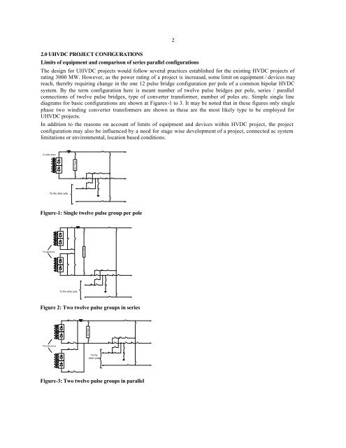
2.0 U<strong>HVDC</strong> PROJECT CONFIGURATIONS<br />
Limits <strong>of</strong> equipment <strong>and</strong> comparison <strong>of</strong> series parallel configurations<br />
The design for U<strong>HVDC</strong> projects would follow several practices established for the existing <strong>HVDC</strong> projects <strong>of</strong><br />
rating 3000 MW. However, as the power rating <strong>of</strong> a project is increased, some limit on equipment / devices may<br />
reach, thereby requiring change in the one 12 pulse bridge configuration per pole <strong>of</strong> a common bipolar <strong>HVDC</strong><br />
system. By the term configuration here is meant number <strong>of</strong> twelve pulse bridges per pole, series / parallel<br />
connections <strong>of</strong> twelve pulse bridges, type <strong>of</strong> converter transformer, number <strong>of</strong> poles etc. Simple single line<br />
diagrams for basic configurations are shown at Figures-1 to 3. It may be noted that in these figures only single<br />
phase two winding converter transformers are shown as these are the most likely type to be employed for<br />
U<strong>HVDC</strong> projects.<br />
In addition to the reasons on account <strong>of</strong> limits <strong>of</strong> equipment <strong>and</strong> devices within <strong>HVDC</strong> project, the project<br />
configuration may also be influenced by a need for stage wise development <strong>of</strong> a project, connected ac system<br />
limitations or environmental, location based conditions.<br />
12 pulse group<br />
DC Filter<br />
To the other pole<br />
Figure-1: Single twelve pulse group per pole<br />
12 pulse group<br />
DC Filter<br />
To the other pole<br />
Figure 2: Two twelve pulse groups in series<br />
DC Filter<br />
12 pulse group<br />
To the<br />
other pole<br />
Figure-3: Two twelve pulse groups in parallel