Technology and Development of 800 kV HVDC ... - Siemens
Technology and Development of 800 kV HVDC ... - Siemens
Technology and Development of 800 kV HVDC ... - Siemens

You also want an ePaper? Increase the reach of your titles
YUMPU automatically turns print PDFs into web optimized ePapers that Google loves.
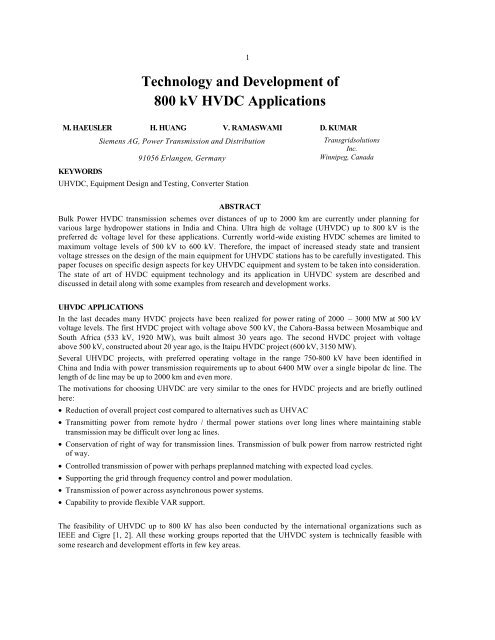
<strong>Technology</strong> <strong>and</strong> <strong>Development</strong> <strong>of</strong><br />
<strong>800</strong> <strong>kV</strong> <strong>HVDC</strong> Applications<br />
1<br />
M. HAEUSLER H. HUANG V. RAMASWAMI D. KUMAR<br />
KEYWORDS<br />
<strong>Siemens</strong> AG, Power Transmission <strong>and</strong> Distribution<br />
Transgridsolutions<br />
Inc.<br />
91056 Erlangen, Germany Winnipeg, Canada<br />
U<strong>HVDC</strong>, Equipment Design <strong>and</strong> Testing, Converter Station<br />
ABSTRACT<br />
Bulk Power <strong>HVDC</strong> transmission schemes over distances <strong>of</strong> up to 2000 km are currently under planning for<br />
various large hydropower stations in India <strong>and</strong> China. Ultra high dc voltage (U<strong>HVDC</strong>) up to <strong>800</strong> <strong>kV</strong> is the<br />
preferred dc voltage level for these applications. Currently world-wide existing <strong>HVDC</strong> schemes are limited to<br />
maximum voltage levels <strong>of</strong> 500 <strong>kV</strong> to 600 <strong>kV</strong>. Therefore, the impact <strong>of</strong> increased steady state <strong>and</strong> transient<br />
voltage stresses on the design <strong>of</strong> the main equipment for U<strong>HVDC</strong> stations has to be carefully investigated. This<br />
paper focuses on specific design aspects for key U<strong>HVDC</strong> equipment <strong>and</strong> system to be taken into consideration.<br />
The state <strong>of</strong> art <strong>of</strong> <strong>HVDC</strong> equipment technology <strong>and</strong> its application in U<strong>HVDC</strong> system are described <strong>and</strong><br />
discussed in detail along with some examples from research <strong>and</strong> development works.<br />
U<strong>HVDC</strong> APPLICATIONS<br />
In the last decades many <strong>HVDC</strong> projects have been realized for power rating <strong>of</strong> 2000 – 3000 MW at 500 <strong>kV</strong><br />
voltage levels. The first <strong>HVDC</strong> project with voltage above 500 <strong>kV</strong>, the Cahora-Bassa between Mosambique <strong>and</strong><br />
South Africa (533 <strong>kV</strong>, 1920 MW), was built almost 30 years ago. The second <strong>HVDC</strong> project with voltage<br />
above 500 <strong>kV</strong>, constructed about 20 year ago, is the Itaipu <strong>HVDC</strong> project (600 <strong>kV</strong>, 3150 MW).<br />
Several U<strong>HVDC</strong> projects, with preferred operating voltage in the range 750-<strong>800</strong> <strong>kV</strong> have been identified in<br />
China <strong>and</strong> India with power transmission requirements up to about 6400 MW over a single bipolar dc line. The<br />
length <strong>of</strong> dc line may be up to 2000 km <strong>and</strong> even more.<br />
The motivations for choosing U<strong>HVDC</strong> are very similar to the ones for <strong>HVDC</strong> projects <strong>and</strong> are briefly outlined<br />
here:<br />
• Reduction <strong>of</strong> overall project cost compared to alternatives such as UHVAC<br />
• Transmitting power from remote hydro / thermal power stations over long lines where maintaining stable<br />
transmission may be difficult over long ac lines.<br />
• Conservation <strong>of</strong> right <strong>of</strong> way for transmission lines. Transmission <strong>of</strong> bulk power from narrow restricted right<br />
<strong>of</strong> way.<br />
• Controlled transmission <strong>of</strong> power with perhaps preplanned matching with expected load cycles.<br />
• Supporting the grid through frequency control <strong>and</strong> power modulation.<br />
• Transmission <strong>of</strong> power across asynchronous power systems.<br />
• Capability to provide flexible VAR support.<br />
The feasibility <strong>of</strong> U<strong>HVDC</strong> up to <strong>800</strong> <strong>kV</strong> has also been conducted by the international organizations such as<br />
IEEE <strong>and</strong> Cigre [1, 2]. All these working groups reported that the U<strong>HVDC</strong> system is technically feasible with<br />
some research <strong>and</strong> development efforts in few key areas.
2<br />
2.0 U<strong>HVDC</strong> PROJECT CONFIGURATIONS<br />
Limits <strong>of</strong> equipment <strong>and</strong> comparison <strong>of</strong> series parallel configurations<br />
The design for U<strong>HVDC</strong> projects would follow several practices established for the existing <strong>HVDC</strong> projects <strong>of</strong><br />
rating 3000 MW. However, as the power rating <strong>of</strong> a project is increased, some limit on equipment / devices may<br />
reach, thereby requiring change in the one 12 pulse bridge configuration per pole <strong>of</strong> a common bipolar <strong>HVDC</strong><br />
system. By the term configuration here is meant number <strong>of</strong> twelve pulse bridges per pole, series / parallel<br />
connections <strong>of</strong> twelve pulse bridges, type <strong>of</strong> converter transformer, number <strong>of</strong> poles etc. Simple single line<br />
diagrams for basic configurations are shown at Figures-1 to 3. It may be noted that in these figures only single<br />
phase two winding converter transformers are shown as these are the most likely type to be employed for<br />
U<strong>HVDC</strong> projects.<br />
In addition to the reasons on account <strong>of</strong> limits <strong>of</strong> equipment <strong>and</strong> devices within <strong>HVDC</strong> project, the project<br />
configuration may also be influenced by a need for stage wise development <strong>of</strong> a project, connected ac system<br />
limitations or environmental, location based conditions.<br />
12 pulse group<br />
DC Filter<br />
To the other pole<br />
Figure-1: Single twelve pulse group per pole<br />
12 pulse group<br />
DC Filter<br />
To the other pole<br />
Figure 2: Two twelve pulse groups in series<br />
DC Filter<br />
12 pulse group<br />
To the<br />
other pole<br />
Figure-3: Two twelve pulse groups in parallel
3<br />
Limits due to transformer<br />
With increase in the rating <strong>of</strong> the project, the most likely reason for adopting two twelve pulse groups per pole<br />
would be the weight or size <strong>of</strong> converter transformer which may reach to values that it is no longer feasible to<br />
transport the converter transformer to the destined site. For a project <strong>of</strong> 4000 MW transmission capacity under<br />
bipolar mode, the size <strong>of</strong> even a single phase two winding transformer is about 394 MVA. This transformer may<br />
be about 12x4.5x5 meter, weighing around 400 tons <strong>and</strong> might already be approaching the limits <strong>of</strong><br />
transportation, which would depend upon the specific location <strong>of</strong> the converter terminals <strong>and</strong> influenced by the<br />
strengths <strong>of</strong> bridges en route, limits <strong>of</strong> roads <strong>and</strong> rails etc.<br />
Limits due to thyristor<br />
A U<strong>HVDC</strong> project is generally required to meet steady state as well as overload conditions as determined by<br />
planners. The employed thyristors must be able to meet these conditions. With the present day capacity <strong>of</strong> about<br />
4 kA for thyristors the overload capacity is not a problem even with series connected valves <strong>of</strong> about 6000 MW<br />
capacity bipolar project which has a rated current <strong>of</strong> 3.75 amps at <strong>800</strong> <strong>kV</strong>. With higher rating projects or lower<br />
rated voltage a parallel arrangement <strong>of</strong> bridges or a use <strong>of</strong> bigger diameter thyristor may be considered.<br />
Comparison <strong>of</strong> Series / Parallel arrangement<br />
When the need for two twelve pulse groups arise, generally the series group may tend to be adopted mainly<br />
because the series groups maintain balance in the two pole currents even during an outage <strong>of</strong> a series group <strong>and</strong><br />
hence there are potentially no ground currents when one <strong>of</strong> the two series groups is out. In case <strong>of</strong> parallel<br />
groups the current in a pole is the addition <strong>of</strong> currents in each group, <strong>and</strong> hence, on outage <strong>of</strong> a group there<br />
would be an unbalance in the two pole currents giving rise to ground currents.<br />
With parallel groups, the currents in each group is only half <strong>of</strong> the pole current <strong>and</strong> there would be sufficient<br />
overload capacity left in the thyristor for the maximum size <strong>of</strong> projects under consideration. Therefore very high<br />
capacity links may find application <strong>of</strong> parallel groups on account <strong>of</strong> current rating <strong>of</strong> thyristors.<br />
On outage <strong>of</strong> group, the line losses would be considerably lower in case <strong>of</strong> a parallel group as compared to<br />
series group under similar outage, on account <strong>of</strong> fact that the pole current reduces to half in case <strong>of</strong> a parallel<br />
group outage.<br />
The parallel groups are highly adaptable to stage wise development. The parallel groups can easily be added to<br />
an existing pole with minimum <strong>of</strong> disturbance during commissioning. With parallel groups each group can<br />
easily be located at different places far from each other as per requirement or to reduce the cost <strong>of</strong> ac<br />
transmission system that connects at either end <strong>of</strong> the transmission for collecting <strong>and</strong> delivering power at<br />
different locations in the grid. This may have several system related advantages with regard to maintaining<br />
voltage pr<strong>of</strong>ile, reliability, stability etc.<br />
From the discussion above it is seen that the operating voltage, current <strong>and</strong> configuration <strong>of</strong> a project will be<br />
strongly influenced by the amount <strong>of</strong> power that has to be transmitted, location <strong>and</strong> the connected ac systems.<br />
FOCAL POINTS<br />
The major focal points for a U<strong>HVDC</strong> project briefly discussed in the following sections are:<br />
• System Integration<br />
• Insulation Coordination<br />
• Converter Transformer <strong>and</strong> Bushings<br />
• Wall Bushings<br />
• DC Yard Equipment
4<br />
System Integration<br />
Due to the large amount <strong>of</strong> real <strong>and</strong> reactive powers associated with U<strong>HVDC</strong> projects each <strong>of</strong> the following<br />
aspects needs to be examined in detail <strong>and</strong> ensured:<br />
1. the sending <strong>and</strong> receiving ac systems have adequate (transmission) capacity, taking into considerations the<br />
outage criteria <strong>of</strong> the system planner.<br />
2. there is an adequate effective short circuit ratio for operation up to overload levels <strong>and</strong> under the outage<br />
conditions in the ac network. Strategies to cope with abnormal situations where effective short circuit ratio<br />
may reduce below at which project is designed.<br />
3. suitable reactive power support under steady state <strong>and</strong> dynamic conditions.<br />
4. ensure voltage / power stability under all operating conditions. Steady state, temporary <strong>and</strong> transient<br />
overvoltages beyond the specified values be avoided under unexpected conditions <strong>and</strong> following faults.<br />
5. avoid low order resonance under all conditions such as maximum allowed reactive power support <strong>and</strong> low<br />
short circuit level conditions<br />
6. for multi infeed <strong>HVDC</strong> configurations possibilities <strong>of</strong> any adverse interactions among <strong>HVDC</strong> or actively<br />
controlled projects should be examined <strong>and</strong> avoided.<br />
7. system stability must be maintained for a group / pole outage as per specifications. System stability is also to<br />
be maintained following specified disturbances, faults <strong>and</strong> outages in the ac system.<br />
Insulation Coordination<br />
With respect to the U<strong>HVDC</strong> projects it would be important to reduce the size <strong>of</strong> equipment to the extent<br />
possible so that mechanical duties <strong>and</strong> costs are reduced <strong>and</strong> reliability is increased. This can be achieved by<br />
controlling the steady state, temporary, transient <strong>and</strong> lightning overvoltages with the help <strong>of</strong> system design,<br />
control systems, operating logic <strong>and</strong> arresters.<br />
The utilities have to play a major role in this by formulating a specification that is not overly pessimistic in<br />
assumptions about variations <strong>of</strong> system parameters such as short circuit levels <strong>and</strong> operating voltage range for<br />
determining the rating <strong>of</strong> equipment or for determining the overvoltages in the system. Similarly, it would be<br />
prudent to judiciously select the air clearances <strong>and</strong> creepage distances.<br />
Since the insulation withst<strong>and</strong> levels are directly dependent upon the protective levels provided by the arresters,<br />
the use <strong>of</strong> ZnO arresters would be very important to limit these overvoltages at precise levels for equipment<br />
such as converter transformers, smoothing reactors <strong>and</strong> valves. This may require placement <strong>of</strong> arresters near the<br />
valve side windings <strong>of</strong> converter transformer in the upper bridge or across smoothing reactors. An indicative<br />
placement <strong>of</strong> arresters for a series connected U<strong>HVDC</strong> scheme is shown below at Figure-7.<br />
Figure – 7: Placement <strong>of</strong> arresters in a series connected U<strong>HVDC</strong> scheme<br />
This scheme is basically similar to the existing <strong>HVDC</strong> scheme with an addition <strong>of</strong> arrester for the converter<br />
transformer secondary side connected to the high voltage dc side. The smoothing reactors have also been placed
5<br />
on the neutral bus to reduce the ripples on dc voltage at the dc high voltage bus. The arresters shown across<br />
smoothing reactors are also not generally employed in normal <strong>HVDC</strong> schemes but are indicated here.<br />
Following insulation levels for dc equipment are expected.<br />
Table 2 : Expected Insulation Levels<br />
Equipment / Location Units SIWL LIWL<br />
Transformer valve side, connected in the upper bridge <strong>kV</strong> 1600 1<strong>800</strong><br />
Transformer Valve side, other in the upper bridge <strong>kV</strong> 1300 1550<br />
DC yard equipment, line side <strong>of</strong> smoothing reactor <strong>kV</strong> 1600 1900<br />
DC yard equipment, valve hall side <strong>of</strong> smoothing reactor <strong>kV</strong> 1600 1<strong>800</strong><br />
External Insulation <strong>of</strong> the Equipment<br />
Designing equipment for correct external insulation means to take care <strong>of</strong> proper<br />
flash distances <strong>and</strong><br />
creepage distances<br />
<strong>of</strong> the equipment housings.<br />
Flash distances<br />
Required flash distances determine the axial length <strong>of</strong> the equipment. Flash distances can be calculated fairly<br />
well based on the specified insulation levels for the equipment. For U<strong>HVDC</strong> equipment the switching impulse<br />
level will become the dimensioning factor. DC voltages are not decisive with respect to the flash distance.<br />
Corrections will be included for equipment to be installed at higher altitudes above sea level. Flash distances<br />
increase more than linearly with increasing switching impulse voltages. Finally the correct design will be<br />
verified by corresponding type tests <strong>of</strong> the equipment.<br />
Creepage distances<br />
As far as equipment will be installed outdoors the external insulation with respect to creepage distances is more<br />
complex compared to the flash distance as it severely depends on environmental <strong>and</strong> weather conditions, i.e. on<br />
the degree <strong>of</strong> pollution collected on the equipment <strong>and</strong> wetting conditions (rain, fog etc.) <strong>of</strong> the polluted housing<br />
surfaces. It must be accepted that pollution combined with wetting as it occurs under service conditions can<br />
hardly be determined for the purpose <strong>of</strong> test conditions. Artificial pollution tests as per the st<strong>and</strong>ards can only<br />
show the capability <strong>of</strong> a housing to cope electrically with a certain degree <strong>of</strong> completely wetted pollution.<br />
Another important role concerning the pollution flashover performance <strong>of</strong> housings is played by the shed pr<strong>of</strong>ile<br />
<strong>of</strong> the insulators. From experience two types <strong>of</strong> shed forms should be taken into consideration for DC<br />
application which are the deep under-rib <strong>and</strong> the alternate shed pr<strong>of</strong>ile. A decisive property <strong>of</strong> a shed pr<strong>of</strong>ile is<br />
the ability to prevent wetting <strong>of</strong> the pollution, i.e. to maintain the effectiveness <strong>of</strong> the creepage distance on the<br />
surface as much as possible. Publications show that there is no straightforward advantage for one <strong>of</strong> the shed<br />
types. A well designed alternating shed pr<strong>of</strong>ile can perform as good as a deep under-rib pr<strong>of</strong>ile. The decisive<br />
underst<strong>and</strong>ing seems to be that an improvement in pollution performance cannot be achieved by only increasing<br />
the creepage distance without increasing the axial length <strong>of</strong> the housing. In other words: increasing the creepage<br />
distance by increasing only the overhang <strong>of</strong> the sheds <strong>and</strong>/or reducing the shed spacing is not effective. Hence,<br />
increasing the creepage distance must go coincidently with increasing the axial length <strong>of</strong> the housing.<br />
This shows that general rules to select the appropriate equipment housing in order to prevent external flashovers<br />
resulting from pollution <strong>and</strong> wetting conditions cannot be established. Site conditions, if available, with respect<br />
to amount <strong>of</strong> pollution collected on the housing <strong>and</strong> the ability <strong>of</strong> natural cleaning should be taken into<br />
consideration, as well.<br />
Such reflections are mainly applicable for porcelain type equipment housings. Alternative solutions are known<br />
<strong>and</strong> have to be looked at.<br />
From long-term experience with 500 <strong>kV</strong> DC outdoor equipment one alternative solution is housings with<br />
hydrophobic type <strong>of</strong> surfaces. The hydrophobic properties need not to be explained in detail here.<br />
Hydrophobicity is an intrinsic property <strong>of</strong> silicone rubber <strong>and</strong> is not achieved on any long term by additives or
6<br />
surface treatment. Elements <strong>of</strong> the silicone rubber which cause hydrophobicity diffuse into contamination layers<br />
on the surface <strong>of</strong> the housing <strong>and</strong> thus are transferring this property to the contamination. A further advantage is<br />
that hydrophobic material prevents the formation <strong>of</strong> larger coherent wet zones on the surface under rain <strong>and</strong><br />
humidity. This is an important precondition in order to maintain the effectiveness <strong>of</strong> the creepage distance<br />
against pollution flashovers. Silicone rubber housings having such advantages are available <strong>and</strong> successfully in<br />
service in DC stations since a very long time. From experience with existing projects the specific creepage<br />
distance <strong>of</strong> composite insulators can even be reduced by up to 25% compared to that <strong>of</strong> porcelain insulators.<br />
However, for some equipment porcelain type insulators are advantageous because <strong>of</strong> mechanical reasons. This<br />
refers to the support insulators in the DC yard <strong>and</strong> for air-insulated smoothing reactors <strong>and</strong> to the insulators <strong>of</strong><br />
disconnect switches. Without taking remedy measures for such U<strong>HVDC</strong> equipment pollution flashovers cannot<br />
be excluded. Alternatives for improvement are needed. One possibility could be to coat the porcelain housings<br />
with hydrophobic material. This technology has been improved quite a lot in recent years. Yet, details need still<br />
to be verified especially the long-term behavior <strong>of</strong> the coating material.<br />
Another alternative for post insulators under investigation is in a very early stage. The idea is to use porcelain as<br />
core material providing sufficient mechanical strength <strong>and</strong> to equip this core with silicone rubber sheds, as it is<br />
done with composite housings (silicone rubber sheds on epoxy resin tube, mechanically reinforced with fiber<br />
glass).<br />
The method <strong>of</strong> booster sheds is also a well known possibility to improve the performance <strong>of</strong> porcelain insulators<br />
under DC stresses.<br />
As far as converter valves <strong>and</strong> associated equipment are concerned the design <strong>of</strong> creepage distance is not a<br />
problem as such equipment will be installed indoors in the converter valve hall like in the existing projects. The<br />
valve hall provides a controlled environment. For U<strong>HVDC</strong> equipment inside the valve hall the same specific<br />
creepage distance can be selected as for the existing 500 <strong>kV</strong> DC equipment.<br />
Consistent to this it seems reasonable to consider the installation <strong>of</strong> U<strong>HVDC</strong> yard equipment also indoors in a<br />
so-called DC hall. If this alternative is followed the DC hall has to be designed very thoroughly with the<br />
objective <strong>of</strong> achieving defined low pollution <strong>and</strong> humidity conditions inside the hall, conditions which do not<br />
depend on the outside environment. For indoor installation the specific creepage distance can be reduced to<br />
some extent compared to outdoor installation.<br />
Relative to existing equipment it can be stated that specific creepage distances neither for outdoor nor for indoor<br />
installation need not to be increased for U<strong>HVDC</strong> equipment in order to ensure safe performance against<br />
pollution flashovers. Furthermore, higher altitudes above sea level are no issue for the creepage distance. If the<br />
flash distance <strong>of</strong> the equipment is properly corrected with respect to the altitude above sea level influences <strong>of</strong><br />
the altitude on the creepage distance, should any exist, will be covered.<br />
Converter Transformer <strong>and</strong> Transformer Bushings<br />
The operating conditions <strong>of</strong> <strong>HVDC</strong> converter transformer differ from conventional ac transformers in several<br />
ways such as presence <strong>of</strong> harmonic currents, possible small amount <strong>of</strong> dc currents, complex voltage waveform<br />
that has ac <strong>and</strong> dc components on the valve side windings, cleat leads <strong>and</strong> bushings having dc component<br />
stresses, stringent mechanical duties due to commutation process etc. Due to the combined ac <strong>and</strong> dc stresses<br />
the internal insulation system design comprise <strong>of</strong> considerable amount <strong>of</strong> paper insulation in addition to oil. The<br />
converter transformers may also have considerable duty on account <strong>of</strong> reactive power consumption by <strong>HVDC</strong><br />
projects. As a result the size <strong>and</strong> weight <strong>of</strong> converter transformer is large compared to normal ac transformer <strong>of</strong><br />
equivalent rating.<br />
The valve windings <strong>of</strong> the converter transformers connected with the upper six pulse group would see<br />
maximum rated dc voltage <strong>of</strong> transmission which may be +/- <strong>800</strong> <strong>kV</strong> plus the allowed tolerances. These<br />
windings may also see overvoltages originating from dc as well ac side. Thus the bushings, leads <strong>and</strong> winding<br />
insulation shall have to be rated for high voltage resulting in large dimensions for these equipment. It will be<br />
very important to uniformly distribute the steady state <strong>and</strong> transient voltage stresses across the insulation within<br />
the transformer <strong>and</strong> also in bushings.
7<br />
Figure 4 : A two winding converter transformer for a +/- 500 <strong>kV</strong> dc project<br />
In line with the generally acceptable practice for modern high capacity projects dry type bushings with<br />
composite insulation are expected.<br />
Increased insulation levels in combination with larger rated power may lead to new solutions for the transformer<br />
design. A possible approach may<br />
be splitting up <strong>of</strong> the secondary windings <strong>and</strong> a new design <strong>of</strong> the connections between windings <strong>and</strong> bushings<br />
on the valve side as indicated in Figure-5. This part <strong>of</strong> the transformer will be crucial for its transportation data.<br />
As an example, transformer rating <strong>and</strong> preliminary shipping data for a system rating <strong>of</strong> 5000 MW with <strong>800</strong> <strong>kV</strong><br />
DC are as follows:<br />
Table-1: Typical parameters for converter U<strong>HVDC</strong><br />
transformer <strong>of</strong> 5000 MW rating<br />
one 12p-group two 12p-groups<br />
per pole per pole<br />
rating (MVA) 494 247<br />
length / width / 13.3 / 4.3 / 5.0 9.4 / 4.0 / 4.9<br />
height(m)<br />
weight (t) 480 300<br />
These data refer to the unit <strong>of</strong> the highest DC voltage level at the sending end; all other units <strong>of</strong> the system will<br />
not exceed such dimensions <strong>and</strong> weights. With respect to typical limits which might exist in case <strong>of</strong> railway<br />
transportation it is quite evident that improvement is required especially as far as the transformer width is<br />
Figure-5: Preliminary outline Drawing U<strong>HVDC</strong> Converter<br />
Transformer
8<br />
concerned. If railway transportation is the only possibility, then in case <strong>of</strong> one 12-pulse group per pole<br />
arrangement additional investigations have to be done to achieve adequate transport conditions.<br />
Some important points that require attention in converter transformer are summarized below:<br />
• to ensure uniform distribution <strong>of</strong> voltage for the leads taking into considerations the effects <strong>of</strong> harmonic<br />
currents <strong>and</strong> harmonic impedance<br />
• to ensure that radial stress on components e.g. bushings is within the design limits under all operating<br />
conditions including the effects due to external pollution if these are exposed to atmosphere.<br />
• achieve a balance between mechanical duties <strong>and</strong> electrical requirements. For example, the creepage distance<br />
should be chosen such that it meets the electrical requirements but does not result in unduly large mechanical<br />
dimensions.<br />
• to manage external electrical stresses by proper design <strong>of</strong> electrode, shape <strong>of</strong> corona rings etc.<br />
• the use <strong>of</strong> considerable paper insulation should not affect the thermal design <strong>of</strong> the transformer <strong>and</strong> proper<br />
cooling <strong>of</strong> all parts must be ensured.<br />
DC Wall Bushing<br />
Doubtless, the existing technology <strong>of</strong> wall bushings provides the best solution for U<strong>HVDC</strong> applications.<br />
Existing technology means composite housing with silicone rubber sheds for external insulation <strong>and</strong> internally<br />
with condenser core <strong>of</strong> oil-free resin impregnated paper <strong>and</strong> SF6 for insulation between core <strong>and</strong> inner surface<br />
<strong>of</strong> the housing. Both parts <strong>of</strong> the wall bushing, indoors <strong>and</strong> outdoors, are <strong>of</strong> the same design <strong>and</strong> are connected<br />
by means <strong>of</strong> a SF6 filled duct. This type <strong>of</strong> wall bushing is successfully in operation since more than 15 years<br />
under various pollution conditions.<br />
Figure-6 shows an outline drawing <strong>of</strong> a wall bushing as suitable for U<strong>HVDC</strong> applications.<br />
Figure – 6: DC Wall Bushing<br />
Most important for this bushing technology is the appropriate coordination between internal <strong>and</strong> external<br />
insulation. The manufacturing capabilities in terms <strong>of</strong> length <strong>of</strong> housings <strong>and</strong> length <strong>of</strong> condenser cores play an<br />
important part in this context. Another area <strong>of</strong> concern with wall bushings is the mechanical stresses which<br />
needs thorough investigations.<br />
Further, it has been observed that the wall bushings require particular attention in their mounting since these are<br />
particularly prone to uneven wetting during rain which increases the risk <strong>of</strong> flashovers. For U<strong>HVDC</strong> projects, it<br />
would be necessary to check this aspect carefully with regard to the above mentioned radial stresses <strong>and</strong><br />
probability <strong>of</strong> external flashover. The hydrophobic silicon material used for these bushings has proved to be is<br />
extremely effective in mitigating the problem <strong>of</strong> flashovers.<br />
Proper design <strong>of</strong> external clamps, connectors, corona rings etc would be essential.<br />
DC Switchyard Equipment<br />
The main DC yard equipment that would require special attention is the following:<br />
Smoothing Reactor<br />
Both, air- <strong>and</strong> oil-type smoothing reactors, have to be considered. Know-how <strong>and</strong> experience for both<br />
technologies are available.<br />
Oil-type Smoothing Reactor<br />
Two different arrangements are sown in Figure-8 <strong>and</strong> 9 for indoor <strong>and</strong> outdoor arrangements.<br />
For the outdoor part <strong>of</strong> this smoothing reactor bushing similar requirements as for the wall bushings regarding<br />
pollution conditions exist. Preliminary shipping data for a 300 mH, <strong>800</strong> <strong>kV</strong> smoothing reactor can be given as:<br />
length / width / height (m) 5.5 / 4.0 / 4.8<br />
weight (t) 150.
9<br />
Fig.-8: Oil-type Smoothing Reactor (Indoor)<br />
Fig.-9: Oil-type Smoothing Reactor (Outdoor)<br />
Air-type Smoothing Reactor<br />
The operating dc current determines the largest smoothing reactor coil size which can be manufactured. As an<br />
example for a dc current <strong>of</strong> 3.3 kA a maximum coil size <strong>of</strong> approx. 100 mH is feasible. Fig.-10 shows the<br />
preliminary drawing <strong>of</strong> such an air-type smoothing reactor suitable for U<strong>HVDC</strong> application. The available<br />
technology <strong>and</strong> know-how for the coils <strong>of</strong> existing <strong>HVDC</strong> schemes can be fully used for U<strong>HVDC</strong> application.<br />
Assuming typical total smoothing reactor sizes <strong>of</strong> 250 to 350 mH a series connection <strong>of</strong> several coils might be<br />
needed as illustrated in Fig.-11. For reasons stated above parts <strong>of</strong> the coils might also be installed at the neutral<br />
bus.<br />
Porcelain support insulators are the main issues to be solved for air-type smoothing reactors.
10<br />
Fig.10: U<strong>HVDC</strong> Dry-type Smoothing Reactor Coil<br />
Fig. 11: Example for Series Connection <strong>of</strong> Dry-Type Smoothing Reactor Coils<br />
DC Switchgear<br />
Disconnect Switch<br />
Disconnect switches are typically designed based on porcelain insulators specifically because <strong>of</strong> mechanical<br />
stresses resulting from operation. Such stresses are even increased if grounding switches are directly attached to<br />
the disconnect switch. However, designs based on composite insulators are currently under investigation. Fig.-<br />
12 shows the preliminary drawing <strong>of</strong> an U<strong>HVDC</strong> double break disconnect switch.
11<br />
Fig. 12: U<strong>HVDC</strong> Double Break Disconnect Switch<br />
Bypass Switch<br />
If a transmission system consists <strong>of</strong> two 12-pulse groups per pole breakers <strong>and</strong> disconnect switches are needed<br />
for each 12-pulse group. In case <strong>of</strong> failures related to a 12-pulse group <strong>and</strong> its associated equipment this group<br />
can be by-passed with the other 12-pulse group <strong>of</strong> the pole still in operation. Regarding the disconnect switches<br />
needed for the by-pass operation the section above is relevant.<br />
The breaker to be used as bypass switch will be a proven st<strong>and</strong>ard AC breaker adapted for the DC application. It<br />
should be kept in mind that for the voltage-wise higher 12-pulse group the voltage between terminals is the<br />
group voltage whereas the voltage to ground is the U<strong>HVDC</strong> bus voltage.<br />
The steady state DC voltage capability between the terminals <strong>of</strong> the bypass switch, i. e. the DC voltage<br />
capability <strong>of</strong> the interrupting units is another very important subject which needs further investigation. This is<br />
part <strong>of</strong> the modification for DC application mentioned before.<br />
DC Yard Bus Work, Conductors<br />
In addition to current ratings <strong>of</strong> the diameters <strong>of</strong> dc bus work, conductors <strong>and</strong> their bundling would be<br />
influenced by operating voltage, corona, RI, audible noise, electric field considerations etc.<br />
CONCLUSIONS<br />
From above discussions general conclusions read as follows:<br />
The configuration <strong>of</strong> a U<strong>HVDC</strong> project would be decided from the rating <strong>and</strong> system considerations which<br />
influence converter transformer size <strong>and</strong> overload capability <strong>of</strong> the project<br />
From the main equipment point <strong>of</strong> view UHDC systems <strong>of</strong> up to <strong>800</strong> <strong>kV</strong> are technically feasible. In general<br />
U<strong>HVDC</strong> equipment can be designed <strong>and</strong> manufactured based on existing technology <strong>and</strong> know-how. For most<br />
<strong>of</strong> the station equipment only some or even no R&D is anticipated. However, converter transformers <strong>and</strong><br />
bushings need more thorough R&D.<br />
External insulation <strong>of</strong> U<strong>HVDC</strong> equipment, especially for outdoor installation has been identified as one <strong>of</strong> the<br />
key issues.<br />
REFERENCES<br />
1. <strong>HVDC</strong> Converter Stations for Voltages Above ±600 <strong>kV</strong>, WG 14.32, CIGRE Publication, December 2002.
2. <strong>HVDC</strong> Converter Stations for Voltages Above ±600 <strong>kV</strong>, - EPRI EL-3892-Project 2115-4 Final Report –<br />
Feb 1985.<br />
12<br />
BIOGRAPHICAL DETAILS OF THE AUTHORS<br />
Marcus Haeusler, born in 1966, received his Dipl.-Ing. Degree in Electrical Engineering from University <strong>of</strong><br />
Karlsruhe, Germany, in 1992. Since he joined <strong>Siemens</strong> AG in 1992, he has been working on <strong>HVDC</strong> system<br />
engineering for many <strong>HVDC</strong> projects world wide.<br />
Ramaswami Velpanur, born in 1946 received his Bachelors Degree in Electrical Engineering from the<br />
University <strong>of</strong> Bangalore in 1969. He has been working in the <strong>HVDC</strong> field since 1980, first with Brown Boveri<br />
& Cie <strong>and</strong> then with <strong>Siemens</strong><br />
Hartmut Huang, born in 1963, received his Dipl.-Ing. degree <strong>and</strong> PhD in Electrical Engineering from<br />
University <strong>of</strong> Braunschweig, Germany, in 1986 <strong>and</strong> 1992, respectively. Since he joined <strong>Siemens</strong> AG in 1992,<br />
he has been working on <strong>HVDC</strong> system engineering for many <strong>HVDC</strong> projects world wide. Currently he is<br />
manager <strong>of</strong> <strong>HVDC</strong> system engineering department at <strong>Siemens</strong> Power Transmission <strong>and</strong> Distribution Group.<br />
Devinder Kumar, born 1958, received his B.Tech degree in Electrical Engineering from IIT Delhi, in 1980.<br />
He joined NTPC, India in 1980 <strong>and</strong> later POWERGRID, India in 1990. Since 2005 he has been working with<br />
TransGrid Solutions Inc., Canada. He has worked on <strong>HVDC</strong> projects in the areas <strong>of</strong> planning, specification<br />
preparation, studies, <strong>and</strong> operation & maintenance.