P40000 Catalog - Kube Engineering
P40000 Catalog - Kube Engineering
P40000 Catalog - Kube Engineering

You also want an ePaper? Increase the reach of your titles
YUMPU automatically turns print PDFs into web optimized ePapers that Google loves.
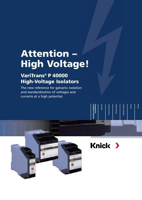
Attention –<br />
High Voltage!<br />
VariTrans ® P 40000<br />
High-Voltage Isolators<br />
The new reference for galvanic isolation<br />
and standardization of voltages and<br />
currents at a high potential.<br />
Isolation Amplifiers<br />
Transmitters<br />
Indicators<br />
Process Analyzers<br />
Portable Meters<br />
Laboratory Meters<br />
Sensors<br />
Fittings
Isolation Amplifiers<br />
Transmitters<br />
Indicators<br />
Process Analyzers<br />
Portable Meters<br />
Laboratory Meters<br />
Sensors<br />
Fittings<br />
High-voltage isolation with the<br />
new TransShield ® technology<br />
VariTrans ® P 40000<br />
Working voltages up to 3600 V AC/DC and test voltage<br />
up to 15 kV AC, calibrated range selection and VariPower ®<br />
broad-range power supply, extreme efficiency compressed<br />
in compact modular housing – with a unique combination<br />
of product features Knick’s new VariTrans ® P 40000 series<br />
shows what is possible today in isolators with high isolation<br />
capability.<br />
Mode Rejection) is defined for<br />
the corresponding data specification.<br />
It describes the quotient<br />
between differential DC gain and<br />
common-mode gain of a transient<br />
interference signal with a<br />
rise speed of 1000 V/µs.<br />
The universal devices transmit<br />
voltages and currents, ensure<br />
galvanic isolation with high insulation<br />
and convert the input signal<br />
with high accuracy into a standardized<br />
output signal.<br />
■ TransShield ® technology<br />
In this series, Knick relies on the<br />
newly developed TransShield ®<br />
technology which compared to<br />
conventional designs enables<br />
very compact high-voltage<br />
transformers with low leakage.<br />
Thanks to the resulting space<br />
advantage, the P 41000 shunt<br />
isolators could be implemented<br />
in an only 22.5 mm wide modular<br />
housing.<br />
Another substantial advantage<br />
of this technology: high transient<br />
overvoltages (common-mode<br />
interference) are reliably isolated<br />
and cause hardly any measurement<br />
errors at the output. The<br />
term T-CMR (Transient Common<br />
The VariTrans ® P 40000 series<br />
devices achieve a T-CMR of<br />
115 dB here; the common-mode<br />
rejection for 50 Hz disturbances<br />
is 150 dB.<br />
■ Calibrated range<br />
selection<br />
A highly functional and unique<br />
feature of high voltage isolators<br />
is the calibrated range selection:<br />
16 input/output signal combinations<br />
can be easily selected with<br />
a rotary coding switch on the<br />
front of the device. Tedious onsite<br />
adjustment using a screwdriver,<br />
calibrator or multimeter is<br />
no longer required. There are no<br />
drift problems due to instable<br />
trim components – e. g. potentiometers.<br />
Easy scalability of the range<br />
selection supports customized<br />
solutions; optimally adapted to<br />
the respective application, up<br />
to 16 tailor-made signal combinations<br />
can be implemented in<br />
one device.<br />
2
■ Integrated broad-range<br />
power supply<br />
Maximum flexibility and direct<br />
added value for the user is also<br />
provided by the integrated 20 to<br />
253 V AC/DC broad-range power<br />
supply. This ensures trouble-free<br />
operation with alternating or direct<br />
voltages everywhere in the<br />
world and provides for maximum<br />
safety even in unstable power<br />
supply networks. Installation is<br />
also easy and safe: Incorrect<br />
assignment of the mains voltage<br />
is practically excluded; expensive<br />
downtimes and repairs<br />
during commissioning are<br />
avoided.<br />
■ Maximum safety<br />
Vacuum encapsulation protects<br />
the circuitry against environmental<br />
influences and reliably ensures<br />
the high insulation strength<br />
required for working voltages up<br />
to 3600 V AC/DC. At the same<br />
time, not only the safety regulations<br />
stipulated in EN 61010-1<br />
but also the regulations of the<br />
EN 50124-1 standard (insulation<br />
coordination for railway applications)<br />
are observed. Thus the<br />
isolators are excellently equipped<br />
for galvanically isolated measurements<br />
in railway transportation<br />
technologies up to a voltage of<br />
3000 V DC.<br />
To prove insulation according to<br />
specification, a 100 % routine<br />
test is carried out with a voltage<br />
of 15 kV AC (fixed range models)<br />
and 10 kV AC (switchable<br />
models) respectively. The vacuum<br />
encapsulation technology<br />
employed by Knick provides<br />
maximum long-term protection<br />
against aggressive environmental<br />
influences, shock, and vibrations.<br />
■ Impressive functionality<br />
Also in the new VariTrans ®<br />
P 40000 series, the switching<br />
technology and device construction<br />
ensure excellent transmission<br />
quality that is reflected, among<br />
other things, in the zero stability,<br />
linearity, long-term stability, frequency<br />
response and immunity<br />
to interference. Thanks to the<br />
high cut-off frequency of the<br />
devices, the signal form on the<br />
input is reproduced on the output<br />
without distortion. Fast changes<br />
in the input signal are converted<br />
almost without delay into a corresponding<br />
change in the output<br />
signal.<br />
In the input signals, the new<br />
Knick high-voltage isolators provide<br />
a wide measurement range:<br />
from a millivolt range – for example<br />
for the measurement of large<br />
currents via shunt resistances –<br />
to high voltages in the kilovolt<br />
range; currents up to 5 A can be<br />
measured directly. Analog unipolar<br />
and bipolar (standard) signals<br />
are available at the output of the<br />
high voltage isolators. The planner<br />
or user can select any combination<br />
from the input and output<br />
signal and thus take into account<br />
the individual conditions of use<br />
flexibly.<br />
3
Isolation Amplifiers<br />
Transmitters<br />
Indicators<br />
Process Analyzers<br />
Portable Meters<br />
Laboratory Meters<br />
Sensors<br />
Fittings<br />
VariTrans ® P 40000<br />
High-Voltage Isolators<br />
■ Versatile applications<br />
The VariTrans ® P 40000 series is<br />
interesting for applications in the<br />
monitoring and control of electric<br />
drive systems that can be operated<br />
with medium or high voltages.<br />
Further applications can be found<br />
in railway power supply; main<br />
tasks include voltage monitoring<br />
or measurement of operating<br />
and fault currents in direct current<br />
switchgear.<br />
This device class offers previously<br />
unknown efficiency and<br />
flexibility which support the user<br />
optimally in the development of<br />
his product or system solution.<br />
■ Optimized series<br />
For different measuring ranges<br />
and standard requirements, three<br />
series in 22.5 to 67.5 mm wide<br />
housings are offered – either as<br />
variants with fixed settings or<br />
as switchable version with calibrated<br />
range selection.<br />
The working voltage for fixed<br />
range models is 3600 V AC/DC<br />
(test voltage 15 kV AC), and<br />
2200 V AC/DC (test voltage<br />
10 kV AC) for switchable models.<br />
The impressed 0 to ±20 mA,<br />
0 to ±10 V or 4 to 20 mA signals<br />
are available at the output.<br />
Customer-specific devices can be<br />
equipped with up to 16 freely<br />
selectable signal combinations.<br />
The facts:<br />
Universal usability: input 60 mV up<br />
to 3600 V or 100 mA up to 5 A<br />
–––––––––––––––––––––––––––––––––––––––––––––––––––––––––––––––––––<br />
New TransShield ® technology<br />
enables extremely compact<br />
modular housing<br />
–––––––––––––––––––––––––––––––––––––––––––––––––––––––––––––––––––<br />
Working voltages up to<br />
3600 V AC/DC<br />
–––––––––––––––––––––––––––––––––––––––––––––––––––––––––––––––––––<br />
Protection against electrical shock<br />
through Safe Isolation up to<br />
1800 V AC/DC<br />
–––––––––––––––––––––––––––––––––––––––––––––––––––––––––––––––––––<br />
Increased test voltage 15 kV AC<br />
–––––––––––––––––––––––––––––––––––––––––––––––––––––––––––––––––––<br />
Excellent transmission properties:<br />
– gain error only to 0.1 %<br />
– cut-off frequency > 5 kHz<br />
– rise time T90 < 0.1 ms<br />
–––––––––––––––––––––––––––––––––––––––––––––––––––––––––––––––––––<br />
Practically no influence from<br />
common-mode voltages:<br />
CMRR > 150 dB<br />
–––––––––––––––––––––––––––––––––––––––––––––––––––––––––––––––––––<br />
High immunity to transient<br />
interferences: T-CMR >115 dB<br />
–––––––––––––––––––––––––––––––––––––––––––––––––––––––––––––––––––<br />
Tremendous flexibility provided by<br />
– calibrated switching of up to<br />
16 input/output ranges<br />
– up to 16 customer-specific<br />
measuring ranges<br />
– VariPower ® 20 V to 253 V<br />
AC/DC broad-range power<br />
supply unit<br />
–––––––––––––––––––––––––––––––––––––––––––––––––––––––––––––––––––<br />
Reliable function even with<br />
unstable supply<br />
–––––––––––––––––––––––––––––––––––––––––––––––––––––––––––––––––––<br />
No destruction in the event of<br />
erroneously incorrect mains voltage<br />
Switchable types reduce variety of<br />
versions, thus saving storage costs<br />
–––––––––––––––––––––––––––––––––––––––––––––––––––––––––––––––––––<br />
Robust thanks to vacuum encapsulation<br />
4
Suitable for direct current railway<br />
systems up to 3000 V DC<br />
–––––––––––––––––––––––––––––––––––––––––––––––––––––––––––––––––––<br />
Mechanically stable for operation<br />
on ships, rail vehicles and land<br />
crafts<br />
–––––––––––––––––––––––––––––––––––––––––––––––––––––––––––––––––––<br />
Warranty: 5 years<br />
–––––––––––––––––––––––––––––––––––––––––––––––––––––––––––––––––––<br />
Warranty: 5 years<br />
Defects occurring within 5 years<br />
from delivery date shall be remedied<br />
free of charge at our plant<br />
(carriage and insurance paid by sender).<br />
VariTrans ® P 40000<br />
High Voltage Isolator<br />
Power supply 20 ... 253 V AC/DC<br />
VariTrans ® P 41000 D1<br />
Measurement of Low Voltages<br />
Input: ± 60 mV bis ± 100 V<br />
Output: ± 10 V, ± 20 mA,<br />
4 ... 20 mA<br />
VariTrans ® P 42000 D3<br />
Measurement of High Voltages<br />
Input: ± 100 V bis ± 3600 V<br />
Output: ± 10 V, ± 20 mA,<br />
4 ... 20 mA<br />
VariTrans ® P 43000 D2<br />
Measurement of Currents<br />
Input:<br />
Output:<br />
± 0.1 A bis ± 5 A<br />
± 10 V, ± 20 mA,<br />
4 ... 20 mA<br />
Test Voltage (AC):<br />
10 kV<br />
15 kV<br />
10 kV<br />
15 kV<br />
10 kV<br />
15 kV<br />
Working Voltage (AC/DC): 2.2 kV<br />
3.6 kV<br />
2.2 kV<br />
3.6 kV<br />
2.2 kV<br />
3.6 kV<br />
Input/<br />
Output:<br />
1 ... 16<br />
ranges<br />
selectable<br />
Input/<br />
Output:<br />
Ranges<br />
fixed<br />
Input/<br />
Output:<br />
1 ... 16<br />
ranges<br />
selectable<br />
Input/<br />
Output:<br />
Ranges<br />
fixed<br />
Input/<br />
Output:<br />
1 ... 16<br />
ranges<br />
selectable<br />
Input/<br />
Output:<br />
Ranges<br />
fixed<br />
5
Isolation Amplifiers<br />
Transmitters<br />
Indicators<br />
Process Analyzers<br />
Portable Meters<br />
Laboratory Meters<br />
Sensors<br />
Fittings<br />
VariTrans ® P 41000 D1<br />
■ Product line<br />
Order no.<br />
Order no.<br />
Working voltage: Working voltage:<br />
≤2.2 kV AC/DC ≤3.6 kV AC/DC<br />
Devices Input Output Test voltage: 10 kV AC Test voltage: 15 kV AC<br />
l–––––––––––––––––– l ––––––––––––––––––– l ––––––––––––––––––– l ––––––––––––––––––––– l–––––––––––––––––––––<br />
VariTrans ® P 41000 ±60 / 90 / 150 / 300 / ±10 V, ±20 mA and P 41000 D1 –<br />
Input and output 500 mV / 10 V 1) , 4 ... 20 mA,<br />
adjustable switchable switchable<br />
l–––––––––––––––––– l ––––––––––––––––––– l ––––––––––––––––––– l ––––––––––––––––––––– l–––––––––––––––––––––<br />
VariTrans ® P 41000 ±60 mV ±20 mA P 41056 D1 P 41156 D1<br />
Fixed settings ±60 mV 4 ... 20 mA P 41059 D1 P 41159 D1<br />
0 ... 60 mV 4 ... 20 mA P 41057 D1 P 41157 D1<br />
±60 mV ±10 V P 41058 D1 P 41158 D1<br />
±90 mV ±20 mA P 41046 D1 P 41146 D1<br />
±90 mV 4 ... 20 mA P 41049 D1 P 41149 D1<br />
0 ... 90 mV 4 ... 20 mA P 41047 D1 P 41147 D1<br />
±90 mV ±10 V P 41048 D1 P 41148 D1<br />
±150 mV ±20 mA P 41066 D1 P 41166 D1<br />
±150 mV 4 ... 20 mA P 41069 D1 P 41169 D1<br />
0 ... 150 mV 4 ... 20 mA P 41067 D1 P 41167 D1<br />
±150 mV ±10 V P 41068 D1 P 41168 D1<br />
±300 mV ±20 mA P 41076 D1 P 41176 D1<br />
±300 mV 4 ... 20 mA P 41079 D1 P 41179 D1<br />
0 ... 300 mV 4 ... 20 mA P 41077 D1 P 41177 D1<br />
±300 mV ±10 V P 41078 D1 P 41178 D1<br />
±500 mV ±20 mA P 41086 D1 P 41186 D1<br />
±500 mV 4 ... 20 mA P 41089 D1 P 41189 D1<br />
0 ... 500 mV 4 ... 20 mA P 41087 D1 P 41187 D1<br />
±500 mV ±10 V P 41088 D1 P 41188 D1<br />
±1 V ±20 mA P 41096 D1 P 41196 D1<br />
±1 V 4 ... 20 mA P 41099 D1 P 41199 D1<br />
0 ... 1 V 4 ... 20 mA P 41097 D1 P 41197 D1<br />
±1 V ±10 V P 41098 D1 P 41198 D1<br />
±10 V ±20 mA P 41036 D1 P 41136 D1<br />
±10 V ±10 V P 41038 D1 P 41138 D1<br />
l–––––––––––––––––– l ––––––––––––––––––– l ––––––––––––––––––– l ––––––––––––––––––––– l–––––––––––––––––––––<br />
VariTrans ® P 41000 ±60 mV ... 100 V one ±10 V, ±20 mA, P 41000 D1-nnnn –<br />
To customer or more ranges to cus- 4 ... 20 mA, one or<br />
requirements tomer requirements 2) more ranges to customer<br />
requirements 2)<br />
l––––––––––––––––––– l ––––––––––––––––––– l ––––––––––––––––––––– l–––––––––––––––––––––<br />
±60 mV ... 100 V ±10 V, ±20 mA, P 41000 D1-nnnn P 41100 D1-nnnn<br />
fixed, to customer 4 ... 20 mA, fixed, to<br />
requirements 2) customer requirements 2)<br />
Power supply<br />
l––––––––––––––––––––––––––––––––––––––––––––––––––––––––––––––––––––––––––––––––––––––––––––––––––––––––––––<br />
20 ... 253 V AC/DC<br />
6<br />
1) Input ± 10 V, switchable only with output ± 10 V 2) Please specify settings when ordering
■ Specifications<br />
Input<br />
l–––––––––––––––––––––––– l–––––––––––––––––––––––––––––––––––––––––––––––––––––––––––––––––––––––––––––––––<br />
Inputs P 41000 D1 60 mV, 90 mV, 150 mV, 300 mV, 500 mV, 10 V, unipolar/bipolar<br />
calibrated range selection, factory setting: ±10 V<br />
P 41000 D1-nnnn 60 mV ... 100 V, unipolar/bipolar<br />
1 to 16 ranges to customer requirements, calibrated selection<br />
P 41100 D1-nnnn 60 mV ... 100 V, unipolar/bipolar<br />
fixed setting to customer requirements<br />
l–––––––––––––––––––––––– l–––––––––––––––––––––––––––––––––––––––––––––––––––––––––––––––––––––––––––––––––<br />
Input resistance Range ≤0.5 V Approx. 100 kohms<br />
Range >0.5 V >2 Mohms<br />
l–––––––––––––––––––––––– l–––––––––––––––––––––––––––––––––––––––––––––––––––––––––––––––––––––––––––––––––<br />
Input capacitance Range ≤0.5 V Approx. 10 nF<br />
Range >0.5 V Approx. 1 nF<br />
l–––––––––––––––––––––––– l–––––––––––––––––––––––––––––––––––––––––––––––––––––––––––––––––––––––––––––––––<br />
Overload Range ≤10 V Limited to 36 V by suppressor diode,<br />
permissible permanent current = 20 mA<br />
Range >10 V<br />
Limited to 150 V by suppressor diode,<br />
permissible permanent current = 3 mA<br />
Output<br />
l–––––––––––––––––––––––– l–––––––––––––––––––––––––––––––––––––––––––––––––––––––––––––––––––––––––––––––––<br />
Output P 41000 D1 20 mA, 10 V unipolar/bipolar and 4 ... 20 mA<br />
calibrated range, factory setting: ±10 V<br />
P 41000 D1-nnnn 20 mA, 10 V unipolar/bipolar and/or 4 ... 20 mA<br />
calibrated range, factory setting<br />
P 41100 D1-nnnn 20 mA, 10 V unipolar/bipolar or 4 ... 20 mA<br />
calibrated range, factory setting<br />
l–––––––––––––––––––––––– l–––––––––––––––––––––––––––––––––––––––––––––––––––––––––––––––––––––––––––––––––<br />
Offset Factory setting up to ±150 %<br />
l–––––––––––––––––––––––– l–––––––––––––––––––––––––––––––––––––––––––––––––––––––––––––––––––––––––––––––––<br />
Load With output current ≤12 V (600 ohms at 20 mA)<br />
With output voltage ≤10 mA (1000 ohms at 10 V)<br />
l–––––––––––––––––––––––– l–––––––––––––––––––––––––––––––––––––––––––––––––––––––––––––––––––––––––––––––––<br />
Offset<br />
VariTrans ® P 41000 D1<br />
■ Specifications, continued<br />
Transmission behavior<br />
l–––––––––––––––––––––––– l–––––––––––––––––––––––––––––––––––––––––––––––––––––––––––––––––––––––––––––––––<br />
Gain error<br />
5 kHz; optional factory setting: 10 Hz<br />
l–––––––––––––––––––––––– l–––––––––––––––––––––––––––––––––––––––––––––––––––––––––––––––––––––––––––––––––<br />
Common mode rejection Input ranges ≤1 V CMRR 1) approx. 150 dB (DC/AC: 50 Hz)<br />
T-CMR 2) approx. 115 dB (1000 V, tr = 1 µs)<br />
Input ranges >1 V CMRR 1) DC: approx. 150 dB<br />
AC 50 Hz: approx. 120 dB<br />
l–––––––––––––––––––––––– l–––––––––––––––––––––––––––––––––––––––––––––––––––––––––––––––––––––––––––––––––<br />
Temperature influence 3)
Isolation Amplifiers<br />
Transmitters<br />
Indicators<br />
Process Analyzers<br />
Portable Meters<br />
Laboratory Meters<br />
Sensors<br />
Fittings<br />
■ Specifications, continued<br />
Isolation<br />
l–––––––––––––––––––––––– l–––––––––––––––––––––––––––––––––––––––––––––––––––––––––––––––––––––––––––––––––––<br />
Protection against Calibrated range selection Safe Isolation according to EN 61140 by reinforced insulation<br />
electrical shock in accordance with EN 61010-1<br />
Working voltages with overvoltage category III and<br />
pollution degree 2:<br />
– up to 1100 V AC/DC across input and output /<br />
power supply<br />
– up to 300 V AC/DC across output and power supply<br />
Fixed settings<br />
Safe Isolation according to EN 61140 by reinforced insulation<br />
in accordance with EN 61010-1<br />
Working voltages with overvoltage category III and<br />
pollution degree 2:<br />
– up to 1800 V AC/DC across input and output /<br />
power supply<br />
– up to 300 V AC/DC across output and power supply<br />
For applications with high working voltages, you should ensure there is sufficient spacing<br />
or isolation from neighboring devices and protection against electrical shocks.<br />
Standards and approvals<br />
l–––––––––––––––––––––––– l–––––––––––––––––––––––––––––––––––––––––––––––––––––––––––––––––––––––––––––––––––<br />
EMC 4) Product standard EN 61326<br />
Emitted interference: Class B<br />
Immunity to interference: Industry<br />
Further data<br />
l–––––––––––––––––––––––– l–––––––––––––––––––––––––––––––––––––––––––––––––––––––––––––––––––––––––––––––––––<br />
Ambient temperature 5) Operation: –10 ... +70 °C<br />
Transport and storage: –40 ... +85 °C<br />
l–––––––––––––––––––––––– l–––––––––––––––––––––––––––––––––––––––––––––––––––––––––––––––––––––––––––––––––––<br />
Design<br />
Modular housing with screw connectors, width D1: 22.5 mm,<br />
See dimension drawing for other measurements<br />
l–––––––––––––––––––––––– l–––––––––––––––––––––––––––––––––––––––––––––––––––––––––––––––––––––––––––––––––––<br />
Protection class<br />
Housing IP40, terminals IP20<br />
l–––––––––––––––––––––––– l–––––––––––––––––––––––––––––––––––––––––––––––––––––––––––––––––––––––––––––––––––<br />
Mounting Snap-on mounting on 35 mm top hat rail according to EN 60715<br />
l–––––––––––––––––––––––– l–––––––––––––––––––––––––––––––––––––––––––––––––––––––––––––––––––––––––––––––––––<br />
Weight<br />
Approx. 180 g<br />
Differential-mode voltage gain<br />
1) Common-Mode Rejection Ratio = ------------------------------------------------------<br />
Common-mode voltage gain<br />
Differential-mode DC voltage gain<br />
2) Transient Common-Mode Rejection = -------------------------------------------------------------------------<br />
Common-mode transient crest value gain<br />
3) Reference temperature for TC specifications = 23 °C, the average TC is specified<br />
4) Slight deviations are possible during interference<br />
5) Increased operation temperature range –40 ... +85 ˚C on request<br />
9
VariTrans ® P 41000 D1<br />
■ Typical application<br />
Current measurement with shunt resistor<br />
3600 V DC<br />
VariTrans ® P 41067 D1<br />
0 ... 150 mV<br />
4 ... 20 mA<br />
Control<br />
M<br />
20 ... 253 V AC/DC<br />
■ Schematic diagram<br />
V >500 mV<br />
V ≤500 mV<br />
Z*<br />
36 V<br />
1 nF<br />
10 nF<br />
C 1 nF<br />
Z 15 V<br />
+<br />
Output V/I<br />
–<br />
* Z Input<br />
36 V ≤10 V<br />
150 V >10 V<br />
Power supply 20 ... 253 V AC/DC<br />
10
Isolation Amplifiers<br />
Transmitters<br />
Indicators<br />
Process Analyzers<br />
Portable Meters<br />
Laboratory Meters<br />
Sensors<br />
Fittings<br />
■ Dimension drawing and terminal assignments<br />
22.5<br />
118.0<br />
13 14 15 16<br />
11 12<br />
90.0<br />
5 6<br />
7<br />
Snap-on mounting for 35 mm top hat rail to<br />
Terminal assignment: EN 50 022<br />
5 Input voltage + (0.5 ... 100 V)<br />
6 Input voltage + (60 ... 500 mV)<br />
7 Input –<br />
11 Power supply AC/DC<br />
12 Power supply AC/DC<br />
13 Output current +<br />
14 Output voltage +<br />
15 Output current –<br />
16 Output voltage –<br />
M 3.5 connecting screws with<br />
self-releasing terminal case,<br />
max. conductor cross section<br />
1 x 4 mm 2 solid or 1 x 2.5 mm 2<br />
stranded wire with ferrule,<br />
min.1 x 0.5 mm 2 solid or<br />
stranded wire with ferrule.<br />
For switchable devices and voltage<br />
output, place jumper across<br />
terminals 13 and 14<br />
11
Isolation Amplifiers<br />
Transmitters<br />
Indicators<br />
Process Analyzers<br />
Portable Meters<br />
Laboratory Meters<br />
Sensors<br />
Fittings<br />
VariTrans ® P 42000 D3<br />
■ Product line<br />
Working Test<br />
Devices Input Output voltage voltage Order no.<br />
l–––––––––––––––––– l ––––––––––––––––––– l ––––––––––––––––––– l –––––––––– l –––––––––– l ––––––––––––––––––––<br />
VariTrans ® P 42000 ±400 / 600 / 800 / ±10 V, ±20 mA, up to 10 kV AC P 42000 D3<br />
Input and output 1000 / 1200 V, 4 ... 20 mA, 2.2 kV<br />
adjustable switchable switchable AC/DC<br />
l––––––––––––––––––– l ––––––––––––––––––– l –––––––––– l –––––––––– l ––––––––––––––––––––<br />
±1400 / 1600 / 1800 / ±10 V, ±20 mA, up to 10 kV AC P 42001 D3<br />
2000 / 2200 V, 4 ... 20 mA, 2.2 kV<br />
switchable switchable AC/DC<br />
l–––––––––––––––––– l ––––––––––––––––––– l ––––––––––––––––––– l –––––––––– l –––––––––– l ––––––––––––––––––––<br />
VariTrans ® P 42000 ±100 V ... 2200 V, ±10 V, ±20 mA, up to 10 kV AC P 42000 D3-nnnn<br />
Adjusted to customer one or more ranges 4 ... 20 mA, one or 2.2 kV<br />
requirements to customer more ranges to cus- AC/DC<br />
requirements 1) tomer requirements 1)<br />
––––––––––––––––––– l––––––––––––––––––– l –––––––––– l –––––––––– l ––––––––––––––––––––<br />
±100 V ... 3600 V, ±10 V, ±20 mA, up to 15 kV AC P 42100 D3-nnnn<br />
fixed, to customer 4 ... 20 mA, fixed, 3.6 kV<br />
requirements 1) to customer AC/DC<br />
requirements 1)<br />
Power supply<br />
l––––––––––––––––––––––––––––––––––––––––––––––––––––––––––––––––––––––––––––––––––––––––––––––––––––––––––––<br />
20 ... 253 V AC/DC<br />
1) Please specify desired settings when ordering<br />
12
■ Specifications<br />
Input<br />
l–––––––––––––––––––––––– l–––––––––––––––––––––––––––––––––––––––––––––––––––––––––––––––––––––––––––––––––<br />
Inputs P 42000 D3 400 V, 600 V, 800 V, 1000 V, 1200 V, unipolar/bipolar<br />
calibrated selection, factory setting: ±1200 V<br />
P 42001 D3<br />
1400 V, 1600 V, 1800 V, 2000 V, 2200 V, unipolar/bipolar<br />
calibrated selection, factory setting: ±2200 V<br />
P 42000 D3-nnnn 100 V ... 2200 V, unipolar/bipolar<br />
1 to 16 ranges to customer requirements, calibrated selection<br />
P 42100 D3-nnnn 100 V ... 3600 V, unipolar/bipolar<br />
fixed setting to customer requirements<br />
l–––––––––––––––––––––––– l–––––––––––––––––––––––––––––––––––––––––––––––––––––––––––––––––––––––––––––––––<br />
Input resistance P 42000 D3 7.2 Mohms<br />
P 42001 D3<br />
14 Mohms<br />
P 42000 D3-nnnn >5 Mohms<br />
P 42100 D3-nnnn >5 Mohms<br />
l–––––––––––––––––––––––– l–––––––––––––––––––––––––––––––––––––––––––––––––––––––––––––––––––––––––––––––––<br />
Input capacitance<br />
VariTrans ® P 42000 D3<br />
■ Specifications, continued<br />
Transmission behavior<br />
l––––––––––––––––––––––––<br />
Gain error<br />
l––––––––––––––––––––––––<br />
Cut-off frequency (–3 dB)<br />
l––––––––––––––––––––––––<br />
Temperature influence 1)<br />
l–––––––––––––––––––––––––––––––––––––––––––––––––––––––––––––––––––––––––––––––––<br />
Isolation Amplifiers<br />
Transmitters<br />
Indicators<br />
Process Analyzers<br />
Portable Meters<br />
Laboratory Meters<br />
Sensors<br />
Fittings<br />
■ Specifications, continued<br />
Isolation<br />
l–––––––––––––––––––––––– l–––––––––––––––––––––––––––––––––––––––––––––––––––––––––––––––––––––––––––––––––––<br />
Protection against Calibrated range selection Safe Isolation according to EN 61140 by reinforced insulation<br />
electrical shock in accordance with EN 61010-1<br />
Working voltages with overvoltage category III and<br />
pollution degree 2:<br />
– up to 1100 V AC/DC across input and output/<br />
power supply<br />
– up to 300 V AC/DC across output and power supply<br />
Fixed settings<br />
Safe Isolation according to EN 61140 by reinforced insulation<br />
in accordance with EN 61010-1<br />
Working voltages with overvoltage category III and<br />
pollution degree 2:<br />
– up to 1800 V AC/DC across input and output/<br />
power supply<br />
– up to 300 V AC/DC across output and power supply<br />
For applications with high working voltages, you should ensure there is sufficient spacing<br />
or isolation from neighboring devices and protection against electrical shocks.<br />
Standards and approvals<br />
l–––––––––––––––––––––––– l–––––––––––––––––––––––––––––––––––––––––––––––––––––––––––––––––––––––––––––––––––<br />
EMC 2) Product standard EN 61326<br />
Emitted interference: Class B<br />
Immunity to interference: Industry<br />
Further data<br />
l–––––––––––––––––––––––– l–––––––––––––––––––––––––––––––––––––––––––––––––––––––––––––––––––––––––––––––––––<br />
Ambient temperature 3) Operation: –10 ... +70 °C<br />
Transport and storage: –40 ... +85 °C<br />
l–––––––––––––––––––––––– l–––––––––––––––––––––––––––––––––––––––––––––––––––––––––––––––––––––––––––––––––––<br />
Design<br />
Modular housing with screw connectors, width D3: 67.5 mm,<br />
See dimension drawing for other measurements<br />
l–––––––––––––––––––––––– l–––––––––––––––––––––––––––––––––––––––––––––––––––––––––––––––––––––––––––––––––––<br />
Protection class<br />
Housing IP40, terminals IP20<br />
l–––––––––––––––––––––––– l–––––––––––––––––––––––––––––––––––––––––––––––––––––––––––––––––––––––––––––––––––<br />
Mounting Snap-on mounting on 35 mm top hat rail according to EN 60715<br />
l–––––––––––––––––––––––– l–––––––––––––––––––––––––––––––––––––––––––––––––––––––––––––––––––––––––––––––––––<br />
Weight<br />
Approx. 500 g<br />
1) Reference temperature for TC specifications = 23 °C, the average TC is specified<br />
2) Slight deviations are possible during interference<br />
3) Increased operation temperature range –40 ... +85 ˚C on request<br />
15
VariTrans ® P 42000 D3<br />
■ Typical application<br />
Direct measurement of supply voltage<br />
3600 V DC<br />
VariTrans ® P 42000 D3<br />
M<br />
4 ... 20 mA<br />
Control<br />
20 ... 253 V AC/DC<br />
■ Schematic diagram<br />
+<br />
Voltage input<br />
10 pF<br />
C 1 nF<br />
Z 15 V<br />
+<br />
–<br />
Output V/I<br />
–<br />
Power supply<br />
20 ... 253 V AC/DC<br />
16
Isolation Amplifiers<br />
Transmitters<br />
Indicators<br />
Process Analyzers<br />
Portable Meters<br />
Laboratory Meters<br />
Sensors<br />
Fittings<br />
■ Dimension drawing and terminal assignments<br />
67.5<br />
118.0<br />
37 38 39 40<br />
27 28<br />
90.0<br />
15 23<br />
Terminal assignment:<br />
15 Input voltage –<br />
23 Input voltage + (≤ 3600 V)<br />
27 Power supply AC/DC<br />
28 Power supply AC/DC<br />
37 Output current +<br />
38 Output voltage +<br />
39 Output current –<br />
40 Output voltage –<br />
M 3.5 connecting screws with<br />
self-releasing terminal case,<br />
max. conductor cross section<br />
1 x 4 mm 2 solid or 1 x 2.5 mm 2<br />
stranded wire with ferrule,<br />
min.1 x 0.5 mm 2 solid or<br />
stranded wire with ferrule.<br />
For switchable devices and voltage<br />
output, place jumper across<br />
terminals 13 and 14<br />
Snap-on mounting for 35 mm top hat rail to<br />
EN 50 022<br />
17
Isolation Amplifiers<br />
Transmitters<br />
Indicators<br />
Process Analyzers<br />
Portable Meters<br />
Laboratory Meters<br />
Sensors<br />
Fittings<br />
VariTrans ® P 43000 D2<br />
■ Product line<br />
Working Test<br />
Devices Input Output voltage voltage Order no.<br />
l–––––––––––––––––– l ––––––––––––––––––– l ––––––––––––––––––– l –––––––––– l –––––––––– l ––––––––––––––––––––<br />
VariTrans ® P 43000 ±1 / 1.5 /2/3/5 A, ±10 V, ±20 mA, Up to 10 kV P 43000 D2<br />
input and output switchable 4 ... 20 mA, 2.2 kV<br />
adjustable<br />
switchable<br />
l–––––––––––––––––– l ––––––––––––––––––– l ––––––––––––––––––– l –––––––––– l –––––––––– l ––––––––––––––––––––<br />
VariTrans ® P 43000 ±0.1 A ... 5 A one or ±10 V, ±20 mA, Up to 10 kV P 43000 D2-nnnn<br />
adjusted to cus- more ranges to cus- 4 ... 20 mA, one or 2.2 kV<br />
tomer requirements tomer requirements 1) more ranges to customer<br />
requirements 1)<br />
l––––––––––––––––––– l ––––––––––––––––––– l –––––––––– l –––––––––– l ––––––––––––––––––––<br />
±0.1 A ... 5 A, ±10 V, ±20 mA, Up to 15 kV P 43100 D2-nnnn<br />
fixed, to customer 4 ... 20 mA, fixed, 3.6 kV<br />
requirements 1) to customer<br />
requirements 1)<br />
Power supply<br />
l––––––––––––––––––––––––––––––––––––––––––––––––––––––––––––––––––––––––––––––––––––––––––––––––––––––––––––<br />
20 ... 253 V AC/DC<br />
1) Please specify desired setting when ordering<br />
18
■ Specifications<br />
Input<br />
l–––––––––––––––––––––––– l–––––––––––––––––––––––––––––––––––––––––––––––––––––––––––––––––––––––––––––––––<br />
Inputs P 43000 D2 1 A, 1.5 A, 2 A, 3 A, 5 A, unipolar/bipolar<br />
calibrated selection, factory setting: ±5 A<br />
P 43000 D2-nnnn 0.1 A ... 5 A, unipolar/bipolar<br />
1 to 16 ranges to customer requirements, calibrated selection<br />
P 43100 D2-nnnn 0.1 A ... 5 A, unipolar/bipolar<br />
fixed setting to customer requirements<br />
l–––––––––––––––––––––––– l–––––––––––––––––––––––––––––––––––––––––––––––––––––––––––––––––––––––––––––––––<br />
Input resistance<br />
VariTrans ® P 43000 D2<br />
■ Specifications, continued<br />
Power supply<br />
l––––––––––––––––––––––––<br />
Power supply<br />
l–––––––––––––––––––––––––––––––––––––––––––––––––––––––––––––––––––––––––––––––––––<br />
20 ... 253 V AC/DC<br />
AC 48 ... 62 Hz, approx. 2 VA; DC approx. 0.9 W<br />
Isolation<br />
l–––––––––––––––––––––––– l–––––––––––––––––––––––––––––––––––––––––––––––––––––––––––––––––––––––––––––––––––<br />
Galvanic isolation<br />
3-port isolation between input, output and power supply<br />
l–––––––––––––––––––––––– l–––––––––––––––––––––––––––––––––––––––––––––––––––––––––––––––––––––––––––––––––––<br />
Test voltage Calibrated range selection 10 kV AC between input and output/power supply<br />
Fixed settings<br />
15 kV AC between input and output/power supply<br />
All models<br />
4 kV AC output to power supply<br />
l–––––––––––––––––––––––– l–––––––––––––––––––––––––––––––––––––––––––––––––––––––––––––––––––––––––––––––––––<br />
Working voltage Calibrated selection Up to 2200 V AC/DC across input, output and power supply<br />
(basic insulation) to with overvoltage category III and pollution degree 2<br />
EN 61010-1<br />
(transient overvoltage 13.5 kV).<br />
Fixed settings<br />
Up to 3600 V AC/DC across input, output and power supply<br />
with overvoltage category III and pollution degree 2<br />
(transient overvoltage max. 20 kV).<br />
l–––––––––––––––––––––––– l–––––––––––––––––––––––––––––––––––––––––––––––––––––––––––––––––––––––––––––––––––<br />
Working voltage (basic Calibrated selection Up to 1800 V AC/DC across input, output and power supply<br />
insulation) to EN 50124-1 with overvoltage category III and pollution degree 2.<br />
Fixed settings<br />
Up to 3000 V AC/DC across input, output and power supply<br />
with overvoltage category III and pollution degree 2.<br />
l–––––––––––––––––––––––– l–––––––––––––––––––––––––––––––––––––––––––––––––––––––––––––––––––––––––––––––––––<br />
Protection against Calibrated range selection Safe Isolation according to EN 61140 by reinforced insulation<br />
electrical shock in accordance with EN 61010-1<br />
Working voltages with overvoltage category III and<br />
pollution degree 2:<br />
– up to 1100 V AC/DC across input and output/<br />
power supply<br />
– up to 300 V AC/DC across output and power supply<br />
Fixed settings<br />
Safe Isolation according to EN 61140 by reinforced insulation<br />
in accordance with EN 61010-1<br />
Working voltages with overvoltage category III and<br />
pollution degree 2:<br />
– up to 1800 V AC/DC across input and output/<br />
power supply<br />
– up to 300 V AC/DC across output and power supply<br />
For applications with high working voltages, you should ensure there is sufficient spacing<br />
or isolation from neighboring devices and protection against electrical shocks.<br />
20
Isolation Amplifiers<br />
Transmitters<br />
Indicators<br />
Process Analyzers<br />
Portable Meters<br />
Laboratory Meters<br />
Sensors<br />
Fittings<br />
■ Specifications, continued<br />
Standards and approvals<br />
l–––––––––––––––––––––––– l–––––––––––––––––––––––––––––––––––––––––––––––––––––––––––––––––––––––––––––––––––<br />
EMC 3) Product standard EN 61326<br />
Emitted interference: Class B<br />
Immunity to interference: Industry<br />
Further data<br />
l–––––––––––––––––––––––– l–––––––––––––––––––––––––––––––––––––––––––––––––––––––––––––––––––––––––––––––––––<br />
Ambient temperature 4) Operation: –10 ... +70 °C<br />
Transport and storage: –40 ... +85 °C<br />
l–––––––––––––––––––––––– l–––––––––––––––––––––––––––––––––––––––––––––––––––––––––––––––––––––––––––––––––––<br />
Design<br />
Modular housing with screw connectors, width D2: 45.0 mm,<br />
See dimension drawing for other measurements<br />
l–––––––––––––––––––––––– l–––––––––––––––––––––––––––––––––––––––––––––––––––––––––––––––––––––––––––––––––––<br />
Protection class<br />
Housing IP40, terminals IP20<br />
l–––––––––––––––––––––––– l–––––––––––––––––––––––––––––––––––––––––––––––––––––––––––––––––––––––––––––––––––<br />
Mounting Snap-on mounting on 35 mm top hat rail according to EN 60715<br />
l–––––––––––––––––––––––– l–––––––––––––––––––––––––––––––––––––––––––––––––––––––––––––––––––––––––––––––––––<br />
Weight<br />
Approx. 350 g<br />
Differential-mode voltage gain<br />
1) Common-Mode Rejection Ratio = ------------------------------------------------------<br />
Common-mode voltage gain<br />
2) Reference temperature for TC specifications = 23 °C, the average TC is specified<br />
3) Slight deviations are possible during interference<br />
4) Increased operation temperature range –40 ... +85 ˚C on request<br />
21
VariTrans ® P 43000 D2<br />
■ Typical application<br />
Direct current measurement at high input potential<br />
3600 V<br />
5 A<br />
VariTrans ® P 43000 D2<br />
4 ... 20 mA<br />
Control<br />
Load<br />
20 ... 253 V AC/DC<br />
■ Schematic diagram<br />
+<br />
Current input<br />
≤ 5 A<br />
≤ 2 A<br />
–<br />
–<br />
C 1 nF<br />
Z 15 V<br />
+<br />
Output V/I<br />
–<br />
Power supply 20 ... 253 V AC/DC<br />
22
45.0<br />
90.0<br />
Isolation Amplifiers<br />
Transmitters<br />
Indicators<br />
Process Analyzers<br />
Portable Meters<br />
Laboratory Meters<br />
Sensors<br />
Fittings<br />
■ Dimension drawing and terminal assignments<br />
118.0<br />
25 26 27 28<br />
19 20<br />
13 14 15 16<br />
Terminal assignment:<br />
13 n. c.<br />
14 Input current +<br />
15 Input current – (≤ 5 A)<br />
16 Input current – (≤ 2 A)<br />
19 Power supply AC/DC<br />
20 Power supply AC/DC<br />
25 Output current +<br />
26 Output voltage +<br />
27 Output current –<br />
28 Output voltage –<br />
M 3.5 connecting screws with<br />
self-releasing terminal case,<br />
max. conductor cross section<br />
1 x 4 mm 2 solid or 1 x 2.5 mm 2<br />
stranded wire with ferrule,<br />
min. 1 x 0.5 mm 2 solid or<br />
stranded wire with ferrule.<br />
For switchable devices and voltage<br />
output, place jumper across<br />
terminals 25 and 26<br />
Snap-on mounting for 35 mm top hat rail to<br />
EN 50 022<br />
23
TP-253.101-1104E 5000 Subject to change!<br />
Knick Elektronische Messgeräte<br />
GmbH & Co. KG<br />
Beuckestraße 22, 14163 Berlin, Germany<br />
Phone: +49 (0)30 - 801 91- 0<br />
Telefax: +49 (0)30 - 801 91- 200<br />
knick@knick.de · www.knick.de<br />
Isolation Amplifiers<br />
Transmitters<br />
Indicators<br />
Process Analyzers<br />
Portable Meters<br />
Laboratory Meters<br />
Sensors<br />
Fittings