CVS Type 657 Diaphragm Actuator - CVS Controls
CVS Type 657 Diaphragm Actuator - CVS Controls
CVS Type 657 Diaphragm Actuator - CVS Controls

You also want an ePaper? Increase the reach of your titles
YUMPU automatically turns print PDFs into web optimized ePapers that Google loves.
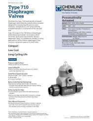
Instruction Manual<br />
<strong>CVS</strong> <strong>Type</strong> <strong>657</strong><br />
<strong>Diaphragm</strong> <strong>Actuator</strong><br />
Sizes 30-70<br />
All <strong>CVS</strong> <strong>Controls</strong> equipment, including actuators, are<br />
to be installed and maintained in accordance with<br />
instructions supplied by <strong>CVS</strong> <strong>Controls</strong>. Only<br />
qualified personnel may install and service the<br />
actuator, and, if necessary, contact a gas service<br />
person.<br />
Introduction<br />
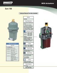
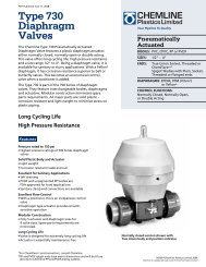
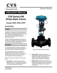
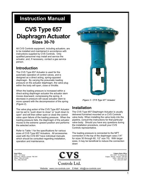
The <strong>CVS</strong> <strong>Type</strong> <strong>657</strong> <strong>Actuator</strong> is used for the<br />
automatic operation of control valves, and is<br />
designed as a direct acting, spring-opposed<br />
diaphragm. By varying the pneumatic loading<br />
pressure on the actuator diaphragm, the valve plug<br />
within the body will open, close or throttle.<br />
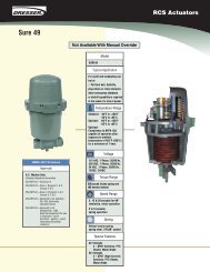
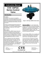
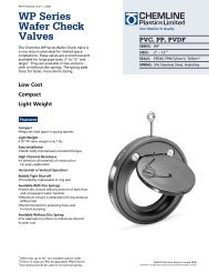
When the loading pressure is increased within a<br />
direct-acting diaphragm actuator the actuator stem<br />
moves downward, compressing the spring. A<br />
decrease in pressure will cause actuator stem to<br />
move upward with the decompression of the spring<br />
(Figure 2).<br />
The valve plug action of the <strong>CVS</strong> <strong>Type</strong> <strong>657</strong> <strong>Actuator</strong><br />
can be set to “push down to close” or “push down to<br />
open” and will then either open or close the control<br />
valve upon failure of the loading pressure. When the<br />
loading pressure fails, the diaphragm of the actuator<br />
moves to the extreme upward position and performs<br />
the selected action.<br />
Refer to Table 1 for the specifications for various<br />
sizes of <strong>CVS</strong> <strong>Type</strong> <strong>657</strong> <strong>Actuator</strong>s. All accessories<br />
used with the <strong>CVS</strong> <strong>657</strong> have individual manuals<br />
which should be consulted regarding installation,<br />
operation and maintenance.<br />
Figure 1: <strong>CVS</strong> <strong>Type</strong> <strong>657</strong> <strong>Actuator</strong><br />
Installation<br />
The <strong>CVS</strong> <strong>Type</strong> <strong>657</strong> <strong>Diaphragm</strong> <strong>Actuator</strong> is usually<br />
delivered furnished mounted on a <strong>CVS</strong> <strong>Controls</strong><br />
valve body. When installing the valve body into the<br />
pipeline, consult the instructions for that particular<br />
valve body. Should you have any questions during<br />
the installation procedure, consult your <strong>CVS</strong><br />
<strong>Controls</strong> representative.<br />
The loading pressure is connected to the NPT<br />
connection in the top of the diaphragm case (1/4”<br />
for sizes 30 through 60, 1/2” size 70). With larger<br />
sizes, it may be beneficial to reduce the connection<br />
down<br />
Head Office<br />
3900 – 101 Street<br />
Edmonton, Alberta, Canada T6E 0A5<br />
Office: (780) 437-3055<br />
Fax: (780) 436-5461<br />
Calgary Sales Office<br />
205, 2323 – 32 Avenue NE<br />
Calgary, Alberta, Canada T2E 6Z3<br />
Office: (403) 250-1416<br />
Fax: (403) 291-9487<br />
Website: www.cvs-controls.com<br />
E-Mail: info@cvs-controls.com<br />
1
Table 1: <strong>CVS</strong> <strong>Type</strong> <strong>657</strong> <strong>Diaphragm</strong> <strong>Actuator</strong><br />
<strong>Actuator</strong> Size 30 34 40 45 46 50 60 70<br />
Nominal Effective Area<br />
(Sq.In.) (<strong>Diaphragm</strong>)<br />
Yoke Boss Size Diameter<br />
(In.)<br />
46 69 69 105 156 105 156 220<br />
2-1/8 2-1/8 2-13/16 2-13/16 2-13/16 3-9/16 3-9/16 3-9/16<br />
Valve Body Stem Size (In.) 3/8 3/8 1/2 1/2 1/2 3/4 3/4 3/4<br />
Maximum Allowable Stem<br />
Force (Lbs)<br />
2300 2300 2700 5650 7550 5650 6800 8800<br />
Maximum Travel (In.) 3/4 1-1/8 1-1/2 2 2 2 2 3<br />
Maximum <strong>Diaphragm</strong> Case<br />
Pressure (PSI)*<br />
140 75 75 60 50 60 50 65<br />
Approximate Kg 16 22 23 37 49 42 53 107<br />
Weight Lb 36 48 51 82 107 92 116 235<br />
*Maximum allowable diaphragm case pressure may be used only when maximum allowable stem forces are not exceeded.<br />
Installation cont’d<br />
to 1/4”. Pipe or tubing may be used, and should be<br />
run to the output pressure connection on the<br />
automatic controller. Avoid transmission lag in the<br />
control signal by keeping the length of pipe or<br />
tubing as short as possible. When long distances<br />
are involved, install a valve positioner on the<br />
actuator. If the valve positioner is provided as part<br />
of the original equipment, the loading pressure<br />
connection will be made at the <strong>CVS</strong> <strong>Controls</strong><br />
manufacturing facility.<br />
If the <strong>CVS</strong> <strong>Type</strong> <strong>657</strong> <strong>Diaphragm</strong> <strong>Actuator</strong> is<br />
shipped alone for field mounting, it should be<br />
mounted onto the valve body and secured in place<br />
with the yoke locknut. Clamp the actuator stem<br />
and valve plug stem together using the stem<br />
connector to provide the proper valve travel. Refer<br />
to the “Assembly Instructions” section of this<br />
manual for complete instructions.<br />
For ease of service, ensure that the control valve is<br />
located for easy access and serviceability with<br />
room above for accessibility. Ensure that sufficient<br />
room is provided below should removal of the<br />
actuator and valve plug be necessary.<br />
Operation and Adjustment<br />
Refer to the nameplate on the yoke of the actuator<br />
for details on the specific construction and<br />
operating range. The requirements of your specific<br />
application will dictate the spring and diaphragm<br />
used in your <strong>CVS</strong> <strong>Type</strong> <strong>657</strong> <strong>Actuator</strong>. When in<br />
service, the actuator will create full travel of the<br />
valve plug when diaphragm pressure is applied<br />
according to the range indicated on the name<br />
plate. Generally, the diaphragm pressure range is<br />
3 to 15 PSI or 6 to 30 PSI, but other ranges may be<br />
used.<br />
Pressure within the valve body creates forces on<br />
the valve plug which directly affect the actual<br />
operating diaphragm pressure range. When<br />
pressure conditions in the valve body are different<br />
from those indicated in the factory settings, the<br />
valve may not stroke completely over the indicated<br />
range. To achieve correct travel for the diaphragm<br />
pressure range utilized, a simple spring adjustment<br />
is necessary. Note, however, that the actuator<br />
spring has a fixed pressure span and that<br />
adjustment of the spring compression simply shifts<br />
this span up or down to make the travel of the valve<br />
correspond with the diaphragm pressure range.<br />
<strong>Type</strong> <strong>657</strong> Direct Acting<br />
<strong>Diaphragm</strong> <strong>Actuator</strong><br />
AIR<br />
PUSHES<br />
DOWN<br />
SPRING<br />
LIFTS<br />
STEM MOVES UPWARD WITH<br />
LOSS OF OPERATING MEDIUM<br />
Figure 2: Schematic of <strong>CVS</strong> <strong>Type</strong> 667 <strong>Actuator</strong><br />
2
Operation and Adjustment cont’d<br />
The <strong>CVS</strong> <strong>Controls</strong> nameplate indicates a “bench<br />
set” pressure range in addition to a standard<br />
diaphragm pressure range. The “bench set”<br />
pressure range indicates the range required to<br />
completely stroke the valve with out any pressure<br />
in the valve body, for example as if the valve<br />
were being tested on the work bench. While In<br />
service, however, with the specified pressure<br />
drop applied across the valve, it should stroke<br />
over the standard diaphragm pressure range as<br />
indicated on the nameplate.<br />
Once the control valve has been installed and<br />
connected to the controller, it should be tested for<br />
correct travel, lack of friction and correct action<br />
(air-to-open or air-to-close) to match the<br />
controlling instrument. To ensure the most<br />
effective operation, the actuator stem and the<br />
valve plug stem must move freely when<br />
responding to the loading pressure change on<br />
the diaphragm.<br />
Disassembly Instructions<br />
Although the following instructions describe how<br />
the <strong>CVS</strong> <strong>Type</strong> <strong>657</strong> <strong>Diaphragm</strong> <strong>Actuator</strong> can be<br />
completely disassembled, when inspection or<br />
repairs are required, only disassemble those<br />
parts required to accomplish the job.<br />
Consult Figure 4, and proceed as follows for<br />
disassembly:<br />
1. Bypass the control valve and exhaust any<br />
actuator loading pressure to atmospheric.<br />
Disconnect the actuator supply line and any<br />
leakoff piping.<br />
2. Relieve all pressure from the spring by<br />
threading the spring adjuster (key 2) out of<br />
the yoke.<br />
3. To remove the valve body from the actuator,<br />
separate the stem connector (key 21) and<br />
remove the yoke locknut.<br />
4. Loosen the stem locknuts (keys 13 and 14),<br />
remove the two cap screws and separate the<br />
stem connector.<br />
5. Loosen the diaphragm case cap screws and<br />
nuts (keys 19 and 20) and remove the upper<br />
diaphragm case.<br />
6. Remove the molded diaphragm (key 6).<br />
7. Extract the diaphragm plate and actuator<br />
stem (keys 5 and 3) as an assembly. These<br />
parts can be further separated if required.<br />
8. Remove the actuator spring (key 1) and<br />
spring seat (key 4).<br />
9. If necessary, remove the lower half of the<br />
diaphragm case (key 8) by loosening the cap<br />
screws.<br />
10. Removing the spring adjuster will complete the<br />
disassembly.<br />
Assembly Instructions<br />
1. The <strong>CVS</strong> <strong>Type</strong> <strong>657</strong> <strong>Actuator</strong> can be assembled in<br />
the reverse order of the disassembly instructions.<br />
These additional steps below will assist with<br />
proper assembly and continued operation.<br />
2. Apply lubricant to the threads and spring seat<br />
bearing surface of the spring adjuster (See<br />
location marked “LP” on Figure 4).<br />
3. Ensure that the spring seats and the lower seat<br />
align properly and rest against the diaphragm<br />
plate.<br />
4. Use a criss-cross pattern to evenly tighten the<br />
nuts on the casing bolts.<br />
5. If the stem locknuts were removed during<br />
disassembly, install them onto the valve plug<br />
stem and place the travel indicator (key 12) with<br />
the cupped side downward.<br />
6. Secure the actuator onto the valve body using<br />
the yoke locknut.<br />
7. Assemble the stem connection as follows<br />
according to the required action:<br />
a. Mounted on Body with “Push Down to<br />
Close” Valve Plug<br />
i. When the body is assembled and the<br />
actuator is mounted, ensure the valve<br />
plug is in the closed position.<br />
ii. Once the locknuts are secured onto the<br />
stem, set the travel indicator disc onto<br />
the locknuts with the cupped portion<br />
facing downward.<br />
iii. Raise the valve plug off of the seat, with<br />
the travel specified on the nameplate, or,<br />
pressure the actuator until the stem<br />
moves down the specified valve travel.<br />
iv. Install the stem connector by clamping<br />
the actuator stem to the valve stem.<br />
v. Raise the indicator disc to the stem<br />
connector, using the locknuts to tighten<br />
in position.<br />
vi. Ensure that the desired total travel is<br />
available by cycling the actuator. This<br />
will also demonstrate that the valve plug<br />
seats properly. If necessary, minor travel<br />
adjustments can be made by slightly<br />
loosening the stem connector, tightening<br />
the locknuts and screwing the stem<br />
either into or out of the stem connector<br />
using a wrench on the locknuts.<br />
3
vii. Once the valve travel has been<br />
accomplished, secure the stem<br />
connector, lock the travel indicator<br />
disc against the connector using the<br />
locknuts, and adjust the travel<br />
indicator scale (key 16) to show<br />
valve plug position.<br />
viii. Using a gauge, measure the<br />
pressure delivered to the actuator.<br />
Make any adjustments on the<br />
actuator, or the positioner, to set the<br />
starting point of valve travel and<br />
ensure full range of travel as desired.<br />
b. Mounted on Body with “Push Down to<br />
Open” Valve Plug<br />
i. Attach the locknuts to the stem and<br />
set the travel indicator disc into<br />
position.<br />
ii. Raise the valve plug to the closed<br />
position. On larger body sizes, a pry<br />
bar may be inserted through the<br />
body line flange opening. If the valve<br />
is located in a pipeline application,<br />
you may remove the bottom flange<br />
and raise the valve plug from below.<br />
iii. Install the stem connector and<br />
ensure that the actuator stem<br />
threads are fully engaged.<br />
iv. Install the two cap screws in the<br />
stem connector to clamp the actuator<br />
stem to the valve stem.<br />
v. If a pry bar has been used, remove it<br />
now. If the bottom flange has been<br />
removed, replace it now.<br />
vi. Apply loading pressure to the<br />
diaphragm case and move the valve<br />
plug down off of its seat.<br />
vii. Rotate the valve plug stem into the<br />
stem connector approximately 1/8”.<br />
Slightly tighten the stem locknuts to<br />
move the travel indicator to the<br />
proper position.<br />
viii. Check the availability of desired<br />
travel by fully cycling the actuator.<br />
The valve plug should seat before<br />
the upper travel stop. If required,<br />
minor adjustments to total travel can<br />
be made by slightly loosening the<br />
stem connector, tightening the<br />
locknuts and screwing the stem<br />
either into or out of the stem<br />
connector using a wrench on the<br />
locknuts.<br />
ix.<br />
Note: When making adjustments to<br />
the valve stem, do not rotate the valve<br />
stem more than the 1/8” that it was<br />
screwed into the actuator stem in step<br />
“vii”. Over rotating the valve stem<br />
will prevent the valve from shutting<br />
off.<br />
Proceed with steps “vii” and “viii” as<br />
in section “A” above.<br />
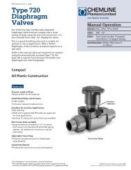
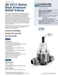
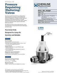
Serial Number<br />
Each <strong>CVS</strong> <strong>Type</strong> <strong>657</strong> <strong>Actuator</strong> has a serial<br />
number, stamped on the nameplate. When<br />
corresponding with your <strong>CVS</strong> <strong>Controls</strong><br />
representative, always refer to that serial number<br />
when requiring replacement parts or technical<br />
information.<br />
Figure 3: Nameplate on <strong>CVS</strong> <strong>Type</strong> 667 <strong>Actuator</strong><br />
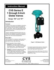
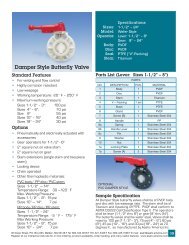
<strong>CVS</strong> <strong>Type</strong> <strong>657</strong> <strong>Actuator</strong> Parts List<br />
The following parts list includes complete part<br />
numbers for components of the <strong>CVS</strong> <strong>Type</strong> <strong>657</strong><br />
<strong>Actuator</strong> that are generally replaceable in the field,<br />
and are most commonly used. Key numbers<br />
correspond to those in Figure 4. If materials and<br />
parts are required, but are not outlined in this<br />
literature, consult your <strong>CVS</strong> <strong>Controls</strong><br />
representative. Include the serial number of your<br />
actuator in all correspondence regarding<br />
replacement parts.<br />
4
<strong>CVS</strong> <strong>Type</strong> <strong>657</strong> <strong>Actuator</strong><br />
Table 2: Parts Reference<br />
Key Part Name<br />
1 <strong>Actuator</strong> Spring<br />
2 Spring Adjuster<br />
3 <strong>Actuator</strong> Stem<br />
4 Spring Seat<br />
5 <strong>Diaphragm</strong> Plate<br />
6* <strong>Diaphragm</strong><br />
7 Upper <strong>Diaphragm</strong> Case<br />
8 Lower <strong>Diaphragm</strong> Case<br />
9 Yoke<br />
10 Cap Screw<br />
11 Cap Screw<br />
12 Travel Indicator<br />
13 Hex Nut<br />
14 Hex Jam Nut<br />
15 Self-Tapping Screw<br />
16 Travel Indicator Scale<br />
17 Nameplate<br />
18 Drive Screw<br />
19 Cap Screw<br />
20 Hex Nut<br />
21 Stem Connector<br />
22 Twin Speed Nut (not shown)<br />
23<br />
Pipe Bushing (Size 70 only)<br />
(not shown)<br />
* Recommended spare part<br />
Figure 4: <strong>CVS</strong> <strong>Type</strong> <strong>657</strong> <strong>Actuator</strong> Assembly Drawing<br />
Table 3: Parts List<br />
Key Description Part Number<br />
1 <strong>Actuator</strong> Spring Consult <strong>CVS</strong> <strong>Controls</strong><br />
Size 30<br />
<strong>CVS</strong>1E792924102<br />
2 Spring Adjustor<br />
Sizes 34, 40<br />
<strong>CVS</strong>1E807324102<br />
Sizes 45, 46, 50, 60<br />
<strong>CVS</strong>1E832624102<br />
Size 70<br />
<strong>CVS</strong>1N129724102<br />
Size 30<br />
<strong>CVS</strong>1E792824102<br />
Size 34<br />
<strong>CVS</strong>1E872924102<br />
3<br />
Size 40<br />
<strong>CVS</strong>1E807124102<br />
<strong>Actuator</strong> Stem<br />
Sizes 45, 46<br />
<strong>CVS</strong>1J332924102<br />
Steel, CD PL<br />
Sizes 50, 60<br />
<strong>CVS</strong>1E832424102<br />
Size 70<br />
Up to 2” Travel<br />
<strong>CVS</strong>1N129424102<br />
Over 2” Travel<br />
<strong>CVS</strong>1N132524102<br />
Size 30, Steel<br />
<strong>CVS</strong>1U425623122<br />
4 Lower Spring Seat<br />
Sizes 34,40, Steel<br />
<strong>CVS</strong>1R179923122<br />
Sizes 45, 46, 50, 60, Steel<br />
<strong>CVS</strong>1R180023122<br />
Size 70, Cast Iron<br />
<strong>CVS</strong>1N129619052<br />
Size 30<br />
<strong>CVS</strong>2E880419042<br />
5<br />
Sizes 34,40<br />
<strong>CVS</strong>3E880519042<br />
<strong>Diaphragm</strong> Plate<br />
Sizes 45, 50<br />
<strong>CVS</strong>2E831519042<br />
Cast Iron<br />
Sizes 46, 60<br />
<strong>CVS</strong>2E847519042<br />
Size 70<br />
<strong>CVS</strong>2N127019042<br />
5
<strong>CVS</strong> <strong>Type</strong> <strong>657</strong> <strong>Actuator</strong><br />
Parts List continued<br />
Key Description Part Number<br />
Size 30<br />
<strong>CVS</strong>2E791902202<br />
6<br />
Sizes 34, 40<br />
<strong>CVS</strong>2E670002202<br />
<strong>Diaphragm</strong><br />
Sizes 45, 50<br />
<strong>CVS</strong>2E859502202<br />
Nitrile<br />
Sizes 46, 50<br />
<strong>CVS</strong>2E859702202<br />
Size 70<br />
<strong>CVS</strong>2N126902202<br />
Size 30<br />
<strong>CVS</strong>2E791528992<br />
Upper <strong>Diaphragm</strong> Sizes 34, 40<br />
<strong>CVS</strong>2E806028992<br />
7 Casing<br />
Sizes 45, 50<br />
<strong>CVS</strong>3E830928992<br />
Steel<br />
Sizes 46, 60<br />
<strong>CVS</strong>2E847228992<br />
Size 70<br />
<strong>CVS</strong>2N126628992<br />
Size 30<br />
<strong>CVS</strong>2E792225062<br />
Lower <strong>Diaphragm</strong> Sizes 34, 40<br />
<strong>CVS</strong>2E806325062<br />
8 Casing<br />
Sizes 45, 50<br />
<strong>CVS</strong>3E831625062<br />
Steel<br />
Sizes 46, 60<br />
<strong>CVS</strong>2E847425062<br />
Size 70<br />
<strong>CVS</strong>2N127125062<br />
Size 30<br />
<strong>CVS</strong>3E792619042<br />
Size 34<br />
<strong>CVS</strong>2E869619042<br />
9<br />
Yoke<br />
Size 40<br />
<strong>CVS</strong>3E807019042<br />
Cast Iron<br />
Sizes 45, 46<br />
<strong>CVS</strong>2E903719042<br />
Sizes 50, 60<br />
<strong>CVS</strong>3E832319042<br />
Size 70<br />
<strong>CVS</strong>3N127319042<br />
10<br />
Size 30<br />
<strong>CVS</strong>1E798032982<br />
Cap Screw<br />
Sizes 34, 40<br />
<strong>CVS</strong>1E760432992<br />
Steel, CD PL<br />
Sizes 45, 46, 50, 60, 70<br />
<strong>CVS</strong>1E775432982<br />
Size 30 (6 req’d)<br />
<strong>CVS</strong>1D529824052<br />
Push Down to Sizes 34, 40 (6 req’d)<br />
<strong>CVS</strong>1A368424052<br />
Close Valve Sizes 45, 46, 50, 60 (8 req’d) <strong>CVS</strong>1A368424052<br />
11 Cap Screw<br />
Size 70<br />
<strong>CVS</strong>1N129328992<br />
Size 30 (3 req’d)<br />
<strong>CVS</strong>1D368424052<br />
Push Down to Sizes 34, 40 (3 req’d)<br />
<strong>CVS</strong>1A368424052<br />
Open Valve Sizes 45, 46, 50, 70 (4 req’d) <strong>CVS</strong>1A368424052<br />
Size 70 (9 req’d)<br />
<strong>CVS</strong>1N129328992<br />
Sizes 30, 34<br />
<strong>CVS</strong>1E793138992<br />
12 Travel Indicator, SST Sizes 40, 45, 46<br />
<strong>CVS</strong>1E807238992<br />
Sizes 50, 60, 70<br />
<strong>CVS</strong>1B832838992<br />
Sizes 30, 34 (2 req’d)<br />
<strong>CVS</strong>1P131224142<br />
13 Hex Nut, SST Size 40, 46<br />
<strong>CVS</strong>1A413224122<br />
Sizes 50, 60, 70<br />
<strong>CVS</strong>1A375424122<br />
Size 40<br />
<strong>CVS</strong>1A353724122<br />
14 Hex Jam Nut, SST Sizes 45, 46 (2 req’d)<br />
<strong>CVS</strong>1A353724122<br />
Sizes 50, 60, 70<br />
<strong>CVS</strong>1A351124122<br />
15<br />
Self-tapping Screw, Sizes 30, 34, 45, 46 (2 req’d)<br />
<strong>CVS</strong>11793238992<br />
SST Sizes 50, 60, 70 (2 req’d) <strong>CVS</strong>1E831338992<br />
16 Travel Indicator Scale, SST See following Table 4<br />
17 Nameplate, SST <strong>CVS</strong>12B6508X0A2<br />
18 Drive Screw, SST (4 req’d) <strong>CVS</strong>1A368228982<br />
19<br />
Cap Screw, Standard Size 30, 34, 40, 45, 50, 60<br />
1” bolt<br />
3/8” Bolt Size 70 1-1/4” bolt<br />
20 Hex Nut, Standard 3/8” Nut 1” Nut<br />
Sizes 30, 34<br />
<strong>CVS</strong>1E7977000A2<br />
Size 40<br />
<strong>CVS</strong>1F659225142<br />
21 Stem Connector, STL Sizes 45, 46<br />
<strong>CVS</strong>1J3330000A2<br />
Sizes 50, 60<br />
<strong>CVS</strong>1E8337000A2<br />
Size 70<br />
<strong>CVS</strong>1H8655000A2<br />
Sizes 30, 34<br />
<strong>CVS</strong>1E793938992<br />
22 Twin Speed Nut, SST Sizes 40, 45, 46<br />
<strong>CVS</strong>1E808438992<br />
Sizes 50, 60, 70<br />
<strong>CVS</strong>1E833538992<br />
23<br />
Pipe Bushing,<br />
Steel, PL<br />
Size 70<br />
<strong>CVS</strong>1C379026232<br />
6
Table 4: Travel Indicator Scale<br />
<strong>Actuator</strong> Size<br />
Part Numbers<br />
3/4” Travel 1-1/8” Travel 1’1/2” Travel 2” Travel 3” Travel<br />
30, 34 <strong>CVS</strong>1E793638992<br />
40, 45, 46 <strong>CVS</strong>1E808138992 <strong>CVS</strong>1E808228992 <strong>CVS</strong>1E808338992 <strong>CVS</strong>1R444538982<br />
50, 60 <strong>CVS</strong>1E833138992 <strong>CVS</strong>1E833128992 <strong>CVS</strong>1E833338992 <strong>CVS</strong>1E833428992<br />
70 <strong>CVS</strong>1E833138992 <strong>CVS</strong>1E833238992 <strong>CVS</strong>1E833338992 <strong>CVS</strong>1E833438992 1N129838992<br />
Table 5: Thrust Capabilities by Input Signal Range<br />
Travel<br />
<strong>Actuator</strong><br />
Size<br />
Pressure<br />
Range to<br />
<strong>Actuator</strong><br />
<strong>Diaphragm</strong><br />
Bar<br />
Thrust<br />
Capabilities<br />
mm<br />
N<br />
19<br />
30<br />
0.2-1 2250<br />
0.4-2 3890<br />
34<br />
0.2-1 3380<br />
0.4-2 5830<br />
40<br />
0.2-1 3380<br />
0.4-2 5530<br />
29 45<br />
0.2-1 4670<br />
0.4-2 8410<br />
46<br />
0.2-1 6940<br />
0.4-2 13,190<br />
38<br />
50<br />
0.2-1 5140<br />
0.4-2 8410<br />
60<br />
0.2-1 6940<br />
0.4-2 13,190<br />
51 70<br />
0.2-1 7930<br />
0.4-2 18,590<br />
Inch Psig Lb<br />
3-15 506<br />
3/4<br />
1-1/8<br />
1-1/2<br />
30<br />
34<br />
40<br />
45<br />
46<br />
50<br />
60<br />
2 70<br />
6-30 874<br />
3-15 759<br />
6-30 1311<br />
3-15 759<br />
6-30 1242<br />
3-15 1050<br />
6-30 1890<br />
3-15 1560<br />
6-30 2964<br />
3-15 1155<br />
6-30 1890<br />
3-15 1560<br />
6-30 2964<br />
3-15 1760<br />
6-30 4180<br />
7
Head Office<br />
3900 – 101 Street<br />
Edmonton, Alberta, Canada T6E 0A5<br />
Office: (780) 437-3055<br />
Fax: (780) 436-5461<br />
Calgary Sales Office<br />
205, 2323 – 32 Avenue NE<br />
Calgary, Alberta, Canada T2E 6Z3<br />
Office: (403) 250-1416<br />
Fax: (403) 291-9487<br />
Website: www.cvs-controls.com<br />
E-Mail: info@cvs-controls.com<br />
Rev 2 12/05<br />
Printed in Canada<br />
8