Siemens Oxymat 6
Siemens Oxymat 6
Siemens Oxymat 6

You also want an ePaper? Increase the reach of your titles
YUMPU automatically turns print PDFs into web optimized ePapers that Google loves.
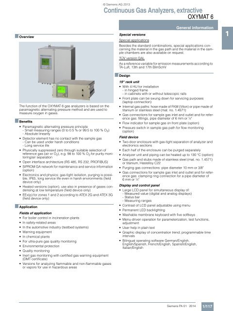
■ Overview<br />
© <strong>Siemens</strong> AG 2013<br />
Continuous Gas Analyzers, extractive<br />
OXYMAT 6<br />
General information<br />
Special versions<br />
Special applications<br />
Besides the standard combinations, special applications concerning<br />
the material in the gas path and the material in the sample<br />
chambers are also available on request.<br />
TÜV version QAL<br />
As a reference variable for emission measurements according to<br />
TA-Luft, 13th and 17th BlmSchV<br />
1<br />
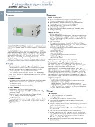
The function of the OXYMAT 6 gas analyzers is based on the<br />
paramagnetic alternating pressure method and are used to<br />
measure oxygen in gases.<br />
■ Benefits<br />
• Paramagnetic alternating pressure principle<br />
- Small measuring ranges (0 to 0.5 % or 99.5 to 100 % O 2 )<br />
- Absolute linearity<br />
• Detector element has no contact with the sample gas<br />
- Can be used under harsh conditions<br />
- Long service life<br />
• Physically suppressed zero through suitable selection of<br />
reference gas (air or O 2 ), e.g. 98 to 100 % O 2 for purity monitoring/air<br />
separation<br />
• Open interface architecture (RS 485, RS 232, PROFIBUS)<br />
• SIPROM GA network for maintenance and service information<br />
(option)<br />
• Electronics and physics: gas-tight isolation, purging is possible,<br />
IP65, long service life even in harsh environments (field<br />
device only)<br />
• Heated versions (option), use also in presence of gases condensing<br />
at low temperature (field device only)<br />
• EEx(p) for zones 1 and 2 according to ATEX 2G and ATEX 3G<br />
(field device only)<br />
■ Application<br />
Fields of application<br />
• For boiler control in incineration plants<br />
• In safety-related areas<br />
• In the automotive industry (testbed systems)<br />
• Warning equipment<br />
• In chemical plants<br />
• For ultra-pure gas quality monitoring<br />
• Environmental protection<br />
• Quality monitoring<br />
• Inert gas monitoring with certified gas warning equipment<br />
(DMT certificate)<br />
• Versions for analyzing flammable and non-flammable gases<br />
or vapors for use in hazardous areas<br />
■ Design<br />
19" rack unit<br />
• With 4 HU for installation<br />
- in hinged frame<br />
- in cabinets with or without telescopic rails<br />
• Front plate can be swung down for servicing purposes<br />
(laptop connection)<br />
• Internal gas paths: hose made of FKM (Viton) or pipe made of<br />
titanium or stainless steel (mat. no. 1.4571)<br />
• Gas connections for sample gas inlet and outlet and for reference<br />
gas: fittings, pipe diameter of 6 mm or ¼"<br />
• Flow indicator for sample gas on front plate (option)<br />
• Pressure switch in sample gas path for flow monitoring<br />
(option)<br />
Field device<br />
• Two-door enclosure with gas-tight separation of analyzer and<br />
electronics sections<br />
• Each half of the enclosure can be purged separately<br />
• Analyzer unit and piping can be heated up to 130 °C (option)<br />
• Gas path and stubs made of stainless steel (mat. no. 1.4571)<br />
or titanium, Hastelloy C22<br />
• Purging gas connections: pipe diameter 10 mm or 3/8"<br />
• Gas connections for sample gas inlet and outlet and for reference<br />
gas: clamping ring connection for a pipe diameter of<br />
6 mm or ¼"<br />
Display and control panel<br />
• Large LCD panel for simultaneous display of:<br />
- Measured value (digital and analog displays)<br />
-Status bar<br />
- Measuring ranges<br />
• Contrast of LCD panel adjustable using menu<br />
• Permanent LED backlighting<br />
• Washable membrane keyboard with five softkeys<br />
• Menu-driven operation for parameterization, test functions,<br />
adjustment<br />
• User help in plain text<br />
• Graphic display of concentration trend; programmable time<br />
intervals<br />
• Bilingual operating software German/English,<br />
English/Spanish, French/English, Spanish/English,<br />
Italian/English<br />
<strong>Siemens</strong> PA 01 · 2014<br />
1/117
© <strong>Siemens</strong> AG 2013<br />
Continuous Gas Analyzers, extractive<br />
OXYMAT 6<br />
General information<br />
1 Input and outputs<br />
• One analog output per measured component (from 0, 2, 4 to<br />
20 mA; NAMUR parameterizable)<br />
• Two analog inputs configurable (e.g. correction of cross-interference,<br />
external pressure sensor)<br />
• Six binary inputs freely configurable (e.g. for measurement<br />
range switchover, processing of external signals from sample<br />
preparation)<br />
• Six relay outputs freely configurable (failure, maintenance request,<br />
maintenance switch, threshold alarm, external magnetic<br />
valves)<br />
• Expansion: by eight additional binary inputs and eight additional<br />
relay outputs each, e.g. for autocalibration with up to<br />
four calibration gases<br />
Communication<br />
RS 485 present in the basic unit (connection at the rear; for the<br />
rack unit also behind the front plate).<br />
Options<br />
• AK interface for the automotive industry with extended functions<br />
• RS 485/RS 232 converter<br />
• RS 485/Ethernet converter<br />
• RS 485/USB converter<br />
• Connection to networks via PROFIBUS DP/PA interface<br />
• SIPROM GA software as the service and maintenance tool<br />
LED backlit graphic<br />
display and<br />
membrane keyboard<br />
with noticeable click<br />
Status line for display<br />
of analyzer status<br />
(programmable)<br />
Two code levels<br />
according to NAMUR<br />
(maintenance and<br />
specialist level)<br />
Easy operation with<br />
menu control<br />
using five softkeys<br />
Display of<br />
concentrations as<br />
numbers and bargraph<br />
Display of<br />
start-of-scale and<br />
full-scale values<br />
Display of current<br />
measuring ranges<br />
Keyboard to<br />
enter values<br />
ESC key<br />
to abort inputs<br />
INFO key<br />
for help in plain text<br />
CLEAR key<br />
to delete inputs<br />
ENTER key<br />
to accept<br />
input values<br />
MEAS key<br />
to return to<br />
measurement mode<br />
OXYMAT 6, membrane keyboard and graphic display<br />
1/118 <strong>Siemens</strong> PA 01 · 2014
© <strong>Siemens</strong> AG 2013<br />
Continuous Gas Analyzers, extractive<br />
OXYMAT 6<br />
Designs – Parts touched by sample gas, standard<br />
General information<br />
Gas path 19" rack unit Field device Field device Ex<br />
With hoses<br />
Bushing<br />
Stainless steel, mat. no. - -<br />
1.4571<br />
With pipes<br />
With pipes<br />
With pipes<br />
Hose<br />
Sample chamber<br />
Fittings for sample chamber<br />
Restrictor<br />
O-rings<br />
Bushing<br />
Pipe<br />
Sample chamber<br />
Restrictor<br />
O-rings<br />
Bushing<br />
Pipe<br />
Sample chamber<br />
Restrictor<br />
O-rings<br />
Bushing<br />
Pipe<br />
Sample chamber<br />
Restrictor<br />
O-rings<br />
FKM (e.g. Viton)<br />
Stainless steel, mat. no.<br />
1.4571 or Tantalum<br />
Stainless steel, mat. no.<br />
1.4571<br />
PTFE (e.g. Teflon)<br />
FKM (e.g. Viton)<br />
Titanium<br />
Titanium<br />
Stainless steel, mat. no. 1.4571 or Tantalum<br />
Titanium<br />
FKM (Viton) or FFKM (Kalrez)<br />
Stainless steel, mat. no. 1.4571<br />
Stainless steel, mat. no. 1.4571<br />
Stainless steel, mat. no. 1.4571 or tantalum<br />
Stainless steel, mat. no. 1.4571<br />
FKM (Viton) or FFKM (Kalrez)<br />
Hastelloy C 22<br />
Hastelloy C 22<br />
Stainless steel, mat. no. 1.4571 or tantalum<br />
Hastelloy C 22<br />
FKM (e.g. Viton) or FFKM (e.g. Kalrez)<br />
1<br />
Options<br />
Flow indicator<br />
Measurement pipe<br />
Variable area<br />
Suspension boundary<br />
Duran glass<br />
Duran glass, black<br />
PTFE (Teflon)<br />
- -<br />
Angle pieces<br />
FKM (Viton)<br />
Pressure switch<br />
Membrane<br />
Enclosure<br />
FKM (Viton)<br />
PA 6.3 T<br />
- -<br />
<strong>Siemens</strong> PA 01 · 2014<br />
1/119
© <strong>Siemens</strong> AG 2013<br />
Continuous Gas Analyzers, extractive<br />
OXYMAT 6<br />
General information<br />
1 Gas path (19" rack unit)<br />
Legend for the gas path figures<br />
1 Sample gas inlet 8 Pressure switch in sample gas path (option)<br />
2 Sample gas outlet 9 Purging gas<br />
3 Not used 10 Pressure switch in reference gas path (option)<br />
4 Reference gas inlet 11 Pressure sensor<br />
5 Restrictor in reference gas inlet 12 Filter<br />
6 O 2 physical system 13 Flow indicator in sample gas path (option)<br />
7 Restrictor in sample gas path 14 Outlet restrictor<br />
<br />
<br />
<br />
<br />
<br />
<br />
<br />
<br />
<br />
<br />
<br />
<br />
<br />
<br />
Gas path, reference gas connection 1 100 hPa, absolute<br />
F<br />
13<br />
7<br />
6<br />
P<br />
8<br />
1<br />
2<br />
P<br />
11<br />
5<br />
P<br />
12<br />
4<br />
10<br />
9<br />
Gas path, reference gas connection 3 000 to 5 000 hPa, absolute<br />
1/120 <strong>Siemens</strong> PA 01 · 2014
© <strong>Siemens</strong> AG 2013<br />
Continuous Gas Analyzers, extractive<br />
OXYMAT 6<br />
Gas path (field device)<br />
Legend for the gas path figures<br />
1 Not used 8 Purging gas inlet (analyzer side)<br />
2 Sample gas inlet 9 Pressure sensor<br />
3 Reference gas inlet 10 O 2 physical system<br />
4 Sample gas outlet 11 Restrictor in sample gas path<br />
5 Purging gas inlet (electronics side) 12 Pressure sensor in reference gas path (option)<br />
6 Purging gas outlet (electronics side) 13 Restrictor<br />
7 Purging gas outlet (analyzer side) 14 Outlet restrictor<br />
General information<br />
1<br />
<br />
<br />
<br />
<br />
<br />
<br />
<br />
<br />
<br />
<br />
<br />
Gas path, reference gas connection 1 100 hPa, absolute<br />
<br />
<br />
<br />
<br />
<br />
<br />
<br />
<br />
<br />
<br />
<br />
Gas path, reference gas connection 3 000 to 5 000 hPa, absolute<br />
<strong>Siemens</strong> PA 01 · 2014<br />
1/121
© <strong>Siemens</strong> AG 2013<br />
Continuous Gas Analyzers, extractive<br />
OXYMAT 6<br />
1 ■ Function<br />
General information<br />
Principle of operation<br />
In contrast to almost all other gases, oxygen is paramagnetic.<br />
This property is utilized as the measuring principle by the<br />
OXYMAT 6 gas analyzers.<br />
Oxygen molecules in an inhomogeneous magnetic field are<br />
drawn in the direction of increased field strength due to their<br />
paramagnetism. When two gases with different oxygen contents<br />
meet in a magnetic field, a pressure difference is produced between<br />
them.<br />
<br />
<br />
<br />
In the case of OXYMAT 6, one gas (1) is a reference gas (N 2 , O 2<br />
or air), the other is the sample gas (5). The reference gas is introduced<br />
into the sample chamber (6) through two channels (3).<br />
One of these reference gas streams meets the sample gas within<br />
the area of a magnetic field (7). Because the two channels are<br />
connected, the pressure, which is proportional to the oxygen<br />
content, causes a cross flow. This flow is converted into an electric<br />
signal by a microflow sensor (4).<br />
The microflow sensor consists of two nickel-plated grids heated<br />
to approximately 120 ºC, which, along with two supplementary<br />
resistors, form a Wheatstone bridge. The pulsating flow results<br />
in a change in the resistance of the Ni grids. This leads to an offset<br />
in the bridge which is dependent on the oxygen concentration<br />
of the sample gas.<br />
Because the microflow sensor is located in the reference gas<br />
stream, the measurement is not influenced by the thermal conductivity,<br />
the specific heat or the internal friction of the sample<br />
gas. This also provides a high degree of corrosion resistance<br />
because the microflow sensor is not exposed to the direct influence<br />
of the sample gas.<br />
By using a magnetic field with alternating strength (8), the effect<br />
of the background flow in the microflow sensor is not detected,<br />
and the measurement is thus independent of the instrument’s<br />
operating position.<br />
The sample chamber is directly in the sample path and has a<br />
small volume, and the microflow sensor is a low-lag sensor. This<br />
results in a very short response time for the OXYMAT 6.<br />
Vibrations frequently occur at the place of installation and may<br />
falsify the measured signal (noise). A further microflow sensor<br />
(10) through which no gas passes acts as a vibration sensor. Its<br />
signal is applied to the measured signal as compensation.<br />
If the density of the sample gas deviates by more than 50 % from<br />
that of the reference gas, the compensation microflow sensor<br />
(10) is flushed with reference gas just like the measuring sensor<br />
(4).<br />
Note<br />
The sample gases must be fed into the analyzers free of dust.<br />
Condensation should be prevented from occurring in the sample<br />
chambers. Therefore, the use of gas modified for the measuring<br />
task is necessary in most application cases.<br />
<br />
<br />
<br />
<br />
D<br />
<br />
<br />
<br />
<br />
<br />
<br />
<br />
<br />
1 Reference gas inlet<br />
2 Restrictors<br />
3 Reference gas channels<br />
4 Microflow sensor for measurement<br />
5 Sample gas inlet<br />
6 Sample cell<br />
7 Paramagnetic effect<br />
8 Electromagnet with alternating field strength<br />
9 Sample gas and reference gas outlet<br />
10 Microflow sensor in compensation system<br />
(without flow)<br />
<br />
<br />
<br />
OXYMAT 6, principle of operation<br />
1/122 <strong>Siemens</strong> PA 01 · 2014
© <strong>Siemens</strong> AG 2013<br />
Continuous Gas Analyzers, extractive<br />
OXYMAT 6<br />
Advantages of the function-based application of reference<br />
gas<br />
• The zero point can be defined specific to the application. It is<br />
then also possible to set "physically" suppressed zero points.<br />
For example, it is possible when using pure oxygen as the<br />
zero gas to set a measuring range of 99.5 to 100 % O 2 with a<br />
resolution of 50 ppm.<br />
• The sensor (microflow sensor) is located outside the sample<br />
gas. Through use of an appropriate material in the gas path<br />
this also allows measurements in highly corrosive gases.<br />
• Pressure variations in the sample gas can be compensated<br />
better since the reference gas is subjected to the same fluctuations.<br />
• No influences on the thermal conductivity of the sample gas<br />
since the sensor is positioned on the reference gas side.<br />
• The same gas is used for the serial gas calibration and as the<br />
reference gas. As a result of the low consumption of reference<br />
gas (3 to 10 ml/min), one calibration cylinder can be used for<br />
both gases.<br />
• No measuring effect is generated in the absence of oxygen.<br />
The measured signal need not therefore be set electronically<br />
to zero, and is thus extremely stable with regard to temperature<br />
and electronic influences.<br />
General information<br />
Essential characteristics<br />
• Four freely parameterizable measuring ranges, also with suppressed<br />
zero point, all measuring ranges linear<br />
• Measuring ranges with physically suppressed zero point possible<br />
• Measuring range identification<br />
• Galvanically isolated measured-value output 0/2/4 to 20 mA<br />
(also inverted)<br />
• Autoranging possible; remote switching is also possible<br />
• Storage of measured values possible during adjustments<br />
• Wide range of selectable time constants (static/dynamic noise<br />
suppression); i.e. the response time of the analyzer can be<br />
matched to the respective measuring task<br />
• Short response time<br />
• Low long-term drift<br />
• Measuring point switchover for up to 6 measuring points<br />
(programmable)<br />
• Measuring point identification<br />
• Internal pressure sensor for correction of pressure variations<br />
in sample gas range 500 to 2 000 hPa (abs.)<br />
• External pressure sensor - only with piping as the gas path -<br />
can be connected for correction of variations in the sample<br />
gas pressure up to 3 000 hPa absolute (option)<br />
• Monitoring of sample gas flow (option for version with hoses)<br />
• Monitoring of sample gas and/or reference gas (option)<br />
• Monitoring of reference gas with reference gas connection<br />
3 000 to 5 000 hPa (abs.) (option)<br />
• Automatic, parameterizable measuring range calibration<br />
• Operation based on the NAMUR recommendation<br />
• Two control levels with their own authorization codes for the<br />
prevention of accidental and unauthorized operator interventions<br />
• Simple handling using a numerical membrane keyboard and<br />
operator prompting<br />
• Customer-specific analyzer options such as:<br />
- Customer acceptance<br />
-TAG labels<br />
- Drift recording<br />
- Clean for O 2 service<br />
- Kalrez gaskets<br />
• Analyzer unit with flow-type compensation branch: a flow is<br />
passed through the compensation branch (option) to reduce<br />
the vibration dependency in the case of highly different densities<br />
of the sample and reference gases<br />
• Sample chamber for use in presence of highly corrosive sample<br />
gases<br />
1<br />
<strong>Siemens</strong> PA 01 · 2014<br />
1/123
© <strong>Siemens</strong> AG 2013<br />
Continuous Gas Analyzers, extractive<br />
OXYMAT 6<br />
General information<br />
1 Reference gases<br />
Measuring range Recommended reference gas Reference gas connection<br />
pressure<br />
0 to ... vol.% O 2 N 2 2 000 … 4 000 hPa above sample<br />
gas pressure (max. 5 000 hPa<br />
... to 100 vol.% O 2 (suppressed O 2<br />
absolute)<br />
zero point with full-scale value<br />
100 vol.% O 2 )<br />
Around 21 vol.% O 2 (suppressed Air<br />
100 hPa with respect to sample gas<br />
zero point with 21 vol.% O 2 within<br />
pressure which may vary by max.<br />
the measuring span)<br />
50 hPa around the atmospheric<br />
pressure<br />
Table 1: Reference gases for OXYMAT 6<br />
Correction of zero point error / cross-sensitivities<br />
Accompanying gas<br />
(concentration 100 vol. %)<br />
Organic gases<br />
Deviation from zero point in<br />
vol. % O 2 absolute<br />
Table 2: Zero point error due to diamagnetism or paramagnetism of some accompanying gases with reference to nitrogen at 60 °C und 1 000 hPa<br />
absolute (according to IEC 1207/3)<br />
Conversion to other temperatures:<br />
The deviations from the zero point listed in Table 2 must be multiplied by a correction factor (k):<br />
• with diamagnetic gases: k = 333 K / ( [°C] + 273 K)<br />
• with paramagnetic gases: k = [333 K / ( [°C] + 273 K)] 2<br />
(all diamagnetic gases have a negative deviation from zero point)<br />
Accompanying gas<br />
(concentration 100 vol. %)<br />
Inert gases<br />
Remarks<br />
Ethane C 2 H 6 -0.49 Helium He +0.33<br />
Ethene (ethylene) C 2 H 4 -0.22 Neon Ne +0.17<br />
Ethine (acetylene) C 2 H 2 -0.29 Argon Ar -0.25<br />
1.2 butadiene C 4 H 6 -0.65 Krypton Kr -0.55<br />
1.3 butadiene C 4 H 6 -0.49 Xenon Xe -1.05<br />
n-butane C 4 H 10 -1.26<br />
iso-butane C 4 H 10 -1.30 Inorganic gases<br />
1-butene C 4 H 8 -0.96 Ammonia NH 3 -0.20<br />
iso-butene C 4 H 8 -1.06 Hydrogen bromide HBr -0.76<br />
Dichlorodifluoromethane (R12) CCl 2 F 2 -1.32 Chlorine Cl 2 -0.94<br />
Acetic acid CH 3 COOH -0.64 Hydrogen chloride HCl -0.35<br />
n-heptane C 7 H 16 -2.40 Dinitrogen monoxide N 2 O -0.23<br />
n-hexane C 6 H 14 -2.02 Hydrogen fluoride HF +0.10<br />
Cyclo-hexane C 6 H 12 -1.84 Hydrogen iodide HI -1.19<br />
Methane CH 4 -0.18 Carbon dioxide CO 2 -0.30<br />
Methanol CH 3 OH -0.31 Carbon monoxide CO +0.07<br />
n-octane C 8 H 18 -2.78 Nitrogen oxide NO +42.94<br />
n-pentane C 5 H 12 -1.68 Nitrogen N 2 0.00<br />
iso-pentane C 5 H 12 -1.49 Nitrogen dioxide NO 2 +20.00<br />
Propane C 3 H 8 -0.87 Sulfur dioxide SO 2 -0.20<br />
Propylene C 3 H 6 -0.64 Sulfur hexafluoride SF 6 -1.05<br />
Trichlorofluoromethane (R11) CCl 3 F -1.63 Hydrogen sulfide H 2 S -0.44<br />
Vinyl chloride C 2 H 3 Cl -0.77 Water H 2 O -0.03<br />
Vinyl fluoride C 2 H 3 F -0.55 Hydrogen H 2 +0.26<br />
1.1 vinylidene chloride C 2 H 2 Cl 2 -1.22<br />
The reference gas flow is set automatically<br />
to 5 … 10 ml/min (up to<br />
20 ml/min with flow-type compensation<br />
branch)<br />
Deviation from zero point in<br />
vol. % O 2 absolute<br />
1/124 <strong>Siemens</strong> PA 01 · 2014
© <strong>Siemens</strong> AG 2013<br />
Continuous Gas Analyzers, extractive<br />
OXYMAT 6<br />
■ Technical specifications<br />
General information<br />
Measuring ranges<br />
Smallest possible span (relating to<br />
sample gas pressure 1 000 hPa<br />
absolute, 0.5 l/min sample gas flow<br />
and 25 °C ambient temperature)<br />
Largest possible measuring span<br />
Measuring ranges with suppressed<br />
zero point<br />
Operating position<br />
Conformity<br />
4, internally and externally switchable;<br />
autoranging is also possible<br />
0.5 vol.%, 2 vol.% or 5 vol.% O 2<br />
100 vol.% O 2 (for a pressure<br />
above 2 000 hPa: 25 vol.% O 2 )<br />
Any zero point can be implemented<br />
within 0 … 100 vol.%,<br />
provided that a suitable reference<br />
gas is used (see Table 1 in<br />
"Function")<br />
Front wall, vertical<br />
CE mark in accordance with<br />
EN 50081-1, EN 50082-2<br />
Design, enclosure<br />
Degree of protection IP20 according to EN 60529<br />
Weight<br />
Approx. 13 kg<br />
Electrical characteristics<br />
Power supply<br />
100 … 120 V AC (nominal range<br />
of use 90 … 132 V), 48 … 63 Hz<br />
or 200 … 240 V AC (nominal<br />
range of use 180 … 264 V),<br />
48 … 63 Hz<br />
Power consumption<br />
Approx. 35 VA<br />
EMC<br />
(Electromagnetic Compatibility)<br />
In accordance with standard<br />
requirements of NAMUR NE21<br />
(08/98), EN 61326, EN 50270<br />
(with gas warning unit)<br />
Electrical safety According to EN 61010-1,<br />
overvoltage category III<br />
Fuse values 100 ... 120 V: 1.0 T/250<br />
200 ... 240 V: 0.63 T/250<br />
Gas inlet conditions<br />
Permissible sample gas pressure<br />
• With pipes<br />
500 … 3 000 hPa absolute<br />
• With hoses<br />
- Without pressure switch 500 … 1 500 hPa absolute<br />
- With pressure switch 500 … 1 300 hPa absolute<br />
Sample gas flow<br />
18 … 60 l/h (0.3 … 1 l/min)<br />
Sample gas temperature<br />
Min. 0 ... max. 50 °C, but above<br />
the dew point<br />
Sample gas humidity<br />
< 90 % RH (RH: relative humidity)<br />
Reference gas pressure<br />
(high-pressure version)<br />
Reference gas pressure<br />
(low-pressure version)<br />
2 000 ... 4 000 hPa above sample<br />
gas pressure, but max. 5 000 hPa<br />
Min. 100 hPa above sample gas<br />
pressure<br />
Dynamic response<br />
Warm-up period<br />
Delayed display (T 90 -time)<br />
Damping (electrical time constant)<br />
Dead time (purging time of the gas<br />
path in the unit at 1 l/min)<br />
Time for device-internal signal<br />
processing<br />
Pressure correction range<br />
Pressure sensor<br />
• Internal<br />
• External<br />
19" rack unit<br />
At room temperature < 30 min<br />
(the technical specification will be<br />
met after 2 hours)<br />
Min. 1.5 … 3.5 s, depending on<br />
version<br />
0 … 100 s, parameterizable<br />
Approximately 0.5 ... 2.5 s,<br />
depending on version<br />
© <strong>Siemens</strong> AG 2013<br />
Continuous Gas Analyzers, extractive<br />
OXYMAT 6<br />
19" rack unit<br />
1 Electrical inputs and outputs<br />
Analog output<br />
Relay outputs<br />
Analog inputs<br />
Binary inputs<br />
0/2/4 … 20 mA, isolated;<br />
max. load 750 <br />
6, with changeover contacts,<br />
freely parameterizable, e.g. for<br />
measuring range identification;<br />
load: 24 V AC/DC/1 A, isolated<br />
2, dimensioned for 0/2/4 ... 20 mA<br />
for external pressure sensor and<br />
residual gas influence correction<br />
(correction of cross-interference)<br />
6, designed for 24 V, isolated,<br />
freely parameterizable, e.g. for<br />
measuring range switchover<br />
Serial interface RS 485<br />
Options<br />
AUTOCAL function with 8 additional<br />
binary inputs and relay outputs<br />
each, also with PROFIBUS<br />
PA or PROFIBUS DP<br />
Climatic conditions<br />
Permissible ambient temperature -30 … +70 °C during storage and<br />
transportation, 5 … 45 °C during<br />
operation<br />
Permissible humidity<br />
< 90 % RH (RH: relative humidity)<br />
within average annual value, during<br />
storage and transportation<br />
(dew point must not be undershot)<br />
1/126 <strong>Siemens</strong> PA 01 · 2014
© <strong>Siemens</strong> AG 2013<br />
Continuous Gas Analyzers, extractive<br />
OXYMAT 6<br />
Selection and ordering data<br />
Article No.<br />
OXYMAT 6 gas analyzer<br />
7MB2021- 77770 - 7777<br />
19" rack unit for installation in cabinets<br />
Gas connections<br />
Pipe with 6 mm outer diameter 0<br />
Pipe with ¼" outer diameter 1<br />
19" rack unit<br />
Cannot be combined<br />
1<br />
Smallest possible measuring span O 2<br />
0,5 % reference gas pressure 3 000 hPa A A E30<br />
0,5 % reference gas pressure 100 hPa (external pump) B B B B E30, Y02<br />
2 % reference gas pressure 3 000 hPa C<br />
2 % reference gas pressure 100 hPa (external pump) D D D D E30, Y02<br />
5% reference gas pressure 3 000 hPa E<br />
5% reference gas pressure 100 hPa (external pump) F F F F E30, Y02<br />
Sample chamber<br />
Non-flow-type compensation branch<br />
• Made of stainless steel, mat. no. 1.4571<br />
A<br />
• Made of tantalum<br />
B<br />
Flow-type compensation branch<br />
• Made of stainless steel, mat. no. 1.4571 C C<br />
• Made of tantalum D D<br />
Internal gas paths<br />
Hose made of FKM (Viton) 0<br />
Pipe made of titanium 1 1 1 Y02<br />
Pipe made of stainless steel, mat. no. 1.4571 2 2<br />
Power supply<br />
100 ... 120 V AC, 48 ... 63 Hz 0<br />
200 ... 240 V AC, 48 ... 63 Hz 1<br />
Monitoring (reference gas, sample gas)<br />
Without A A E30<br />
Reference gas only B B<br />
Reference gas and sample gas (with flow indicator and pressure switch for<br />
C C C C E30<br />
sample gas)<br />
Sample gas only D D D E30<br />
Add-on electronics<br />
Without<br />
A<br />
AUTOCAL function<br />
• With 8 additional digital inputs/outputs<br />
B<br />
• With serial interface for the automotive industry (AK) D D E20<br />
• With 8 additional digital inputs/outputs and PROFIBUS PA interface<br />
E<br />
• With 8 additional digital inputs/outputs and PROFIBUS DP interface<br />
F<br />
Language<br />
German 0<br />
English 1<br />
French 2<br />
Spanish 3<br />
Italian 4<br />
Additional versions Order code Cannot be combined<br />
Add "-Z" to Article No. and specify Order codes.<br />
Telescopic rails (2 units)<br />
A31<br />
Kalrez gaskets in sample gas path<br />
B01<br />
TAG labels (specific lettering based on customer information)<br />
B03<br />
FM/CSA certificate – Class I Div 2 E20 E30<br />
ATEX II G certificate; safety-related measurements in non-hazardous gas zone E30 E20<br />
Clean for O 2 service (specially cleaned gas path)<br />
Y02<br />
Measuring range indication in plain text, if different from the standard setting Y11<br />
<strong>Siemens</strong> PA 01 · 2014<br />
1/127
© <strong>Siemens</strong> AG 2013<br />
Continuous Gas Analyzers, extractive<br />
OXYMAT 6<br />
19" rack unit<br />
1 ■ Selection and ordering data<br />
Retrofitting sets<br />
RS 485/Ethernet converter<br />
RS 485/RS 232 converter<br />
RS 485 / USB converter<br />
AUTOCAL function with serial interface for the automotive industry (AK)<br />
AUTOCAL function with 8 digital inputs/outputs<br />
AUTOCAL function with 8 digital inputs/outputs and PROFIBUS PA<br />
AUTOCAL function with 8 digital inputs/outputs and PROFIBUS DP<br />
Article No.<br />
A5E00852383<br />
C79451-Z1589-U1<br />
A5E00852382<br />
C79451-A3480-D512<br />
C79451-A3480-D511<br />
A5E00057307<br />
A5E00057312<br />
■ Dimensional drawings<br />
<br />
<br />
<br />
<br />
<br />
<br />
<br />
<br />
<br />
<br />
<br />
<br />
<br />
<br />
<br />
<br />
<br />
<br />
<br />
<br />
<br />
<br />
<br />
<br />
<br />
<br />
<br />
<br />
<br />
OXYMAT 6, 19“ unit, dimensions in mm<br />
1/128 <strong>Siemens</strong> PA 01 · 2014
■ Schematics<br />
Pin assignment (electrical and gas connections)<br />
<br />
© <strong>Siemens</strong> AG 2013<br />
Continuous Gas Analyzers, extractive<br />
OXYMAT 6<br />
19" rack unit<br />
1<br />
<br />
<br />
<br />
<br />
<br />
<br />
<br />
<br />
<br />
<br />
<br />
<br />
<br />
<br />
<br />
<br />
<br />
<br />
<br />
<br />
<br />
<br />
<br />
<br />
<br />
<br />
<br />
<br />
<br />
<br />
<br />
<br />
<br />
<br />
<br />
<br />
<br />
<br />
<br />
<br />
<br />
<br />
<br />
<br />
<br />
<br />
<br />
<br />
<br />
<br />
<br />
<br />
<br />
<br />
<br />
<br />
<br />
<br />
<br />
<br />
<br />
<br />
Ω<br />
<br />
<br />
<br />
<br />
<br />
<br />
Ω<br />
<br />
<br />
<br />
<br />
<br />
<br />
<br />
<br />
<br />
<br />
<br />
<br />
<br />
<br />
<br />
<br />
<br />
<br />
<br />
<br />
<br />
<br />
<br />
<br />
<br />
<br />
<br />
<br />
<br />
<br />
<br />
<br />
<br />
<br />
<br />
<br />
<br />
<br />
<br />
<br />
<br />
<br />
<br />
<br />
<br />
<br />
<br />
<br />
<br />
<br />
<br />
<br />
<br />
<br />
OXYMAT 6, 19“ unit, pin assignment<br />
<strong>Siemens</strong> PA 01 · 2014<br />
1/129
© <strong>Siemens</strong> AG 2013<br />
Continuous Gas Analyzers, extractive<br />
OXYMAT 6<br />
1<br />
19" rack unit<br />
<br />
<br />
<br />
<br />
<br />
<br />
<br />
<br />
<br />
<br />
<br />
<br />
<br />
<br />
<br />
<br />
<br />
<br />
<br />
<br />
<br />
<br />
<br />
<br />
<br />
<br />
<br />
<br />
<br />
<br />
<br />
<br />
<br />
<br />
<br />
<br />
<br />
<br />
<br />
<br />
<br />
<br />
<br />
<br />
<br />
<br />
<br />
<br />
<br />
<br />
<br />
<br />
<br />
<br />
<br />
<br />
<br />
<br />
<br />
<br />
<br />
<br />
<br />
<br />
<br />
<br />
<br />
<br />
<br />
<br />
<br />
<br />
<br />
<br />
<br />
<br />
<br />
<br />
<br />
<br />
<br />
<br />
<br />
<br />
<br />
<br />
<br />
<br />
<br />
<br />
<br />
<br />
<br />
<br />
<br />
<br />
<br />
<br />
<br />
<br />
<br />
<br />
<br />
<br />
OXYMAT 6, 19“ unit, pin assignment of AUTOCAL board and PROFIBUS connectors<br />
1/130 <strong>Siemens</strong> PA 01 · 2014
© <strong>Siemens</strong> AG 2013<br />
Continuous Gas Analyzers, extractive<br />
OXYMAT 6<br />
Sample gas outlet<br />
Reference gas inlet<br />
Sample gas inlet<br />
15-pin connector<br />
Binary inputs and<br />
relay outputs<br />
9-pin<br />
connector:<br />
RS 485<br />
19" rack unit<br />
1<br />
4<br />
2<br />
1<br />
Purging gas<br />
inlet<br />
9-pin<br />
interface<br />
connector<br />
(option): e.g.<br />
PROFIBUS<br />
Power supply<br />
and fuses<br />
Gas connections: stubs 6 mm or ¼"<br />
25-pin connector<br />
Binary inputs and<br />
relay outputs<br />
37-pin connector<br />
Binary inputs and<br />
relay outputs (option)<br />
OXYMAT 6, 19“ unit, gas and electrical connections<br />
<strong>Siemens</strong> PA 01 · 2014<br />
1/131
© <strong>Siemens</strong> AG 2013<br />
Continuous Gas Analyzers, extractive<br />
OXYMAT 6<br />
Field device<br />
1 ■ Technical specifications<br />
General information<br />
Measuring ranges<br />
Smallest possible span<br />
(relating to sample gas pressure<br />
1 000 hPa absolute, 0.5 l/min sample<br />
gas flow and 25 °C ambient<br />
temperature), smallest possible<br />
span with heated version: 0.5 %<br />
(< 65 °C); 0.5 … 1 % (65 … 90 °C);<br />
1 … 2 % (90 … 130 °C))<br />
Largest possible measuring span<br />
Measuring ranges with suppressed<br />
zero point<br />
Operating position<br />
Conformity<br />
Design, enclosure<br />
Degree of protection<br />
Weight<br />
Electrical characteristics<br />
Power supply<br />
Power consumption<br />
EMC<br />
(Electromagnetic Compatibility)<br />
4, internally and externally switchable;<br />
autoranging is also possible<br />
0.5 vol.%, 2 vol.% or 5 vol.% O 2<br />
100 vol.% O 2 (for a pressure<br />
above 2 000 hPa: 25 vol.% O 2 )<br />
Any zero point can be implemented<br />
within 0 … 100 vol.%,<br />
provided that a suitable reference<br />
gas is used (see Table 1 in<br />
"Function")<br />
Front wall, vertical<br />
CE mark in accordance with<br />
EN 50081-1, EN 50082-2<br />
IP65 in accordance with<br />
EN 60529, restricted breathing<br />
enclosure to EN 50021<br />
Approx. 28 kg<br />
100 … 120 V AC (nominal range<br />
of use 90 … 132 V), 48 … 63 Hz<br />
or 200 … 240 V AC (nominal<br />
range of use 180 … 264 V),<br />
48 … 63 Hz<br />
Approx. 35 VA, approx. 330 VA<br />
with heated version<br />
In accordance with standard<br />
requirements of NAMUR NE21<br />
(08/98), EN 61326, EN 50270<br />
(with gas warning unit)<br />
Electrical safety In accordance with EN 61010-1<br />
• Heated units<br />
Overvoltage category II<br />
• Unheated units<br />
Overvoltage category III<br />
Fuse values (unheated unit)<br />
• 100 ... 120 V F3: 1 T/250; F4: 1 T/250<br />
• 200 ... 240 V F3: 0.63 T/250; F4: 0.63 T/250<br />
Fuse values (heated unit)<br />
• 100 ... 120 V F1: 1 T/250; F2: 4 T/250<br />
F3: 4 T/250; F4: 4 T/250<br />
• 200 ... 240 V F1: 0.63 T/250; F2: 2.5 T/250<br />
F3: 2.5 T/250; F4: 2.5 T/250<br />
Gas inlet conditions<br />
Permissible sample gas pressure<br />
• With pipes<br />
500 … 3 000 hPa absolute<br />
• With pipes, Ex version<br />
- Leakage compensation 500 … 1 160 hPa absolute<br />
- Continuous purging 500 … 3 000 hPa absolute<br />
Reference gas pressure<br />
(high-pressure version)<br />
Reference gas pressure<br />
(low-pressure version)<br />
Purging gas pressure<br />
• Permanent<br />
• For short periods<br />
Sample gas flow<br />
Sample gas temperature<br />
Sample gas humidity<br />
Dynamic response<br />
Warm-up period<br />
Delayed display (t 90 -time)<br />
Damping (electrical time constant)<br />
Dead time (purging time of the gas<br />
path in the unit at 1 l/min)<br />
Time for device-internal signal<br />
processing<br />
Pressure correction range<br />
Pressure sensor<br />
• Internal<br />
• External<br />
2 000 ... 4 000 hPa above sample<br />
gas pressure, but max. 5 000 hPa<br />
Min. 100 hPa above sample gas<br />
pressure<br />
< 165 hPa above ambient pressure<br />
Max. 250 hPa above ambient<br />
pressure<br />
18 … 60 l/h (0.3 … 1 l/min)<br />
• Min. 0 to max. 50 °C, but above<br />
the dew point (unheated)<br />
• 15 °C above temperature analyzer<br />
unit (heated)<br />
< 90 % relative humidity<br />
At room temperature < 30 min<br />
(the technical specification will be<br />
met after 2 hours)<br />
< 1.5 s<br />
0 … 100 s, parameterizable<br />
Approx. 0.5 s<br />
© <strong>Siemens</strong> AG 2013<br />
Continuous Gas Analyzers, extractive<br />
OXYMAT 6<br />
Influencing variables (relating to sample gas pressure 1 013 hPa<br />
absolute, 0.5 l/min sample gas flow and 25 °C ambient temperature)<br />
Ambient temperature<br />
< 0.5 %/10 K relating to the smallest<br />
possible measuring range<br />
according to rating plate, with<br />
measuring span 0.5 %: 1 %/10 K<br />
Sample gas pressure (with air<br />
(100 hPa) as reference gas, correction<br />
of the atmospheric pressure<br />
fluctuations is only possible if the<br />
sample gas can vent to ambient air)<br />
Carrier gases<br />
Sample gas flow at zero point<br />
Power supply<br />
Electrical inputs and outputs<br />
Analog output<br />
Relay outputs<br />
Analog inputs<br />
Binary inputs<br />
• When pressure compensation is<br />
switched off: < 2 % of the current<br />
measuring range/1 % pressure<br />
change<br />
• When pressure compensation is<br />
switched on: < 0.2 % of the current<br />
measuring range/1 % pressure<br />
change<br />
Deviation from zero point corresponding<br />
to paramagnetic or diamagnetic<br />
deviation of carrier gas<br />
< 1 % of the current measuring<br />
range according to rating plate<br />
with a change in flow of 0.1 l/min<br />
within the permissible flow range;<br />
heated version up to double error<br />
< 0.1 % of the current measuring<br />
range with rated voltage 10 %<br />
0/2/4 … 20 mA, isolated; max.<br />
load 750 <br />
6, with changeover contacts,<br />
freely parameterizable, e.g. for<br />
measuring range identification;<br />
load: 24 V AC/DC/1 A, isolated<br />
2, dimensioned for 0/2/4 ... 20 mA<br />
for external pressure sensor and<br />
residual gas influence correction<br />
(correction of cross-interference)<br />
6, designed for 24 V, isolated,<br />
freely parameterizable, e.g. for<br />
measuring range switchover<br />
Serial interface RS 485<br />
Options<br />
AUTOCAL function with<br />
8 additional binary inputs and<br />
relay outputs each, also with<br />
PROFIBUS PA or PROFIBUS DP<br />
Climatic conditions<br />
Permissible ambient temperature -30 … +70 °C during storage and<br />
transportation, 5 … 45 °C during<br />
operation<br />
Permissible humidity<br />
< 90 % RH (relative humidity) as<br />
annual average (maximum accuracy<br />
achieved after 2 hours), during<br />
storage and transportation<br />
(dew point must not be undershot)<br />
Field device<br />
1<br />
<strong>Siemens</strong> PA 01 · 2014<br />
1/133
© <strong>Siemens</strong> AG 2013<br />
Continuous Gas Analyzers, extractive<br />
OXYMAT 6<br />
1<br />
Field device<br />
■<br />
Selection and ordering data<br />
OXYMAT 6 gas analyzer<br />
For field installation<br />
Article No.<br />
7MB2011- 777 0 7 - 7777<br />
Cannot be combined<br />
Gas connections for sample gas and reference gas<br />
Ferrule screw connection made of stainless steel (mat. no. 1.4571)<br />
• Pipe with 6 mm outer diameter 0 0 D02<br />
• Pipe with ¼" outer diameter 1 1 D01<br />
Ferrule screw connection made of titanium<br />
• Pipe with 6 mm outer diameter 2 2 D01, D02, Y02<br />
• Pipe with ¼" outer diameter 3 3 D01, D02, Y02<br />
Piping and gas connections made of Hastelloy C22:<br />
7MB2011-0/1.... + order code D01 or D02<br />
Smallest possible measuring span O 2<br />
0.5 % reference gas pressure 3 000 hPa A A E30 ... E33<br />
0.5 % reference gas pressure 100 hPa (external pump) B B B B B B Y02, E30 ... E33<br />
2 % reference gas pressure 3 000 hPa C<br />
2 % reference gas pressure 100 hPa (external pump) D D D D D Y02, E30 ... E33<br />
5% reference gas pressure 3 000 hPa E<br />
5% reference gas pressure 100 hPa (external pump) F F F F F Y02, E30 ... E33<br />
Sample chamber<br />
Non-flow-type compensation branch<br />
• Made of stainless steel, mat. no. 1.4571<br />
A<br />
• Made of tantalum<br />
B<br />
Flow-type compensation branch<br />
• Made of stainless steel, mat. no. 1.4571 C C<br />
• Made of tantalum D D<br />
Heating of internal gas paths and analyzer unit<br />
None 0<br />
With (65 ... 130 °C) 1 1<br />
Power supply<br />
Standard unit and acc. to ATEX II 3G version (Zone 2)<br />
• 100 ... 120 V AC, 48 ... 63 Hz 0 0<br />
• 200 ... 240 V AC, 48 ... 63 Hz 1 1<br />
ATEX II 2G versions (Zone 1), incl. certificate<br />
• 100 ... 120 V AC, 48 ... 63 Hz, according to ATEX II 2G 1)<br />
2 2 2 2 E11, E12<br />
(operating mode: leakage compensation)<br />
• 200 ... 240 V AC, 48 ... 63 Hz, according to ATEX II 2G 1)<br />
3 3 3 3 E11, E12<br />
(operating mode: leakage compensation)<br />
• 100 ... 120 V AC, 48 ... 63 Hz, according to ATEX II 2G 1)<br />
6 6 6 6 E11, E12<br />
(operating mode: continuous purging)<br />
• 200 ... 240 V AC, 48 ... 63 Hz, according to ATEX II 2G 1)<br />
7 7 7 7 E11, E12<br />
(operating mode: continuous purging)<br />
Reference gas monitoring<br />
Without A A<br />
With B B<br />
Add-on electronics<br />
Without<br />
A<br />
AUTOCAL function<br />
• With 8 additional digital inputs and 8 additional relay outputs<br />
B<br />
• With 8 additional digital inputs/outputs and PROFIBUS PA interface E E E12<br />
• With 8 additional digital inputs/outputs and PROFIBUS DP interface F F E12<br />
• With 8 additional digital inputs/outputs and PROFIBUS PA Ex-i G G<br />
Language<br />
German 0<br />
English 1<br />
French 2<br />
Spanish 3<br />
Italian 4<br />
1) See also next page, "Additional units for Ex versions".<br />
1/134 <strong>Siemens</strong> PA 01 · 2014
© <strong>Siemens</strong> AG 2013<br />
Continuous Gas Analyzers, extractive<br />
OXYMAT 6<br />
■ Selection and ordering data<br />
Field device<br />
Additional versions Order code Cannot be<br />
combined<br />
Add "-Z" to Article No. and specify Order codes.<br />
Set of Torx screwdrivers<br />
A32<br />
Kalrez gaskets in sample gas path<br />
B01<br />
TAG labels (specific lettering based on customer information)<br />
B03<br />
Gas connections and piping made of Hastelloy C22<br />
• Outer diameter 6 mm D01 E20<br />
• Outer diameter ¼" D02 E20<br />
Ex versions<br />
For possible combinations, see Table "Ex configurations – principle selection criteria", page 5/16<br />
ATEX II 3G certificate; restricted breathing enclosure, non-flammable gases<br />
E11<br />
ATEX II 3G certificate; flammable gases<br />
E12<br />
FM/CSA certificate – Class I Div 2<br />
E20<br />
ATEX II G certificate; safety-related measurements<br />
• In non-hazardous gas zone<br />
E30<br />
• In Ex zone acc. to ATEX II 2G, leakage compensation<br />
E31<br />
• In Ex zone acc. to ATEX II 2G, continuous purging<br />
E32<br />
• In Ex zone acc. to ATEX II 3G, flammable and non-flammable gases<br />
E33<br />
- Extended element with heated units; 110/120 V E38<br />
- Extended element with heated units; 220/240 V E39<br />
ATEX II 3D certificate; potentially explosive dust atmospheres<br />
• In non-hazardous gas zone<br />
E40<br />
• In Ex zone acc. to ATEX II 3G, non-flammable gases<br />
E41<br />
• In Ex zone acc. to ATEX II 3G, flammable gases 1)<br />
E42<br />
BARTEC EEx p control unit "Leakage compensation"<br />
E71<br />
BARTEC EEx p control unit "Continuous purging"<br />
E72<br />
Clean for O 2 service (specially cleaned gas path)<br />
Y02<br />
Measuring range indication in plain text, if different from the standard setting<br />
Y11<br />
Additional units for Ex versions<br />
Article No.<br />
Category ATEX II 2G (zone 1)<br />
BARTEC EEx p control unit, 230 V, "leakage compensation"<br />
7MB8000-2BA<br />
BARTEC EEx p control unit, 115 V, "leakage compensation"<br />
7MB8000-2BB<br />
BARTEC EEx p control unit, 230 V, "continuous purging"<br />
7MB8000-2CA<br />
BARTEC EEx p control unit, 115 V, "continuous purging"<br />
7MB8000-2CB<br />
Ex isolation amplifier<br />
7MB8000-3AB<br />
Ex isolating relay, 230 V<br />
7MB8000-4AA<br />
Ex isolating relay, 110 V<br />
7MB8000-4AB<br />
Differential pressure switch for corrosive and non-corrosive gases<br />
7MB8000-5AA<br />
Stainless steel flame arrestor<br />
7MB8000-6BA<br />
Hastelloy flame arrestor<br />
7MB8000-6BB<br />
Category ATEX II 3G (Zone 2)<br />
BARTEC EEx p control unit, 230 V, "continuous purging"<br />
7MB8000-2CA<br />
BARTEC EEx p control unit, 115 V, "continuous purging"<br />
7MB8000-2CB<br />
FM/CSA (Class I Div. 2)<br />
Ex purging unit MiniPurge FM<br />
7MB8000-1AA<br />
Retrofitting sets<br />
RS 485/Ethernet converter<br />
A5E00852383<br />
RS 485/RS 232 converter<br />
C79451-Z1589-U1<br />
RS 485 / USB converter<br />
A5E00852382<br />
AUTOCAL function with 8 digital inputs/outputs<br />
A5E00064223<br />
AUTOCAL function with 8 digital inputs/outputs and PROFIBUS PA<br />
A5E00057315<br />
AUTOCAL function with 8 digital inputs/outputs and PROFIBUS DP<br />
AUTOCAL function with 8 digital inputs/outputs and PROFIBUS PA Ex i<br />
(firmware 4.1.10 required)<br />
A5E00057318<br />
A5E00057317<br />
1<br />
1) Only in connection with an approved purging unit<br />
<strong>Siemens</strong> PA 01 · 2014<br />
1/135
© <strong>Siemens</strong> AG 2013<br />
Continuous Gas Analyzers, extractive<br />
OXYMAT 6<br />
Field device<br />
1 ■ Dimensional drawings<br />
<br />
<br />
s<br />
<br />
<br />
<br />
<br />
<br />
<br />
<br />
<br />
<br />
<br />
<br />
<br />
<br />
<br />
<br />
<br />
<br />
<br />
<br />
<br />
<br />
<br />
<br />
<br />
<br />
<br />
<br />
<br />
<br />
OXYMAT 6, field unit, dimensions in mm<br />
1/136 <strong>Siemens</strong> PA 01 · 2014
■ Schematics<br />
Pin assignment (electrical and gas connections)<br />
© <strong>Siemens</strong> AG 2013<br />
Continuous Gas Analyzers, extractive<br />
OXYMAT 6<br />
Field device<br />
1<br />
<br />
<br />
<br />
<br />
<br />
<br />
<br />
<br />
<br />
<br />
<br />
<br />
<br />
<br />
<br />
<br />
<br />
<br />
<br />
<br />
<br />
<br />
<br />
<br />
<br />
<br />
<br />
<br />
<br />
<br />
<br />
<br />
Ω<br />
<br />
<br />
<br />
<br />
<br />
<br />
<br />
<br />
<br />
<br />
<br />
<br />
<br />
<br />
<br />
<br />
<br />
<br />
<br />
<br />
<br />
<br />
<br />
<br />
<br />
<br />
<br />
<br />
<br />
<br />
<br />
<br />
<br />
<br />
<br />
<br />
<br />
<br />
<br />
<br />
<br />
<br />
<br />
<br />
<br />
<br />
<br />
<br />
<br />
<br />
<br />
<br />
<br />
<br />
<br />
<br />
<br />
<br />
<br />
<br />
<br />
<br />
<br />
<br />
<br />
<br />
<br />
<br />
<br />
<br />
<br />
<br />
<br />
<br />
<br />
<br />
<br />
<br />
<br />
<br />
<br />
<br />
Ω<br />
<br />
<br />
<br />
OXYMAT 6, field unit, connector and terminal assignment<br />
<strong>Siemens</strong> PA 01 · 2014<br />
1/137
© <strong>Siemens</strong> AG 2013<br />
Continuous Gas Analyzers, extractive<br />
OXYMAT 6<br />
1<br />
Field device<br />
<br />
<br />
<br />
<br />
<br />
<br />
<br />
<br />
<br />
<br />
<br />
<br />
<br />
<br />
<br />
<br />
<br />
<br />
<br />
<br />
<br />
<br />
<br />
<br />
<br />
<br />
<br />
<br />
<br />
<br />
<br />
<br />
<br />
<br />
<br />
<br />
<br />
<br />
<br />
<br />
<br />
<br />
<br />
<br />
<br />
<br />
<br />
<br />
<br />
<br />
<br />
<br />
<br />
<br />
<br />
<br />
<br />
<br />
<br />
<br />
<br />
<br />
<br />
<br />
<br />
<br />
<br />
<br />
<br />
<br />
<br />
<br />
<br />
<br />
<br />
<br />
<br />
<br />
<br />
<br />
<br />
<br />
<br />
<br />
<br />
<br />
<br />
<br />
<br />
<br />
<br />
<br />
<br />
<br />
<br />
<br />
<br />
<br />
<br />
<br />
<br />
<br />
<br />
<br />
<br />
OXYMAT 6, field unit, connector and terminal assignment of the AUTOCAL board and PROFIBUS connectors<br />
1/138 <strong>Siemens</strong> PA 01 · 2014
© <strong>Siemens</strong> AG 2013<br />
Continuous Gas Analyzers, extractive<br />
OXYMAT 6<br />
Field device<br />
1<br />
a b c d<br />
5<br />
7<br />
1<br />
3<br />
2<br />
4<br />
e<br />
6<br />
8<br />
Gas connections<br />
1<br />
2<br />
3<br />
4<br />
5 - 8<br />
not used<br />
Sample gas inlet<br />
Reference gas inlet<br />
Sample gas outlet<br />
Clamping<br />
gland for pipe<br />
Ø 6 mm or ¼"<br />
Purging gas inlets/outlets stubs Ø 10 mm or 3/8 "<br />
Electrical connections<br />
a - c<br />
d<br />
e<br />
Signal cable (Ø 10 ... 14 mm)<br />
(analog + digital): cable gland M20x1.5<br />
Interface connection: (Ø 7 ... 12 mm)<br />
cable gland M20x1.5<br />
Power supply: (Ø 7 ... 12 mm)<br />
cable gland M20x1.5<br />
OXYMAT 6, field unit, gas and electrical connections<br />
Documentation<br />
■ Selection and ordering data<br />
Operating instructions<br />
ULTRAMAT 6 / OXYMAT 6<br />
Gas analyzer for IR-absorbing gases<br />
and oxygen<br />
•German<br />
• English<br />
• French<br />
•Spanish<br />
• Italian<br />
Article No.<br />
C79000-G5200-C143<br />
C79000-G5276-C143<br />
C79000-G5277-C143<br />
C79000-G5278-C143<br />
C79000-G5272-C143<br />
<strong>Siemens</strong> PA 01 · 2014<br />
1/139
© <strong>Siemens</strong> AG 2013<br />
Continuous Gas Analyzers, extractive<br />
OXYMAT 6<br />
Suggestions for spare parts<br />
1 ■ Selection and ordering data<br />
Description 7MB2021 7MB2011 7MB2011 Ex 2 years<br />
(quantity)<br />
5 years<br />
(quantity)<br />
Article No.<br />
Analyzer unit<br />
O ring (sample cell) x x x 2 4 C71121-Z100-A159<br />
O ring (fitting) x x x 1 2 C74121-Z100-A6<br />
O-ring (measuring head) x x x 2 4 C79121-Z100-A32<br />
Spacer x x - 1 C79451-A3277-B22<br />
Sample chamber, stainless steel, mat. no. 1.4571; x x x - 1 C79451-A3277-B535<br />
non-flow-type compensation branch<br />
Sample chamber, tantalum, non-flow-type<br />
x x x - 1 C79451-A3277-B536<br />
compensation branch<br />
Sample chamber, stainless steel, mat. no. 1.4571; x x x - 1 C79451-A3277-B537<br />
flow-type compensation branch<br />
Sample chamber, tantalum, flow-type<br />
x x x - 1 C79451-A3277-B538<br />
compensation branch<br />
Measuring head, non-flow-type compensation x x x 1 1 C79451-A3460-B525<br />
branch<br />
Measuring head, flow-type compensation branch x x x 1 1 C79451-A3460-B526<br />
Magnetic field connection plate x x x - 1 C79451-A3474-B606<br />
Temperature sensor x x - 1 C79451-A3480-B25<br />
Heating cartridge x x - 1 W75083-A1004-F120<br />
Sample gas path<br />
Pressure switch (sample gas) x 1 2 C79302-Z1210-A2<br />
Flowmeter x 1 2 C79402-Z560-T1<br />
Restrictor, stainless steel, mat. no. 1.4571; hose x 2 2 C79451-A3480-C10<br />
gas path<br />
Restrictor, titanium, pipe gas path x x x 2 2 C79451-A3480-C37<br />
Reference gas path, 3000 hPa x x x 1 1 C79451-A3480-D518<br />
Capillary, 100 hPa, connection set x x x 1 1 C79451-A3480-D519<br />
Restrictor, stainless steel, mat. no. 1.4571; pipe x x x 1 1 C79451-A3520-C5<br />
gas path<br />
Electronics<br />
Temperature controller - electronics, 230 V AC x x - 1 A5E00118527<br />
Temperature controller - electronics, 115 V AC x x - 1 A5E00118530<br />
Fusible element (analyzer fuse) T 0.125 A/250 V x 1 2 A5E00061505<br />
Front plate with keyboard x 1 1 C79165-A3042-B505<br />
Motherboard, with firmware: see spare parts list x x x - 1<br />
Adapter plate, LCD/keyboard x x 1 1 C79451-A3474-B605<br />
LC display x x 1 1 W75025-B5001-B1<br />
Connector filter x x x - 1 W75041-E5602-K2<br />
Temperature fuse (heated version only) x - 1 W75054-T1001-A150<br />
Fusible element, T 0.63 A/250 V x x x 2 3 W79054-L1010-T630<br />
Fusible element, T 1 A/250 V x x x 2 3 W79054-L1011-T100<br />
Fusible element, T 2.5 A/250 V x x 2 3 W79054-L1011-T250<br />
If the OXYMAT 6 was supplied with a specially cleaned gas path for high oxygen context ("Clean for O 2 service"), please ensure that<br />
you specify this when ordering spare parts. This is the only way to guarantee that the gas path will continue to comply with the special<br />
requirements for this version.<br />
1/140 <strong>Siemens</strong> PA 01 · 2014