Create successful ePaper yourself
Turn your PDF publications into a flip-book with our unique Google optimized e-Paper software.
© <strong>Siemens</strong> AG 2013<br />
Continuous Gas Analyzers, extractive<br />
ULTRAMAT/OXYMAT 6<br />
1 ■ Overview<br />
General information<br />
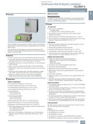
The ULTRAMAT/OXYMAT 6 gas analyzer is a practical combination<br />
of the ULTRAMAT 6 and OXYMAT 6 analyzers in a single enclosure.<br />
The ULTRAMAT 6 channel operates according to the NDIR twobeam<br />
alternating light principle and measures one or two gases<br />
highly selectively whose absorption bands lie in the infrared<br />
wavelength range from 2 to 9 m, such as CO, CO 2 , NO, SO 2 ,<br />
NH 3 , H 2 O as well as CH 4 and other hydrocarbons.<br />
The OXYMAT 6 channel is based on the paramagnetic alternating<br />
pressure method and is used to measure oxygen in gases.<br />
■ Benefits<br />
• Corrosion-resistant materials in gas path (option)<br />
- Measurement possible in highly corrosive sample gases<br />
• Sample chambers can be cleaned as required on site<br />
- Cost savings due to reuse after contamination<br />
• Open interface architecture (RS 485, RS 232, PROFIBUS)<br />
• SIPROM GA network for maintenance and servicing information<br />
(option)<br />
ULTRAMAT channel<br />
• High selectivity with double-layer detector and optical coupler<br />
- Reliable measurements even in complex gas mixtures<br />
• Low detection limits<br />
- Measurements with low concentrations<br />
OXYMAT channel<br />
• Paramagnetic alternating pressure principle<br />
- Small measuring ranges (0 to 0.5 % or 99.5 to 100 % O 2 )<br />
- Absolute linearity<br />
• Detector element has no contact with the sample gas<br />
- Can be used to measure corrosive gases<br />
- Long service life<br />
• Physically suppressed zero through suitable selection of reference<br />
gas (air or O 2 ), e.g. 98 to 100 % O 2 for purity monitoring/air<br />
separation<br />
■ Application<br />
Fields of application<br />
• Measurement for boiler control in incineration plants<br />
• Emission measurements in incineration plants<br />
• Measurement in the automotive industry (test benches)<br />
• Process gas concentrations in chemical plants<br />
• Trace measurements in pure gas processes<br />
• Environmental protection<br />
• TLV (Threshold Limit Value) monitoring at places of work<br />
• Quality monitoring<br />
Special versions<br />
• Special applications<br />
Besides the standard combinations, special applications concerning<br />
material in the gas path, material in the sample cells<br />
(e.g. Titan, Hastelloy C22) and sample components are also<br />
available on request.<br />
• TÜV version/QAL<br />
TÜV-approved versions of the ULTRAMAT/OXYMAT 6 are<br />
available for measurement of CO, NO, SO 2 and O 2 according<br />
to 13th and 17th BlmSchV and TA Luft.<br />
Smallest TÜV-approved and permitted measuring ranges:<br />
- 1-component analyzer<br />
CO: 0 to 50 mg/m 3<br />
NO: 0 to 100 mg/m 3<br />
SO 2 : 0 to 75 mg/m 3<br />
- 2-component analyzer (series connection)<br />
CO: 0 to 75 mg/m 3<br />
NO: 0 to 200 mg/m 3<br />
All larger measuring ranges are also approved.<br />
Furthermore, the TÜV-approved versions of the<br />
ULTRAMAT/OXYMAT 6 comply with the requirements of<br />
EN 14956 and QAL 1 according to EN 14181. Conformity of the<br />
devices with both standards is TÜV-certified.<br />
Determination of the analyzer drift according to EN 14181<br />
(QAL 3) can be carried out manually or also with a PC using the<br />
SIPROM GA maintenance and servicing software. In addition,<br />
selected manufacturers of emission evaluation computers offer<br />
the possibility for downloading the drift data via the analyzer’s<br />
serial interface and to automatically record and process it in the<br />
evaluation computer.<br />
• Flow-type reference compartment<br />
- The flow through the reference compartment should be<br />
adapted to the sample gas flow<br />
- The gas supply of the reduced flow-type reference<br />
compartment should have an upstream pressure of 3 000 to<br />
5 000 hPa (abs.). Then a restrictor will automatically adjust<br />
the flow to approximately 8 hPa<br />
■ Design<br />
19" rack unit<br />
• 19" rack unit with 4 HU for installation<br />
- in hinged frame<br />
- in cabinets with or without telescopic rails<br />
• Front plate can be swung down for servicing purposes<br />
(laptop connection)<br />
• Internal gas paths: hose made of FKM (Viton) or pipe made of<br />
titanium or stainless steel<br />
• Gas connections for sample gas inlet and outlet: pipe diameter<br />
6 mm or 1/4"<br />
• Flow indicator for sample gas on front plate (option)<br />
• Sample chamber (OXYMAT channel) – with or without flowtype<br />
compensation branch – made of stainless steel (mat. no.<br />
1.4571) or of tantalum for highly corrosive sample gases<br />
(e.g. HCl, Cl 2 , SO 2 , SO 3 , etc.)<br />
• Monitoring (option) of sample gas and/or reference gas<br />
(both channels)<br />
1/94 <strong>Siemens</strong> PA 01 · 2014
© <strong>Siemens</strong> AG 2013<br />
Continuous Gas Analyzers, extractive<br />
ULTRAMAT/OXYMAT 6<br />
Display and control panel<br />
• Large LCD panel for simultaneous display of:<br />
- Measured value (digital and analog displays)<br />
- Status bar<br />
- Measuring ranges<br />
• Contrast of LCD panel adjustable using menu<br />
• Permanent LED backlighting<br />
• Washable membrane keyboard with five softkeys<br />
• Menu-driven operation for parameterization, test functions,<br />
adjustment<br />
• User help in plain text<br />
• Graphic display of concentration trend; programmable time<br />
intervals<br />
• Bilingual operating software:<br />
German/English, English/Spanish, French/English,<br />
Italian/English, Spanish/English<br />
General information<br />
Inputs and outputs (per channel)<br />
• One analog output for each measured component<br />
• Two analog inputs freely configurable (e.g. correction of<br />
cross-interference or external pressure sensor)<br />
• Six binary inputs freely configurable (e.g. for measurement<br />
range switchover, processing of external signals from sample<br />
preparation)<br />
• Six relay outputs freely configurable e.g. for fault, maintenance<br />
request, limit alarm, external solenoid valves)<br />
• Expansion by eight additional binary inputs and eight additional<br />
relay outputs e.g. for autocalibration with up to four<br />
calibration gases<br />
Communication<br />
RS 485 present in the basic unit (connection at the rear; for the<br />
rack unit also behind the front plate).<br />
Options<br />
• AK interface for the automotive industry with extended functions<br />
• RS 485/RS 232 converter<br />
• RS 485/Ethernet converter<br />
• RS 485/USB converter<br />
• Connection to networks via PROFIBUS DP/PA interface<br />
• SIPROM GA software as the service and maintenance tool<br />
1<br />
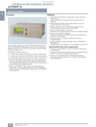
LED backlit graphic<br />
display and<br />
membrane keyboard<br />
with noticeable click<br />
Status line for ULTRAMAT<br />
channel to display the<br />
unit status (programmable)<br />
Display of<br />
concentrations as<br />
numbers and bargraph<br />
(ULTRAMAT channel)<br />
Display of<br />
concentrations as<br />
numbers and bargraph<br />
(OXYMAT channel)<br />
Display of<br />
start-of-scale and<br />
full-scale values<br />
Keyboard to<br />
enter values<br />
Dimensions<br />
selectable<br />
(e.g. ppm, vpm,<br />
%, mg/m³)<br />
Two code levels<br />
according to NAMUR<br />
(maintenance and<br />
specialist level)<br />
Operation with<br />
menu control<br />
using five softkeys<br />
Display of current<br />
measuring ranges<br />
Status line for<br />
OXYMAT channel<br />
to display the<br />
unit status<br />
(programmable)<br />
ESC key<br />
to abort inputs<br />
INFO key<br />
for help in plain text<br />
CLEAR key<br />
to delete inputs<br />
ENTER key<br />
to accept<br />
input values<br />
MEAS key<br />
to return to<br />
measurement mode<br />
ULTRAMAT/OXYMAT 6, membrane keyboard and graphic display<br />
<strong>Siemens</strong> PA 01 · 2014<br />
1/95
© <strong>Siemens</strong> AG 2013<br />
Continuous Gas Analyzers, extractive<br />
ULTRAMAT/OXYMAT 6<br />
General information<br />
1 Designs – Parts touched by sample gas, standard<br />
Gas path ULTRAMAT channel<br />
19" rack unit<br />
With hoses Bushing Stainless steel, mat. no. 1.4571<br />
Hose<br />
FKM (e.g. Viton)<br />
Sample chamber:<br />
•Body<br />
Aluminum<br />
• Lining<br />
Aluminum<br />
• Fitting Stainless steel, mat. no. 1.4571,<br />
O-ring: FKM (e.g. Viton) or FFKM (Kalrez)<br />
•Window CaF 2 , adhesive: E353,<br />
O-ring: FKM (e.g. Viton) or FFKM (Kalrez)<br />
With pipes Bushing Titanium<br />
Pipe<br />
Titanium,<br />
O-ring: FKM (e.g. Viton) or FFKM (Kalrez)<br />
Sample chamber:<br />
•Body<br />
Aluminum<br />
• Lining<br />
Tantalum (only for cell length 20 mm to 180 mm)<br />
•Window CaF 2 , adhesive: E353,<br />
O-ring: FKM (e.g. Viton) or FFKM (Kalrez)<br />
With pipes Bushing Stainless steel, mat. no. 1.4571<br />
Pipe Stainless steel, mat. no. 1.4571,<br />
O-ring: FKM (e.g. Viton) or FFKM (Kalrez)<br />
Sample chamber:<br />
•Body<br />
Aluminum<br />
• Lining<br />
Aluminum or tantalum (Ta: only for cell length 20 mm to 180 mm)<br />
•Window CaF 2 , adhesive: E353,<br />
O-ring: FKM (e.g. Viton) or FFKM (Kalrez)<br />
Flow indicator Measurement pipe Duran glass<br />
Variable area<br />
Duran glass<br />
Suspension boundary PTFE (Teflon)<br />
Angle pieces<br />
FKM (e.g. Viton)<br />
Pressure switch Membrane FKM (e.g. Viton)<br />
Enclosure PA 6.3T<br />
Options<br />
Gas path ULTRAMAT channel<br />
19" rack unit<br />
Flow indicator Measurement pipe Duran glass<br />
Variable area<br />
Duran glass<br />
Suspension boundary PTFE (Teflon)<br />
Angle pieces<br />
FKM (e.g. Viton)<br />
Pressure switch Membrane FKM (e.g. Viton)<br />
Enclosure PA 6.3T<br />
Versions – Parts wetted by sample gas, special applications (examples)<br />
Gas path ULTRAMAT channel<br />
19" rack unit<br />
With pipes Bushing e.g. Hastelloy C22<br />
Pipe e.g. Hastelloy C22,<br />
O-ring: FKM (e.g. Viton) or FFKM (Kalrez)<br />
Sample chamber:<br />
•Body<br />
e.g. Hastelloy C22<br />
•Window<br />
CaF 2 , without adhesive<br />
O-ring: FKM (e.g. Viton) or FFKM (Kalrez)<br />
1/96 <strong>Siemens</strong> PA 01 · 2014
© <strong>Siemens</strong> AG 2013<br />
Continuous Gas Analyzers, extractive<br />
ULTRAMAT/OXYMAT 6<br />
Designs – Parts touched by sample gas, standard<br />
Gas path OXYMAT channel<br />
With hoses Bushing<br />
Hose<br />
Sample chamber<br />
Fittings for sample chamber<br />
Restrictor<br />
O-rings<br />
With pipes Bushing<br />
Pipe<br />
Sample chamber<br />
Restrictor<br />
O-rings<br />
With pipes Bushing<br />
Pipe<br />
Sample chamber<br />
Restrictor<br />
O-rings<br />
With pipes Bushing<br />
Pipe<br />
Sample chamber<br />
Restrictor<br />
O-rings<br />
Options<br />
Gas path ULTRAMAT channel<br />
and OXYMAT channel<br />
19" rack unit<br />
Stainless steel, mat. no. 1.4571<br />
FKM (e.g. Viton)<br />
Stainless steel, mat. no. 1.4571 or tantalum<br />
Stainless steel, mat. no. 1.4571<br />
PTFE (e.g. Teflon)<br />
FKM (e.g. Viton)<br />
Titanium<br />
Titanium<br />
Stainless steel, mat. no. 1.4571 or Tantalum<br />
Titanium<br />
FKM (Viton) or FFKM (Kalrez)<br />
Stainless steel, mat. no. 1.4571<br />
Stainless steel, mat. no. 1.4571<br />
Stainless steel, mat. no. 1.4571 or Tantalum<br />
Stainless steel, mat. no. 1.4571<br />
FKM (Viton) or FFKM (Kalrez)<br />
Hastelloy C 22<br />
Hastelloy C 22<br />
Stainless steel, mat. no. 1.4571 or Tantalum<br />
Hastelloy C 22<br />
FKM (e.g. Viton) or FFKM (e.g. Kalrez)<br />
19" rack unit<br />
General information<br />
1<br />
Flow indicator Measurement pipe Duran glass<br />
Variable area<br />
Duran glass<br />
Suspension boundary<br />
PTFE (Teflon)<br />
Angle pieces<br />
FKM (e.g. Viton)<br />
Pressure switch Membrane FKM (e.g. Viton)<br />
Enclosure PA 6.3T<br />
<strong>Siemens</strong> PA 01 · 2014<br />
1/97
© <strong>Siemens</strong> AG 2013<br />
Continuous Gas Analyzers, extractive<br />
ULTRAMAT/OXYMAT 6<br />
General information<br />
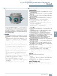
1 Gas path<br />
Legend for the gas path figures<br />
1 Sample gas inlet (OXYMAT channel) 10 Connection of pressure sensor (ULTRAMAT channel)<br />
2 Sample gas outlet (OXYMAT channel) 11 Restrictor (in reference gas inlet)<br />
3 Not used 12 O 2 physical system<br />
4 Reference gas inlet 13 Pressure sensor<br />
5 Sample gas inlet (ULTRAMAT channel) 14 Pressure switch in sample gas path (option)<br />
6 Sample gas outlet (ULTRAMAT channel) 15 Flow indicator in sample gas path (option)<br />
7 Reference gas outlet (ULTRAMAT channel, option) 16 IR physical system<br />
8 Reference gas inlet (ULTRAMAT channel, option) 17 Filter<br />
9 Purging gas 18 Pressure switch (reference gas) (option)<br />
9 10 5 6 1 2 4<br />
17<br />
18<br />
P<br />
11<br />
13<br />
12<br />
P<br />
16<br />
P<br />
14<br />
P<br />
14<br />
P 13<br />
F<br />
F<br />
15 15<br />
ULTRAMAT/OXYMAT 6, gas path (example) IR channel without flow-type reference side<br />
9 10 5 6 8 7 1 2 4<br />
17<br />
18<br />
P<br />
11<br />
12<br />
13<br />
P<br />
16<br />
P<br />
14<br />
P<br />
14<br />
P 13<br />
F<br />
F<br />
15 15<br />
ULTRAMAT/OXYMAT 6, gas path (example) IR channel with flow-type reference side<br />
1/98 <strong>Siemens</strong> PA 01 · 2014
© <strong>Siemens</strong> AG 2013<br />
Continuous Gas Analyzers, extractive<br />
ULTRAMAT/OXYMAT 6<br />
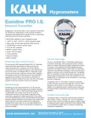
■ Function<br />
Principle of operation, ULTRAMAT channel<br />
The ULTRAMAT channel operates according to the infrared twobeam<br />
alternating light principle with double-layer detector and<br />
optical coupler.<br />
The measuring principle is based on the molecule-specific absorption<br />
of bands of infrared radiation. The absorbed wavelengths<br />
are characteristic to the individual gases, but may partially<br />
overlap. This results in cross-sensitivities which are<br />
reduced to a minimum by the following measures:<br />
• Gas-filled filter cell (beam divider)<br />
• Double-layer detector with optical coupler<br />
• Optical filters if necessary<br />
The figure shows the measuring principle. An IR source (1)<br />
which is heated to approx. 700 ºC and which can be shifted to<br />
balance the system is divided by the beam divider (3) into two<br />
equal beams (sample and reference beams). The beam divider<br />
also acts as a filter cell.<br />
The reference beam passes through a reference cell (8) filled<br />
with N 2 (a non-infrared-active gas) and reaches the right-hand<br />
side of the detector (11) practically unattenuated. The sample<br />
beam passes through the sample chamber (7) through which<br />
the sample gas flows and reaches the left-hand side of the detector<br />
(10) attenuated to a lesser or greater extent depending on<br />
the concentration of the sample gas. The detector is filled with a<br />
defined concentration of the gas component to be measured.<br />
The detector is designed as a double-layer detector. The center<br />
of the absorption band is preferentially absorbed in the upper<br />
detector layer, the edges of the band are absorbed to approximately<br />
the same extent in the upper and lower layers. The upper<br />
and lower detector layers are connected together via the microflow<br />
sensor (12). This coupling means that the spectral sensitivity<br />
has a very narrow band.<br />
The optical coupler (13) lengthens the lower receiver cell layer<br />
optically. The infrared absorption in the second detector layer is<br />
varied by changing the slider position (14). It is thus possible to<br />
individually minimize the influence of interfering components.<br />
A chopper (5) rotates between the beam divider and the sample<br />
chamber and interrupts the two beams alternately and periodically.<br />
If absorption takes place in the sample chamber, a pulsating<br />
flow is generated between the two detector levels which is<br />
converted by the microflow sensor (12) into an electric signal.<br />
The microflow sensor consists of two nickel-plated grids heated<br />
to approximately 120 ºC, which, along with two supplementary<br />
resistors, form a Wheatstone bridge. The pulsating flow together<br />
with the dense arrangement of the Ni grids causes a change in<br />
resistance. This leads to an offset in the bridge, which is dependent<br />
on the concentration of the sample gas.<br />
Note<br />
The sample gases must be fed into the analyzers free of dust.<br />
Condensation should be prevented from occurring in the sample<br />
chambers. Therefore, the use of gas modified for the measuring<br />
task is necessary in most application cases.<br />
As far as possible, the ambient air of the analyzer should not<br />
have a large concentration of the gas components to be measured.<br />
Flow-type reference sides with reduced flow must not be operated<br />
with flammable or toxic gases.<br />
Flow-type reference sides with reduced flow and an O 2 content<br />
> 70 % may only be used together with Y02.<br />
1<br />
2<br />
3<br />
5<br />
6<br />
7<br />
9<br />
General information<br />
10 11<br />
1 IR source, adjustable 8 Reference cell<br />
2 Optical filter 9 Sample gas outlet<br />
3 Beam divider 10 Detector, meas. side<br />
4 Eddy current drive 11 Detector, reference side<br />
5 Chopper 12 Microflow sensor<br />
6 Sample gas inlet 13 Optical coupler<br />
7 Sample cell 14 Slider, adjustable<br />
ULTRAMAT channel, principle of operation<br />
Channels with electronically suppressed zero point only differ<br />
from the standard version in the measuring range parameterization.<br />
Physically suppressed zeros can be provided as a special application.<br />
4<br />
8<br />
12<br />
13<br />
14<br />
1<br />
<strong>Siemens</strong> PA 01 · 2014<br />
1/99
© <strong>Siemens</strong> AG 2013<br />
Continuous Gas Analyzers, extractive<br />
ULTRAMAT/OXYMAT 6<br />
1 Principle of operation, OXYMAT channel<br />
In contrast to almost all other gases, oxygen is paramagnetic.<br />
This property is utilized as the measuring principle by the<br />
OXYMAT channel.<br />
Oxygen molecules in an inhomogeneous magnetic field are<br />
drawn in the direction of increased field strength due to their<br />
paramagnetism. When two gases with different oxygen contents<br />
meet in a magnetic field, a pressure difference is produced<br />
between them.<br />
One gas (1) is a reference gas (N 2 , O 2 or air), the other is the<br />
sample gas (5). The reference gas is introduced into the sample<br />
chamber (6) through two channels (3). One of these reference<br />
gas streams meets the sample gas within the area of a magnetic<br />
field (7). Because the two channels are connected, the pressure,<br />
which is proportional to the oxygen content, causes a cross flow.<br />
This flow is converted into an electric signal by a microflow sensor<br />
(4).<br />
The microflow sensor consists of two nickel-plated grids heated<br />
to approximately 120 ºC, which, along with two supplementary<br />
resistors, form a Wheatstone bridge. The pulsating flow results<br />
in a change in the resistance of the Ni grids. This leads to an offset<br />
in the bridge which is dependent on the oxygen concentration<br />
of the sample gas.<br />
Because the microflow sensor is located in the reference gas<br />
stream, the measurement is not influenced by the thermal conductivity,<br />
the specific heat or the internal friction of the sample<br />
gas. This also provides a high degree of corrosion resistance<br />
because the microflow sensor is not exposed to the direct influence<br />
of the sample gas.<br />
By using a magnetic field with alternating strength (8), the effect<br />
of the background flow in the microflow sensor is not detected,<br />
and the measurement is thus independent of the instrument’s<br />
operating position.<br />
The sample chamber is directly in the sample path and has a<br />
small volume, and the microflow sensor is a low-lag sensor. This<br />
results in a very short response time.<br />
Vibrations frequently occur at the place of installation and may<br />
falsify the measured signal (noise). A further microflow sensor<br />
(10) through which no gas passes acts as a vibration sensor. Its<br />
signal is applied to the measured signal as compensation.<br />
If the density of the sample gas deviates by more than 50 % from<br />
that of the reference gas, the compensation microflow sensor<br />
(10) is flushed with reference gas just like the measuring sensor<br />
(4) (option).<br />
Note<br />
The sample gases must be fed into the analyzers free of dust.<br />
Condensation should be prevented from occurring in the sample<br />
chambers. Therefore, gas modified for the measuring tasks is<br />
necessary in most application cases.<br />
<br />
<br />
<br />
<br />
<br />
D<br />
<br />
<br />
<br />
<br />
<br />
<br />
<br />
<br />
<br />
1 Reference gas inlet<br />
2 Restrictors<br />
3 Reference gas channels<br />
4 Microflow sensor for measurement<br />
5 Sample gas inlet<br />
6 Sample cell<br />
7 Paramagnetic effect<br />
8 Electromagnet with alternating field strength<br />
9 Sample gas and reference gas outlet<br />
10 Microflow sensor in compensation system<br />
(without flow)<br />
<br />
<br />
<br />
<br />
General information<br />
OXYMAT channel, principle of operation<br />
1/100 <strong>Siemens</strong> PA 01 · 2014
© <strong>Siemens</strong> AG 2013<br />
Continuous Gas Analyzers, extractive<br />
ULTRAMAT/OXYMAT 6<br />
Essential characteristics<br />
• Dimension of measured value freely selectable (e.g. vpm,<br />
mg/m 3 )<br />
• Four freely-parameterizable measuring ranges per component<br />
• Measuring ranges with suppressed zero point possible<br />
• Measuring range identification<br />
• Galvanically isolated signal output 0/2/4 to 20 mA per component<br />
• Automatic or manual measuring range switchover selectable;<br />
remote switching is also possible<br />
• Storage of measured values possible during adjustments<br />
• Time constants selectable within wide limits (static/dynamic<br />
noise suppression); i.e. the response time of the analyzer or<br />
component can be matched to the respective measuring task<br />
• Short response time<br />
• Low long-term drift<br />
• Measuring point switchover for up to 6 measuring points<br />
(programmable)<br />
• Measuring point identification<br />
• Monitoring of sample gas flow (option)<br />
• Two control levels with separate authorization codes to prevent<br />
unintentional and unauthorized inputs<br />
• Automatic, parameterizable measuring range calibration<br />
• Simple handling using a numerical membrane keyboard and<br />
operator prompting<br />
• Operation based on NAMUR recommendation<br />
• Customer-specific analyzer options such as:<br />
- Customer acceptance<br />
-TAG labels<br />
- Drift recording<br />
General information<br />
ULTRAMAT channel<br />
• Differential measuring ranges with flow-type reference cell<br />
• Internal pressure sensor for correction of variations in atmospheric<br />
pressure in the range 700 to 1 200 hPa absolute<br />
• External pressure sensor - only with piping as the gas path -<br />
can be connected for correction of variations in the process<br />
gas pressure in the range 700 to 1 500 hPa absolute (option)<br />
• Sample chambers for use in presence of highly corrosive sample<br />
gases (e.g. tantalum layer or Hastelloy C22)<br />
OXYMAT channel<br />
• Monitoring of sample gas and/or reference gas (option)<br />
• Different smallest measuring ranges (0.5 %, 2.0 % or<br />
5.0 % O 2 )<br />
• Analyzer unit with flow-type compensation circuit (option): a<br />
flow is passed through the compensation branch to reduce<br />
the vibration dependency in the case of highly different densities<br />
of the sample and reference gases<br />
• Internal pressure sensor for correction of pressure variations<br />
in sample gas (range 500 to 2 000 hPa absolute)<br />
• External pressure sensor - only with piping as the gas path -<br />
can be connected for correction of variations in the sample<br />
gas pressure up to 3 000 hPa absolute (option)<br />
• Monitoring of reference gas with reference gas connection<br />
3 000 to 5 000 hPa (option), absolute<br />
• Sample chamber for use in presence of highly corrosive sample<br />
gases<br />
1<br />
<strong>Siemens</strong> PA 01 · 2014<br />
1/101
© <strong>Siemens</strong> AG 2013<br />
Continuous Gas Analyzers, extractive<br />
ULTRAMAT/OXYMAT 6<br />
1 Reference gases<br />
Measuring range Recommended reference gas Reference gas connection<br />
pressure<br />
0 to ... vol.% O 2 N 2 2 000 … 4 000 hPa above sample<br />
gas pressure (max. 5 000 hPa<br />
... to 100 vol.% O 2 (suppressed O 2<br />
absolute)<br />
zero point with full-scale value<br />
100 vol. % O 2 )<br />
Around 21 vol.% O 2 (suppressed Air<br />
100 hPa with respect to sample gas<br />
zero point with 21 vol.% O 2 within<br />
pressure which may vary by max.<br />
the measuring span)<br />
50 hPa around the atmospheric<br />
pressure<br />
Remarks<br />
The reference gas flow is set automatically<br />
to 5 … 10 ml/min (up to<br />
20 ml/min with flow-type compensation<br />
branch)<br />
General information<br />
Table 1: Reference gases for OXYMAT channel<br />
Correction of zero error / cross-sensitivities (OXYMAT channel)<br />
Accompanying gas<br />
(concentration 100 vol.%)<br />
Organic gases<br />
Deviation from zero point in<br />
vol.% O 2 absolute<br />
Table 2: Zero point error due to diamagnetism or paramagnetism of some accompanying gases with reference to nitrogen at 60 °C und 1 000 hPa<br />
absolute (according to IEC 1207/3)<br />
Conversion to other temperatures:<br />
The deviations from the zero point listed in Table 2 must be multiplied by a correction factor (k):<br />
• with diamagnetic gases: k = 333 K / ( [°C] + 273 K)<br />
• with paramagnetic gases: k = [333 K / ( [°C] + 273 K)] 2<br />
(All diamagnetic gases have a negative deviation from zero point)<br />
Accompanying gas<br />
(concentration 100 vol.%)<br />
Inert gases<br />
Ethane C 2 H 6 -0.49 Helium He +0.33<br />
Ethene (ethylene) C 2 H 4 -0.22 Neon Ne +0.17<br />
Ethine (acetylene) C 2 H 2 -0.29 Argon Ar -0.25<br />
1.2 butadiene C 4 H 6 -0.65 Krypton Kr -0.55<br />
1.3 butadiene C 4 H 6 -0.49 Xenon Xe -1.05<br />
n-butane C 4 H 10 -1.26<br />
iso-butane C 4 H 10 -1.30 Inorganic gases<br />
1-butene C 4 H 8 -0.96 Ammonia NH 3 -0.20<br />
iso-butene C 4 H 8 -1.06 Hydrogen bromide HBr -0.76<br />
Dichlorodifluoromethane (R12) CCl 2 F 2 -1.32 Chlorine Cl 2 -0.94<br />
Acetic acid CH 3 COOH -0.64 Hydrogen chloride HCl -0.35<br />
n-heptane C 7 H 16 -2.40 Dinitrogen monoxide N 2 O -0.23<br />
n-hexane C 6 H 14 -2.02 Hydrogen fluoride HF +0.10<br />
Cyclo-hexane C 6 H 12 -1.84 Hydrogen iodide HI -1.19<br />
Methane CH 4 -0.18 Carbon dioxide CO 2 -0.30<br />
Methanol CH 3 OH -0.31 Carbon monoxide CO +0.07<br />
n-octane C 8 H 18 -2.78 Nitrogen oxide NO +42.94<br />
n-pentane C 5 H 12 -1.68 Nitrogen N 2 0.00<br />
iso-pentane C 5 H 12 -1.49 Nitrogen dioxide NO 2 +20.00<br />
Propane C 3 H 8 -0.87 Sulfur dioxide SO 2 -0.20<br />
Propylene C 3 H 6 -0.64 Sulfur hexafluoride SF 6 -1.05<br />
Trichlorofluoromethane (R11) CCl 3 F -1.63 Hydrogen sulfide H 2 S -0.44<br />
Vinyl chloride C 2 H 3 Cl -0.77 Water H 2 O -0.03<br />
Vinyl fluoride C 2 H 3 F -0.55 Hydrogen H 2 +0.26<br />
1.1 vinylidene chloride C 2 H 2 Cl 2 -1.22<br />
Deviation from zero point in<br />
vol.% O 2 absolute<br />
1/102 <strong>Siemens</strong> PA 01 · 2014
© <strong>Siemens</strong> AG 2013<br />
Continuous Gas Analyzers, extractive<br />
ULTRAMAT/OXYMAT 6<br />
■ Technical specifications<br />
ULTRAMAT/OXYMAT 6, 19" rack unit<br />
General information<br />
Operating position<br />
Front wall, vertical<br />
Conformity<br />
CE mark in accordance with<br />
EN 50081-1, EN 50082-2<br />
Design, enclosure<br />
Weight<br />
Approx. 21 kg<br />
Degree of protection IP20 according to EN 60529<br />
Electrical characteristics<br />
EMC<br />
(Electromagnetic Compatibility)<br />
In accordance with standard<br />
requirements of NAMUR NE21<br />
(08/98)<br />
Electrical safety According to EN 61010-1,<br />
overvoltage category III<br />
Power supply<br />
100 ... 120 V AC (nominal range<br />
of use 90 ... 132 V), 48 ... 63 Hz or<br />
200 ... 240 V AC (nominal range<br />
of use 180 ... 264 V), 48 ... 63 Hz<br />
Power consumption<br />
Approx. 70 VA<br />
Fuse values<br />
120 ... 120 V: F1/F2 = T 1.6 A<br />
200...240V: F1/F2 = T1A<br />
Electrical inputs and outputs (per channel)<br />
Analog output<br />
0/2/4 ... 20 mA, isolated;<br />
max. load 750 <br />
Relay outputs<br />
6, with changeover contacts,<br />
freely parameterizable, e.g. for<br />
measuring range identification;<br />
load: 24 V AC/DC/1 A, isolated,<br />
non-sparking<br />
Analog inputs<br />
2, dimensioned for<br />
0/2/4 … 20 mA for external pressure<br />
sensor and correction of<br />
influence of accompanying gas<br />
(correction of cross-interference)<br />
Binary inputs<br />
6, designed for 24 V, isolated,<br />
freely parameterizable, e.g. for<br />
measuring range switchover<br />
Serial interface RS 485<br />
Options<br />
AUTOCAL function each with<br />
8 additional binary inputs and<br />
relay outputs, also with<br />
PROFIBUS PA or PROFIBUS DP<br />
Climatic conditions<br />
Permissible ambient temperature -30 ... +70 °C during storage and<br />
transportation, 5 … 45 °C during<br />
operation<br />
Permissible humidity<br />
< 90 % relative humidity, during<br />
storage and transportation (dew<br />
point must not be undershot)<br />
19" rack unit<br />
Technical data, ULTRAMAT channel<br />
Measuring ranges<br />
4, internally and externally switchable;<br />
autoranging is also possible<br />
Smallest possible measuring range Dependent on the application,<br />
e.g.<br />
CO: 0 ... 10 vpm<br />
CO 2 : 0 ... 5 vpm<br />
Largest possible measuring range Dependent on the application<br />
Measuring ranges with suppressed<br />
zero point<br />
Any zero point within 0 ... 100<br />
vol.% can be implemented; smallest<br />
possible span 20 %<br />
Linearized<br />
Characteristic<br />
Influence of interfering gases must be considered separately<br />
Gas inlet conditions<br />
Permissible sample gas pressure<br />
• Without pressure switch<br />
700 ... 1 500 hPa (absolute)<br />
• With integrated pressure switch 700 ... 1 300 hPa (absolute)<br />
Sample gas flow<br />
18 ... 90 l/h (0.3 ... 1.5 l/min)<br />
Sample gas temperature<br />
Min. 0 to max. 50 °C, but above<br />
the dew point<br />
Sample gas humidity<br />
Dynamic response<br />
Warm-up period<br />
Delayed display (T 90 -time)<br />
Damping (electrical time constant)<br />
Dead time (purging time of the gas<br />
path in the unit at 1 l/min)<br />
Time for device-internal signal<br />
processing<br />
Pressure correction range<br />
Pressure sensor<br />
• Internal<br />
• External<br />
< 90 % (relative humidity), or<br />
dependent on measuring task,<br />
non-condensing<br />
At room temperature < 30 min<br />
(the technical specification will be<br />
met after 2 hours)<br />
Dependent on length of analyzer<br />
chamber, sample gas line and<br />
parameterizable damping<br />
0 ... 100 s, parameterizable<br />
Approx. 0.5 ... 5 s, depending on<br />
version<br />
© <strong>Siemens</strong> AG 2013<br />
Continuous Gas Analyzers, extractive<br />
ULTRAMAT/OXYMAT 6<br />
1 Influencing variables (relating to sample gas pressure 1 013 hPa<br />
absolute, 0.5 l/min sample gas flow and 25 °C ambient temperature)<br />
Ambient temperature<br />
< 1 % of current measuring<br />
range/10 K (with constant<br />
receiver cell temperature)<br />
Sample gas pressure<br />
• When pressure compensation<br />
has been switched on: < 0.15 %<br />
of the span/1 % change in atmospheric<br />
pressure<br />
• When pressure compensation<br />
has been switched off: < 1.5 %<br />
of the span/1 % change in atmospheric<br />
pressure<br />
Sample gas flow<br />
Negligible<br />
Power supply<br />
< 0.1 % of the current measuring<br />
range with rated voltage 10 %<br />
Environmental conditions<br />
Application-specific measuring<br />
influences possible if ambient air<br />
contains measured component or<br />
cross interference-sensitive<br />
gases<br />
Technical data, OXYMAT channel<br />
Measuring ranges<br />
Smallest possible span (relating to<br />
sample gas pressure 1 000 hPa<br />
absolute, 0.5 l/min sample gas flow<br />
and 25 °C ambient temperature)<br />
Largest possible measuring range 100 vol.% O 2<br />
Measuring ranges with suppressed<br />
zero point<br />
4, internally and externally switchable;<br />
automatic measuring range<br />
switchover also possible<br />
0.5 vol.%, 2 vol.% or 5 vol.% O 2<br />
Any zero point within<br />
0 ... 100 vol.% can be implemented,<br />
provided that a suitable<br />
reference gas is used<br />
Gas inlet conditions<br />
Permissible sample gas pressure<br />
• With pipes<br />
500 ... 3 000 hPa absolute<br />
• With hoses<br />
- Without pressure switch 500 ... 1 500 hPa absolute<br />
- With pressure switch 500 ... 1 300 hPa absolute<br />
Sample gas flow<br />
18 ... 60 l/h (0.3 ... 1 l/min)<br />
Sample gas temperature 0 ... 50 ºC<br />
Sample gas humidity<br />
< 90 % RH (relative humidity)<br />
Reference gas pressure<br />
(high-pressure version)<br />
Reference gas pressure<br />
(low-pressure version)<br />
Dynamic response<br />
Warm-up period<br />
Delayed display (T 90 time)<br />
Damping (electrical time constant)<br />
Dead time (purging time of the gas<br />
path in the unit at 1 l/min)<br />
Time for device-internal signal<br />
processing<br />
2 000 ... 4 000 hPa above sample<br />
gas pressure, but max.<br />
5000hPa<br />
Min. 100 hPa above sample gas<br />
pressure<br />
At room temperature < 30 min<br />
(the technical specification will be<br />
met after 2 hours)<br />
Min. 1.5 ... 3.5 s, depending on<br />
version<br />
0 ... 100 s, parameterizable<br />
Approx. 0.5 ... 2.5 s, depending<br />
on version<br />
© <strong>Siemens</strong> AG 2013<br />
Continuous Gas Analyzers, extractive<br />
ULTRAMAT/OXYMAT 6<br />
■<br />
Selection and ordering data<br />
Article No.<br />
ULTRAMAT/OXYMAT 6 gas analyzer<br />
7MB2023- 77777- 7 777 Cannot be combined<br />
Combined measurement of IR-absorbing gas and O 2<br />
19" rack unit for installation in cabinets<br />
Gas connections for sample gas and reference gas<br />
Pipe with 6 mm outer diameter 0 0 A21<br />
Pipe with ¼" outer diameter 1 1 A20<br />
19" rack unit<br />
1<br />
Smallest possible measuring span O 2<br />
0,5 % reference gas pressure 3 000 hPa A<br />
0,5 % reference gas pressure 100 hPa (external pump) B B B A26, Y02<br />
2 % reference gas pressure 3 000 hPa C<br />
2 % reference gas pressure 100 hPa (external pump) D D D A26, Y02<br />
5% reference gas pressure 3 000 hPa E<br />
5% reference gas pressure 100 hPa (external pump) F F F A26, Y02<br />
Sample chamber (OXYMAT channel)<br />
Non-flow-type compensation branch<br />
• Made of stainless steel, mat. no. 1.4571<br />
A<br />
• Made of tantalum<br />
B<br />
Flow-type compensation branch<br />
• Made of stainless steel, mat. no. 1.4571 C C<br />
• Made of tantalum D D<br />
Internal gas paths<br />
(both channels)<br />
Hose made of FKM<br />
(Viton)<br />
Sample chamber 1)<br />
(lining)<br />
(ULTRAMAT channel)<br />
Reference chamber<br />
(flow-type)<br />
(ULTRAMAT channel)<br />
Aluminum Non-flow-type 0 0 0 A20, A21<br />
Aluminum Flow-type 1 1<br />
Pipe made of titanium Tantalum Non-flow-type 4 4 A20, A21, Y02<br />
Tantalum Flow-type 5 5 Y02<br />
Stainless steel pipe<br />
(mat. no. 1.4571)<br />
Aluminum Non-flow-type 6 6 A20, A21<br />
Tantalum Non-flow-type 8 8 A20, A21<br />
With sample gas monitoring (both channels)<br />
Hose made of FKM<br />
(Viton)<br />
Aluminum Non-flow-type 2 2 2 A20, A21<br />
Aluminum Flow-type 3 3<br />
Add-on electronics<br />
Without 0<br />
AUTOCAL function<br />
• With 8 additional digital inputs and outputs for OXYMAT channel 1<br />
• With 8 additional digital inputs and outputs for ULTRAMAT channel 2<br />
• With 8 additional digital inputs and 8 additional digital outputs for<br />
3<br />
ULTRAMAT channel and OXYMAT channel<br />
• With serial interface for the automotive industry (AK) 5 5 Y02<br />
• With 8 additional digital inputs/outputs<br />
6<br />
and PROFIBUS PA interface for<br />
ULTRAMAT channel and OXYMAT channel<br />
• With 8 additional digital inputs/outputs<br />
7<br />
and PROFIBUS DP interface for<br />
ULTRAMAT channel and OXYMAT channel<br />
Power supply<br />
100 ... 120 V AC, 48 ... 63 Hz 0<br />
200 ... 240 V AC, 48 ... 63 Hz 1<br />
Footnotes, see next page<br />
<strong>Siemens</strong> PA 01 · 2014<br />
1/105
© <strong>Siemens</strong> AG 2013<br />
Continuous Gas Analyzers, extractive<br />
ULTRAMAT/OXYMAT 6<br />
1<br />
19" rack unit<br />
■<br />
Selection and ordering data<br />
ULTRAMAT channel<br />
Measured component<br />
Possible with measuring<br />
range identification<br />
CO 11 2) , 12 ... 30 A<br />
CO highly selective (with optical filter) 12 2) , 13 ... 30 B<br />
CO (TÜV; see table "TÜV single component (IR channel)", page 1/111)<br />
X<br />
CO 2 10 2) , 11 ... 30 C<br />
CH 4 13 2) , 14 ... 30 D<br />
C 2 H 2 15 2) , 16 ... 30 E<br />
C 2 H 4 15 2) , 16 ... 30 F<br />
C 2 H 6 14 2) , 15 ... 30 G<br />
C 3 H 6 14 2) , 15 ... 30 H<br />
C 3 H 8 13 2) , 14 ... 30 J<br />
C 4 H 6 15 2) , 16 ... 30 K<br />
C 4 H 10 14 2) , 15 ... 30 L<br />
C 6 H 14 14 2) , 15 ... 30 M<br />
SO 2 (TÜV; see table "TÜV single component 13 2) , 14 ... 30 N<br />
(IR channel)", page 1/111)<br />
NO (TÜV; see table "TÜV single component 14 2) , 15 ... 20, 22 P<br />
(IR channel)", page 1/111)<br />
NH 3 (dry) 14 2) , 15 ... 30 Q Q<br />
H 2 O 17 2) , 18 ... 20, 22 R R<br />
N 2 O 13 2) , 14 ... 30 S<br />
Smallest measuring<br />
range<br />
Largest measuring<br />
range<br />
Measuring range<br />
identification<br />
0 ... 5 vpm 0 ... 100 vpm 10 A<br />
0 ... 10 vpm 0 ... 200 vpm 11 B<br />
0 ... 20 vpm 0 ... 400 vpm 12 C<br />
0 ... 50 vpm 0 ... 1 000 vpm 13 D<br />
0 ... 100 vpm 0 ... 1 000 vpm 14 E<br />
0 ... 300 vpm 0 ... 3 000 vpm 15 F<br />
0 ... 500 vpm 0 ... 5 000 vpm 16 G<br />
0 ... 1 000 vpm 0 ... 10 000 vpm 17 H<br />
0 ... 3 000 vpm 0 ... 10 000 vpm 18 J<br />
0 ... 3 000 vpm 0 ... 30 000 vpm 19 K<br />
0 ... 5 000 vpm 0 ... 15 000 vpm 20 L<br />
0 ... 5 000 vpm 0 ... 50 000 vpm 21 M<br />
0 ... 1 % 0 ... 3 % 22 N<br />
0 ... 1 % 0 ... 10 % 23 P<br />
0 ... 3 % 0 ... 10 % 24 Q<br />
0 ... 3 % 0 ... 30 % 25 R<br />
0 ... 5 % 0 ... 15 % 26 S<br />
0 ... 5 % 0 ... 50 % 27 T<br />
0 ... 10 % 0 ... 30 % 28 U<br />
0 ... 10 % 0 ... 100 % 29 V<br />
0 ... 30 % 0 ... 100 % 30 W<br />
Operating software and documentation<br />
German 0<br />
English 1<br />
French 2<br />
Spanish 3<br />
Italian 4<br />
1) Only for cell length 20 to 180 mm<br />
2) Can be ordered as special application (no. 3100 with order code Y12)<br />
Article No.<br />
ULTRAMAT/OXYMAT 6 gas analyzer<br />
7MB2023- 77777- 7 777 Cannot be combined<br />
Combined measurement of IR-absorbing gas and O 2<br />
19" rack unit for installation in cabinets<br />
1/106 <strong>Siemens</strong> PA 01 · 2014
© <strong>Siemens</strong> AG 2013<br />
Continuous Gas Analyzers, extractive<br />
ULTRAMAT/OXYMAT 6<br />
19" rack unit<br />
■ Selection and ordering data<br />
Additional versions Order code Cannot be combined<br />
Add "-Z" to Article No. and specify Order codes.<br />
Flow-type reference cell with reduced flow, 6 mm<br />
A20<br />
(ULTRAMAT channel) 1)<br />
Flow-type reference cell with reduced flow, ¼"<br />
A21<br />
(ULTRAMAT channel) 1)<br />
Reference gas monitoring (pressure switch ... 3 000 hPa),<br />
A26<br />
for OXYMAT channel only<br />
Connection pipes<br />
(can only be combined with the appropriate gas connection diameter and internal gas path<br />
materials)<br />
• Titanium connection pipe, 6 mm,<br />
A22<br />
complete with screwed gland, for sample gas side<br />
• Titanium connection pipe, ¼",<br />
A24<br />
complete with screwed gland, for sample gas side<br />
• Stainless steel connection pipe (mat. no. 1.4571), 6 mm,<br />
A27<br />
complete with screwed gland, for sample gas side<br />
• Stainless steel connection pipe (mat. no. 1.4571), ¼",<br />
A29<br />
complete with screwed gland, for sample gas side<br />
Telescopic rails (2 units)<br />
A31<br />
Set of Torx screwdrivers<br />
A32<br />
Kalrez gaskets in sample gas path (O 2 side)<br />
B01<br />
TAG labels (specific lettering based on customer information)<br />
B03<br />
Kalrez gaskets in sample gas path (IR side)<br />
B04<br />
FM/CSA certificate – Class I Div 2<br />
E20<br />
Clean for O 2 service (specially cleaned gas path)<br />
Y02<br />
(ULTRAMAT channel and OXYMAT channel)<br />
Measuring range indication in plain text 2) , if different from the standard setting<br />
Y11<br />
Special setting (only in conjunction with an application no., e.g. extended measuring range, Y12<br />
only ULTRAMAT channel)<br />
Extended special setting (only in conjunction with an application no., e.g. determination of interference<br />
Y13<br />
influences, only ULTRAMAT channel)<br />
TÜV version acc. to 13th and 17th BlmSchV (only ULTRAMAT channel) Y17 E20<br />
Retrofitting sets<br />
Article No.<br />
RS 485/Ethernet converter<br />
A5E00852383<br />
RS 485/RS 232 converter<br />
C79451-Z1589-U1<br />
RS 485 / USB converter<br />
A5E00852382<br />
AUTOCAL function with serial interfaces for the automotive industry (AK)<br />
C79451-A3480-D33<br />
AUTOCAL function with 8 digital inputs/outputs<br />
C79451-A3480-D511<br />
for ULTRAMAT channel or OXYMAT channel<br />
AUTOCAL function with 8 digital inputs/outputs and PROFIBUS PA<br />
A5E00057307<br />
for ULTRAMAT channel or OXYMAT channel<br />
AUTOCAL function with 8 digital inputs/outputs and PROFIBUS DP<br />
A5E00057312<br />
for ULTRAMAT channel or OXYMAT channel<br />
1) Cannot be combined with non-flow-type reference cell.<br />
2) Standard setting: Smallest measuring range<br />
25 % of largest measuring range in % or<br />
50 % of largest measuring range ppm (vpm)<br />
Largest measuring range<br />
}<br />
1<br />
<strong>Siemens</strong> PA 01 · 2014<br />
1/107
© <strong>Siemens</strong> AG 2013<br />
Continuous Gas Analyzers, extractive<br />
ULTRAMAT/OXYMAT 6<br />
19" rack unit<br />
1 ■<br />
Selection and ordering data Article No.<br />
ULTRAMAT/OXYMAT 6 gas analyzer<br />
7MB2024- 77777 - 7 777 Cannot be combined<br />
Combined measurement of IR-absorbing gas and O 2<br />
19" rack unit for installation in cabinets<br />
Gas connections for sample gas and reference gas<br />
Pipe with 6 mm outer diameter 0 0 A21<br />
Pipe with ¼" outer diameter 1 1 A20<br />
Smallest possible measuring span O 2<br />
0,5 % reference gas pressure 3 000 hPa A<br />
0,5 % reference gas pressure 100 hPa (external pump) B B B A26, Y02<br />
2 % reference gas pressure 3 000 hPa C<br />
2 % reference gas pressure 100 hPa (external pump) D D D A26, Y02<br />
5 % reference gas pressure 3 000 hPa<br />
5 % reference gas pressure 100 hPa (external pump)<br />
E<br />
F F F A26, Y02<br />
Sample chamber (OXYMAT channel)<br />
Non-flow-type compensation branch<br />
• Made of stainless steel, mat. no. 1.4571<br />
A<br />
• Made of tantalum<br />
B<br />
Flow-type compensation branch<br />
- Made of stainless steel, mat. no. 1.4571 C C<br />
- Made of tantalum D D<br />
Internal gas paths<br />
(both channels)<br />
Sample chamber 1)<br />
(lining)<br />
(ULTRAMAT channel)<br />
Reference chamber<br />
(flow-type)<br />
(ULTRAMAT channel)<br />
Hose made of FKM<br />
(Viton)<br />
Aluminum Non-flow-type 0 0 A20, A21<br />
Aluminum Flow-type 1<br />
Pipe made of titanium Tantalum Non-flow-type 4 4 A20, A21, Y02<br />
Tantalum Flow-type 5 5 Y02<br />
Stainless steel pipe<br />
(mat. no. 1.4571)<br />
Aluminum Non-flow-type 6 6 A20, A21<br />
Tantalum Non-flow-type 8 8 A20, A21<br />
With sample gas monitoring (both channels)<br />
Hose made of FKM<br />
(Viton)<br />
Aluminum Non-flow-type 2 2 A20, A21<br />
Aluminum Flow-type 3<br />
Add-on electronics<br />
Without 0<br />
AUTOCAL function<br />
• With 8 additional digital inputs and outputs for<br />
1<br />
ULTRAMAT channel and OXYMAT channel<br />
• With serial interface for the automotive industry (AK) 5 5 Y02<br />
• With 8 additional digital inputs/outputs and PROFIBUS PA interface for<br />
6<br />
ULTRAMAT channel and OXYMAT channel<br />
• With 8 additional digital inputs/outputs and PROFIBUS DP interface for<br />
7<br />
ULTRAMAT channel and OXYMAT channel<br />
Power supply<br />
100 ... 120 V AC, 48 ... 63 Hz 0<br />
200 ... 240 V AC, 48 ... 63 Hz 1<br />
Footnote, see next page<br />
1/108 <strong>Siemens</strong> PA 01 · 2014
© <strong>Siemens</strong> AG 2013<br />
Continuous Gas Analyzers, extractive<br />
ULTRAMAT/OXYMAT 6<br />
■<br />
Selection and ordering data<br />
ULTRAMAT channel Smallest measuring range Largest measuring range<br />
Measured component<br />
CO/NO CO 0 ... 100 vpm 0 ... 1 000 vpm AH<br />
NO 0 ... 300 vpm 0 ... 1 000 vpm<br />
CO/NO CO 0 ... 300 vpm 0 ... 3 000 vpm AJ<br />
NO 0 ... 500 vpm 0 ... 3 000 vpm<br />
CO/NO CO 0 ... 1 000 vpm 0 ... 10 000 vpm AC<br />
NO 0 ... 1 000 vpm 0 ... 10 000 vpm<br />
For CO/NO (TÜV; see table "TÜV, 2 components in series", page 1/88)<br />
Article No.<br />
19" rack unit<br />
ULTRAMAT/OXYMAT 6 gas analyzer<br />
7MB2024- 77777 - 7 777 Cannot be combined<br />
Combined measurement of IR-absorbing gas and O 2<br />
19" rack unit for installation in cabinets<br />
CO 2 /CO CO 2 0 ... 100 vpm 0 ... 1 000 vpm BA<br />
CO 0 ... 100 vpm 0 ... 1 000 vpm<br />
CO 2 /CO CO 2 0 ... 300 vpm 0 ... 3 000 vpm BB<br />
CO 0 ... 300 vpm 0 ... 3 000 vpm<br />
CO 2 /CO CO 2 0 ... 1 000 vpm 0 ... 10 000 vpm BC<br />
CO 0 ... 1 000 vpm 0 ... 10 000 vpm<br />
CO 2 /CO CO 2 0 ... 3 000 vpm 0 ... 30 000 vpm BD<br />
CO 0 ... 3 000 vpm 0 ... 30 000 vpm<br />
CO 2 /CO CO 2 0 ... 1 % 0 ... 10 % BE<br />
CO 0 ... 1 % 0 ... 10 %<br />
CO 2 /CO CO 2 0 ... 3 % 0 ... 30 % BF<br />
CO 0 ... 3 % 0 ... 30 %<br />
CO 2 /CO CO 2 0 ... 10 % 0 ... 100 % BG<br />
CO 0 ... 10 % 0 ... 100 %<br />
CO 2 /CH 4 CO 2 0 ... 10 % 0 ... 100 % CG<br />
CH 4 0 ... 10 % 0 ... 100 %<br />
CO 2 /NO CO 2 0 ... 300 vpm 0 ... 3 000 vpm DJ<br />
NO 0 ... 500 vpm 0 ... 3 000 vpm<br />
Operating software and documentation<br />
German 0<br />
English 1<br />
French 2<br />
Spanish 3<br />
Italian 4<br />
1<br />
1) Only for cell length 20 to 180 mm<br />
<strong>Siemens</strong> PA 01 · 2014<br />
1/109
© <strong>Siemens</strong> AG 2013<br />
Continuous Gas Analyzers, extractive<br />
ULTRAMAT/OXYMAT 6<br />
19" rack unit<br />
1 ■ Selection and ordering data<br />
Additional versions Order code Cannot be combined<br />
Add "-Z" to Article No. and specify Order codes.<br />
Flow-type reference cell with reduced flow, 6 mm (ULTRAMAT channel) 1)<br />
A20<br />
Flow-type reference cell with reduced flow, ¼" (ULTRAMAT channel) 1)<br />
A21<br />
Reference gas monitoring (pressure switch ... 3 000 hPa), for OXYMAT channel only<br />
A26<br />
Connection pipes<br />
(can only be combined with the appropriate gas connection diameter and internal gas<br />
path materials)<br />
• Titanium connection pipe, 6 mm, complete with screwed gland, for sample gas side A22<br />
• Titanium connection pipe, ¼", complete with screwed gland, for sample gas side<br />
A24<br />
• Stainless steel connection pipe (mat. no. 1.4571), 6 mm, complete with screwed gland, A27<br />
for sample gas side<br />
• Stainless steel connection pipe (mat. no. 1.4571), ¼", complete with screwed gland, A29<br />
for sample gas side<br />
Telescopic rails (2 units)<br />
A31<br />
Set of Torx screwdrivers<br />
A32<br />
Kalrez gaskets in sample gas path (O 2 side)<br />
B01<br />
TAG labels (specific lettering based on customer information)<br />
B03<br />
Kalrez gaskets in sample gas path (IR side)<br />
B04<br />
FM/CSA certificate – Class I Div 2<br />
E20<br />
Clean for O 2 service (specially cleaned gas path)<br />
Y02<br />
(ULTRAMAT channel and OXYMAT channel)<br />
Measuring range indication in plain text 2) , if different from the standard setting<br />
Y11<br />
Special setting (only in conjunction with an application no.,<br />
Y12<br />
e.g. extended measuring range, only ULTRAMAT channel)<br />
Extended special setting (only in conjunction with an application no.,<br />
Y13<br />
e.g. determination of interference influences, only ULTRAMAT channel)<br />
TÜV version acc. to 13th and 17th BlmSchV (only ULTRAMAT channel) Y17 E20<br />
Retrofitting sets<br />
Article No.<br />
RS 485/Ethernet converter<br />
A5E00852383<br />
RS 485/RS 232 converter<br />
C79451-Z1589-U1<br />
RS 485 / USB converter<br />
A5E00852382<br />
AUTOCAL function with serial interfaces for the<br />
C79451-A3480-D33<br />
automotive industry (AK)<br />
AUTOCAL function with 8 digital inputs/outputs<br />
C79451-A3480-D511<br />
for ULTRAMAT channel or OXYMAT channel<br />
AUTOCAL function with 8 digital inputs/outputs and PROFIBUS PA<br />
A5E00057307<br />
for ULTRAMAT channel or OXYMAT channel<br />
AUTOCAL function with 8 digital inputs/outputs and PROFIBUS DP<br />
for ULTRAMAT channel or OXYMAT channel<br />
A5E00057312<br />
1) Cannot be combined with non-flow-type reference cell.<br />
2) Standard setting: Smallest measuring range<br />
25 % of largest measuring range in % or<br />
50 % of largest measuring range ppm (vpm)<br />
Largest measuring range<br />
}<br />
1/110 <strong>Siemens</strong> PA 01 · 2014
© <strong>Siemens</strong> AG 2013<br />
Continuous Gas Analyzers, extractive<br />
ULTRAMAT/OXYMAT 6<br />
TÜV, single component (IR channel)<br />
Component CO (TÜV) SO 2 (TÜV) NO (TÜV)<br />
Measuring range<br />
identification<br />
Smallest<br />
measuring range<br />
from 0 to ...<br />
Largest<br />
measuring range<br />
from 0 to ...<br />
Smallest<br />
measuring range<br />
from 0 to ...<br />
Largest<br />
measuring range<br />
from 0 to ...<br />
Smallest<br />
measuring range<br />
from 0 to ...<br />
19" rack unit<br />
Largest<br />
measuring range<br />
from 0 to ...<br />
C 75 mg/m 3 1 500 mg/m 3<br />
D 50 mg/m 3 1 000 mg/m 3 300 mg/m 3 3 000 mg/m 3<br />
E 500 mg/m 3 5 000 mg/m 3 100 mg/m 3 2 000 mg/m 3<br />
F 300 mg/m 3 3 000 mg/m 3 1 000 mg/m 3 10 000 mg/m 3 300 mg/m 3 3 000 mg/m 3<br />
G 500 mg/m 3 5 000 mg/m 3 500 mg/m 3 5 000 mg/m 3<br />
H 1 000 mg/m 3 10 000 mg/m 3 3 000 mg/m 3 30 000 mg/m 3 1 000 mg/m 3 10 000 mg/m 3<br />
K 3 000 mg/m 3 30 000 mg/m 3 10 g/m 3 100 g/m 3 3 000 mg/m 3 30 000 mg/m 3<br />
P 10 g/m 3 100 g/m 3 30 g/m 3 300 g/m 3 10 g/m 3 100 g/m 3<br />
R 30 g/m 3 300 g/m 3 100 g/m 3 1 000 g/m 3 30 g/m 3 300 g/m 3<br />
V 100 g/m 3 1 160 g/m 3 300 g/m 3 2 630 g/m 3 100 g/m 3 1 250 g/m 3<br />
1<br />
Example for ordering<br />
ULTRAMAT/OXYMAT 6, TÜV<br />
IR channel<br />
Component: CO<br />
Measuring range: 0 to 50/1 000 mg/m 3<br />
with hoses, non-flow-type reference compartment<br />
without automatic adjustment (AUTOCAL)<br />
230 V AC; German<br />
7MB2023-0EA00-1XD0-Z +Y17<br />
TÜV, two components in series<br />
Component CO (TÜV) NO (TÜV)<br />
Measuring range<br />
identification<br />
Smallest measuring range<br />
from 0 to ...<br />
Largest measuring range<br />
from 0 to ...<br />
Smallest measuring range<br />
from 0 to ...<br />
Largest measuring range<br />
from 0 to ...<br />
AH 75 mg/m 3 1 000 mg/m 3 200 mg/m 3 2 000 mg/m 3<br />
AJ 300 mg/m 3 3 000 mg/m 3 500 mg/m 3 3 000 mg/m 3<br />
AC 1 000 mg/m 3 10 000 mg/m 3 1 000 mg/m 3 10 000 mg/m 3<br />
Example for ordering<br />
ULTRAMAT/OXYMAT 6, TÜV<br />
IR channel<br />
Components: CO/NO<br />
Measuring range CO: 0 to 75 / 1 000 mg/m 3 , NO: 0 to 200/2 000 mg/m 3<br />
with hoses, non-flow-type reference cell<br />
without automatic adjustment (AUTOCAL)<br />
230 V AC; German<br />
7MB2024-0EA00-1AH0-Z +Y17<br />
<strong>Siemens</strong> PA 01 · 2014<br />
1/111
© <strong>Siemens</strong> AG 2013<br />
Continuous Gas Analyzers, extractive<br />
ULTRAMAT/OXYMAT 6<br />
19" rack unit<br />
1 ■ Dimensional drawings<br />
s<br />
<br />
<br />
<br />
<br />
<br />
<br />
<br />
<br />
<br />
<br />
<br />
<br />
<br />
<br />
<br />
<br />
<br />
<br />
<br />
<br />
<br />
<br />
<br />
<br />
<br />
<br />
<br />
<br />
<br />
<br />
<br />
<br />
<br />
<br />
<br />
<br />
<br />
<br />
<br />
ULTRAMAT/OXYMAT 6, 19“ unit, dimensions in mm<br />
1/112 <strong>Siemens</strong> PA 01 · 2014
■ Schematics<br />
Pin assignment (electrical and gas connections)<br />
© <strong>Siemens</strong> AG 2013<br />
Continuous Gas Analyzers, extractive<br />
ULTRAMAT/OXYMAT 6<br />
19" rack unit<br />
1<br />
SUB-D 9F connector (RS 485)<br />
GND<br />
+5 V<br />
M<br />
M<br />
9<br />
8<br />
7<br />
6<br />
5<br />
4<br />
3<br />
2<br />
1<br />
GND<br />
R_Level-N-<br />
NC<br />
RD/TD-N<br />
RD/TD-P<br />
R_Level-P-<br />
NC<br />
NC<br />
GND<br />
It is possible to connect<br />
bus terminating resistors<br />
to pins 7 and 9.<br />
SUB-D 15F connector<br />
M<br />
M<br />
M<br />
M<br />
15<br />
14<br />
13<br />
12<br />
11<br />
10<br />
9<br />
8<br />
7<br />
6<br />
5<br />
4<br />
3<br />
2<br />
1<br />
GND<br />
Analog output 2-P<br />
Analog output 2-N<br />
Analog output 1-P<br />
Analog output 1-N<br />
NC<br />
NC<br />
Analog input 2-P<br />
Analog input 2-N<br />
Analog input 1-P<br />
Analog input 1-N<br />
Binary input 6-P<br />
Binary input 5-P<br />
Binary input 5 to 6-N<br />
GND<br />
For 2-component version only<br />
of the ULTRAMAT part<br />
Analog outputs isolated<br />
(also from each other), R L<br />
: ≤ 750 Ω<br />
Pressure correction<br />
Pressure correction<br />
Correction of cross-interference<br />
Correction of cross-interference<br />
Isolated via optocoupler<br />
"0" = 0 V (0 ... 4.5 V)<br />
"1" = 24 V (13 ... 33 V)<br />
Analog inputs<br />
non-isolated,<br />
0 ... 20 mA/500 Ω<br />
or 0 ... 10 V<br />
(low-resistance)<br />
SUB-D 25F connector<br />
M<br />
M<br />
25<br />
24<br />
23<br />
22<br />
21<br />
20<br />
19<br />
18<br />
17<br />
16<br />
15<br />
14<br />
13<br />
12<br />
11<br />
10<br />
9<br />
8<br />
7<br />
6<br />
5<br />
4<br />
3<br />
2<br />
1<br />
GND<br />
Binary input 4-P<br />
Binary input 3-P<br />
Binary input 2-P<br />
Binary input 1-P<br />
Binary input 1 to 4-N<br />
Relay 6<br />
Relay 5<br />
Relay 4<br />
Relay 3<br />
Relay 2<br />
Relay 1<br />
GND<br />
Isolated via optocoupler<br />
"0" = 0 V (0 ... 4.5 V)<br />
"1" = 24 V (13 ... 33 V)<br />
Contact load<br />
max. 24 V/1 A, AC/DC; relay<br />
contacts shown: relay coil has<br />
zero current<br />
<br />
<br />
<br />
<br />
ULTRAMAT/OXYMAT 6, 19“ unit, pin assignment<br />
<strong>Siemens</strong> PA 01 · 2014<br />
1/113
© <strong>Siemens</strong> AG 2013<br />
Continuous Gas Analyzers, extractive<br />
ULTRAMAT/OXYMAT 6<br />
1<br />
19" rack unit<br />
<br />
<br />
<br />
<br />
<br />
<br />
<br />
<br />
<br />
<br />
<br />
<br />
<br />
<br />
<br />
<br />
<br />
<br />
<br />
<br />
<br />
<br />
<br />
<br />
<br />
<br />
<br />
<br />
<br />
<br />
<br />
<br />
<br />
<br />
<br />
<br />
<br />
<br />
<br />
<br />
<br />
<br />
<br />
<br />
<br />
<br />
<br />
<br />
<br />
<br />
<br />
<br />
<br />
<br />
<br />
<br />
<br />
<br />
<br />
<br />
<br />
<br />
<br />
<br />
<br />
<br />
<br />
<br />
<br />
<br />
<br />
<br />
<br />
<br />
<br />
<br />
<br />
<br />
<br />
<br />
<br />
<br />
<br />
<br />
<br />
<br />
<br />
<br />
<br />
<br />
<br />
<br />
<br />
<br />
<br />
<br />
<br />
<br />
<br />
<br />
<br />
<br />
<br />
<br />
ULTRAMAT/OXYMAT 6, 19“ unit, pin assignment of AUTOCAL board and PROFIBUS connectors<br />
1/114 <strong>Siemens</strong> PA 01 · 2014
© <strong>Siemens</strong> AG 2013<br />
Continuous Gas Analyzers, extractive<br />
ULTRAMAT/OXYMAT 6<br />
OXYMAT channel<br />
ULTRAMAT channel<br />
OXYMAT<br />
channel<br />
ULTRAMAT<br />
channel<br />
19" rack unit<br />
1<br />
Reference<br />
gas inlet<br />
Sample gas outlet<br />
Sample gas inlet<br />
Reference<br />
gas inlet<br />
Reference gas outlet<br />
Sample Sample<br />
gas outlet gas inlet<br />
15-pin connector:<br />
binary inputs and<br />
analog inputs/outputs<br />
9-pin<br />
connector:<br />
RS 485<br />
4 2 1<br />
8 7 6 5<br />
Purging gas<br />
inlet<br />
9-pin interface<br />
connector<br />
(option): e.g.<br />
PROFIBUS<br />
37-pin connector:<br />
binary inputs<br />
and<br />
relay outputs<br />
(optional board)<br />
Gas connections: stubs 6 mm or ¼"<br />
25-pin connector:<br />
binary inputs and<br />
relay outputs<br />
Power supply<br />
and miniature<br />
fuses<br />
ULTRAMAT/OXYMAT 6, 19“ unit, gas and electrical connections<br />
Documentation<br />
■ Selection and ordering data<br />
Operating instructions<br />
ULTRAMAT 6 / OXYMAT 6<br />
Gas analyzer for IR-absorbing gases<br />
and oxygen<br />
•German<br />
• English<br />
• French<br />
•Spanish<br />
• Italian<br />
Article No.<br />
C79000-G5200-C143<br />
C79000-G5276-C143<br />
C79000-G5277-C143<br />
C79000-G5278-C143<br />
C79000-G5272-C143<br />
<strong>Siemens</strong> PA 01 · 2014<br />
1/115
© <strong>Siemens</strong> AG 2013<br />
Continuous Gas Analyzers, extractive<br />
ULTRAMAT/OXYMAT 6<br />
Suggestions for spare parts<br />
1 ■ Selection and ordering data<br />
Description 7MB2023 7MB2024 2 years<br />
(quantity)<br />
Analyzer unit<br />
Analyzer unit, ULTRAMAT channel<br />
5 years<br />
(quantity)<br />
Article No.<br />
• O-ring for cover (window, rear) x x 2 2 C79121-Z100-A24<br />
• Cover (cell length 20 ... 180 mm) x x 2 2 C79451-A3462-B151<br />
• Cover (cell length 0.2 ... 6 mm) x x 2 2 C79451-A3462-B152<br />
• O-rings, set (ULTRAMAT) x x — 1 C79451-A3462-D501<br />
Analyzer unit, OXYMAT channel<br />
•O-ring x x 1 2 C74121-Z100-A6<br />
• O-ring (measuring head) x x 2 4 C79121-Z100-A32<br />
•O-ring x x 2 4 C71121-Z100-A159<br />
• Sample chamber, stainless steel, mat. no.<br />
x x — 1 C79451-A3277-B535<br />
1.4571; non-flow-type compensation branch<br />
• Sample chamber, tantalum, non-flow-type<br />
x x — 1 C79451-A3277-B536<br />
compensation branch<br />
• Sample chamber, stainless steel, mat. no.<br />
x x — 1 C79451-A3277-B537<br />
1.4571; flow-type compensation branch<br />
• Sample chamber, tantalum, flow-type<br />
x x — 1 C79451-A3277-B538<br />
compensation branch<br />
• Measuring head, non-flow-type compensation x x 1 1 C79451-A3460-B525<br />
branch<br />
• Measuring head, flow-type compensation<br />
x x 1 1 C79451-A3460-B526<br />
branch<br />
Sample gas path<br />
Pressure switch x x 1 2 C79302-Z1210-A2<br />
Restrictor, stainless steel, mat. no. 1.4571; hose<br />
gas path<br />
x x 2 2 C79451-A3480-C10<br />
Flow indicator x x 1 2 C79402-Z560-T1<br />
Sample gas path, ULTRAMAT channel<br />
• Hose clip x x — 1 C79451-A3478-C9<br />
Sample gas path, OXYMAT channel<br />
• Restrictor, titanium, pipe gas path x x 2 2 C79451-A3480-C37<br />
• Reference gas path, 3000 hPa x x 1 1 C79451-A3480-D518<br />
• Capillary, 100 hPa, connection set x x 1 1 C79451-A3480-D519<br />
• Restrictor, stainless steel, mat. no. 1.4571; pipe x x 1 1 C79451-A3520-C5<br />
gas path<br />
Electronics<br />
Front plate with keyboard x x 1 1 C79165-A3042-B506<br />
Adapter plate, LCD/keyboard x x 1 1 C79451-A3474-B605<br />
LC display x x 1 1 W75025-B5001-B1<br />
Connector filter x x — 1 W75041-E5602-K2<br />
Fusible element, T 0.63 A/250 V x x 2 3 W79054-L1010-T630<br />
Fusible element, T 1 A/250 V x x 2 3 W79054-L1011-T100<br />
Fusible element, T 2.5 A/250 V x x 2 3 W79054-L1011-T250<br />
Electronics, ULTRAMAT channel<br />
• Motherboard, with firmware: see spare parts list x x — 1<br />
Electronics, OXYMAT channel<br />
• Motherboard, with firmware: see spare parts list x x — 1<br />
If the device was supplied with a specially cleaned gas path for high oxygen context ("Clean for O 2 service"), please ensure that you<br />
specify this when ordering spare parts. This is the only way to guarantee that the gas path will continue to comply with the special<br />
requirements for this version.<br />
1/116 <strong>Siemens</strong> PA 01 · 2014