hoshizaki technical support tech -tips - Hoshizaki America, Inc.
hoshizaki technical support tech -tips - Hoshizaki America, Inc.
hoshizaki technical support tech -tips - Hoshizaki America, Inc.
Create successful ePaper yourself
Turn your PDF publications into a flip-book with our unique Google optimized e-Paper software.
HOSHIZAKI TECHNICAL SUPPORT<br />
TECH -TIPS<br />
_____________________________________________________________________________________________________<br />
Rodd Burger <strong>Hoshizaki</strong> <strong>America</strong>, <strong>Inc</strong>. Volume 207<br />
Writer/Editor 618 Hwy. 74 South Oct 13, 2003<br />
Peachtree City, GA 30269<br />
Ph: (800) 233-1940 Fax: (800) 843-1056 E-mail: <strong>tech</strong><strong>support</strong>@<strong>hoshizaki</strong>.com<br />
_____________________________________________________________________________________________________<br />
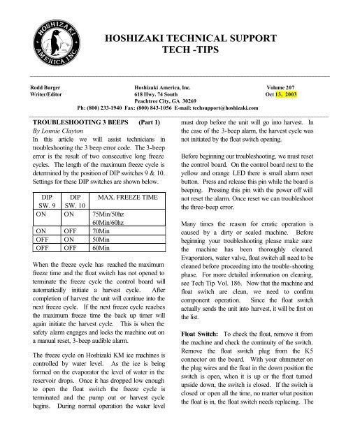
TROUBLESHOOTING 3 BEEPS (Part 1)<br />
By Lonnie Clayton<br />
In this article we will assist <strong>tech</strong>nicians in<br />
troubleshooting the 3 beep error code. The 3-beep<br />
error is the result of two consecutive long freeze<br />
cycles. The length of the maximum freeze cycle is<br />
determined by the position of DIP switches 9 & 10.<br />
Settings for these DIP switches are shown below.<br />
DIP DIP MAX. FREEZE TIME<br />
SW. 9 SW. 10<br />
ON ON 75Min/50hz<br />
60Min/60hz<br />
ON OFF 70Min<br />
OFF ON 50Min<br />
OFF OFF 60Min<br />
When the freeze cycle has reached the maximum<br />
freeze time and the float switch has not opened to<br />
terminate the freeze cycle the control board will<br />
automatically initiate a harvest cycle. After<br />
completion of harvest the unit will continue into the<br />
next freeze cycle. If the next freeze cycle reaches<br />
the maximum freeze time the back up timer will<br />
again initiate the harvest cycle. This is when the<br />
safety alarm engages and locks the machine out on<br />
a manual reset, 3-beep audible alarm.<br />
The freeze cycle on <strong>Hoshizaki</strong> KM ice machines is<br />
controlled by water level. As the ice is being<br />
formed on the evaporator the level of water in the<br />
reservoir drops. Once it has dropped low enough<br />
to open the float switch the freeze cycle is<br />
terminated and the pump out or harvest cycle<br />
begins. During normal operation the water level<br />
must drop before the unit will go into harvest. In<br />
the case of the 3-beep alarm, the harvest cycle was<br />
not initiated by the float switch opening.<br />
Before beginning our troubleshooting, we must reset<br />
the control board. On the control board next to the<br />
yellow and orange LED there is small alarm reset<br />
button. Press and release this pin while the board is<br />
beeping. Pressing this pin with the power off will<br />
not reset the alarm. Once reset we can troubleshoot<br />
the three-beep error.<br />
Many times the reason for erratic operation is<br />
caused by a dirty or scaled machine. Before<br />
beginning your troubleshooting please make sure<br />
the machine has been thoroughly cleaned.<br />
Evaporators, water valve, float switch all need to be<br />
cleaned before proceeding into the trouble-shooting<br />
phase. For more detailed information on cleaning,<br />
see Tech Tip Vol. 186. Now that the machine and<br />
float switch are clean, we need to confirm<br />
component operation. Since the float switch<br />
actually sends the unit into harvest, it will be first on<br />
the list.<br />
Float Switch: To check the float, remove it from<br />
the machine and check the continuity of the switch.<br />
Remove the float switch plug from the K5<br />
connector on the board. With your ohmmeter on<br />
the plug wires and the float in the down position the<br />
switch is open, when it is up or the float turned<br />
upside down, the switch is closed. If the switch is<br />
closed or open all the time, no matter what position<br />
the float is in, the float switch needs replacing. The
number one cause for failure of float switches is<br />
scale.<br />
Water inlet Valve: This valve should be<br />
completely closed during our freeze cycle. To<br />
check this part pull the small hose off the water<br />
valve outlet going to the evaporator section. No<br />
water should be flowing from this valve during the<br />
freeze cycle. If water is by passing the valve,<br />
disassemble and clean/replace if necessary. See<br />
SB01-0009 for more info on water valve rebuilding.<br />
Control Board: Test the control board, float<br />
switch operation. After 5 minutes of freeze drain<br />
the water out of the reservoir. When the water has<br />
drained the float switch will open and the control<br />
board will terminate the freeze cycle and initiate the<br />
harvest or pump out cycle. If the freeze cycle does<br />
not terminate, remove the K5 connection to the<br />
board. If the unit still does not go into harvest, the<br />
control board is defective.<br />
Note: It is important to confirm what portion of the<br />
cycle the board is in. With “E” style control boards<br />
this can be done by confirming which LED lights are<br />
energized. When the board is in harvest, LED 1, 4<br />
and 2 should be energized. When the control<br />
board goes into the freeze cycle LED 1 will<br />
energize.<br />
If you are working on a unit with an earlier control<br />
board this check can be done using a volt meter.<br />
When the unit is in harvest you will read 115 VAC<br />
at the pink wire and when it is in freeze the black<br />
and red wires will be energized.<br />
Water pump: The water pump itself can be easily<br />
tested by putting the unit in wash. We must<br />
however also confirm the operation of the water<br />
pump in conjunction with the control board.<br />
When the unit begins the freeze cycle, the water<br />
pump and condenser fan motor should energize on<br />
self-contained units. (Remote units the condenser<br />
fan starts with the compressor.) If the water pump<br />
fails to come on check voltage from the control<br />
board K1 connector, red wire, we should see 110<br />
volts. If not, it is a good idea to verify that the<br />
board is actually in the “freeze” cycle. See note<br />
above to confirm cycle. If we find red with power<br />
at the control board and the pump is still not<br />
running, next check the toggle switch.<br />
Toggle Switch: Here you will find two red wires.<br />
Without removing them from the toggle switch<br />
check each one to ground for 110 volts, if one has<br />
power and the other does not, the toggle switch<br />
contacts are open. If you temporarily jump these<br />
wires together, the pump should energize. If we find<br />
voltage on both, check voltage at the pump itself,<br />
we should read 110-115VAC between black and<br />
red at the Molex connector. If we have voltage<br />
there, the pump is suspect.<br />
Be sure to look for the November Tech Tip Vol.<br />
208 for the continuation of this article with<br />
information on trouble shooting refrigeration related<br />
components.<br />
REMINDER!!<br />
The <strong>Hoshizaki</strong> Technical Support Department is<br />
sponsoring two Advanced Training classes at the<br />
factory in Peachtree City, GA. These are two-day<br />
classes and consist of detailed training on all model<br />
lines, factory tour, along with a limited amount of<br />
hands on trouble shooting. See the schedule below<br />
for dates. October 21-22<br />
December 9-10<br />
For more information on these classes, please call<br />
1-800-233-1940 ext. 358.<br />
COMING NEXT MONTH…<br />
1. 3 Beep errors continued…<br />
Volume 207 page 2


