Field TZIDC-110 Electro-Pneumatic Positioner
Field TZIDC-110 Electro-Pneumatic Positioner
Field TZIDC-110 Electro-Pneumatic Positioner

You also want an ePaper? Increase the reach of your titles
YUMPU automatically turns print PDFs into web optimized ePapers that Google loves.
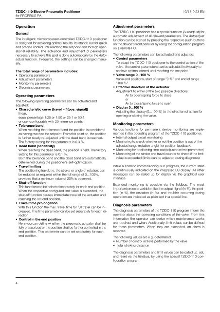
<strong>TZIDC</strong>-<strong>110</strong> <strong>Electro</strong>-<strong>Pneumatic</strong> <strong>Positioner</strong><br />
for PROFIBUS PA<br />
10/18-0.23 EN<br />
Operation<br />
General<br />
The intelligent microprocessor-controlled <strong>TZIDC</strong>-<strong>110</strong> positioner<br />
is designed for achieving optimal results. Its stands out for quick<br />
and precise control until reaching the set point and for high operational<br />
reliability. The activation and adjustment of parameters<br />
necessary to achieve this goal is done automatically by the Autoadjust<br />
function. If required, the settings can be changed manually.<br />
The total range of parameters includes:<br />
• Operating parameters<br />
• Adjustment parameters<br />
• Monitoring parameters<br />
• Diagnosis parameters<br />
Operating parameters<br />
The following operating parameters can be activated and<br />
adjusted:<br />
• Characteristic curve (travel = f {pos. signal})<br />
linear,<br />
equal percentage 1:25 or 1:50 or 25:1 or 50:1,<br />
or user-configurable with 20 reference points<br />
• Tolerance band<br />
When reaching the tolerance band the position is considered<br />
as having reached the setpoint. From this point on, the position<br />
is further slowly re-adjusted until the dead band is reached.<br />
The factory setting for this parameter is 0.3 %.<br />
• Dead band (sensitivity)<br />
When reaching the dead band, the position is held. The factory<br />
setting for this parameter is 0.1 %.<br />
Both the tolerance band and the dead band are automatically<br />
determined during the positioner’s self-optimization.<br />
• Travel limiting<br />
The positioning travel, i.e. the stroke or angle of rotation, can<br />
be reduced as required within the full range of 0...100%,<br />
provided that a minimum value of 20% is observed.<br />
• Shut-off function<br />
This function can be selected separately for each end position.<br />
When the respective configured limit value is exceeded, the<br />
shut-off function causes immediate travel of the actuator until<br />
reaching the set end position.<br />
• Travel time prolongation<br />
With this function the max. travel time for full travel can be increased.<br />
This time parameter can be set separately for each direction<br />
• Control in the end position<br />
Here you can define whether the pneumatic actuator shall be<br />
fully pressurized or the position shall be further controlled in the<br />
end position. This parameter can be set separately for each<br />
end position.<br />
Adjustment parameters<br />
The <strong>TZIDC</strong>-<strong>110</strong> positioner has a special function (Autoadjust) for<br />
automatic adjustment of all relevant parameters. The Autoadjust<br />
function can be started by pressing the respective push-buttons<br />
on the device’s front panel or by using the configuration program<br />
on a remote PC.<br />
The following parameters can be activated and adjusted:<br />
• Control parameters<br />
To adapt the <strong>TZIDC</strong>-<strong>110</strong> positioner to the control action of the<br />
valve, the control parameters can be adjusted individually to<br />
achieve optimal control until reaching the set point.<br />
• Valve range 0...100 %<br />
Valve end positions, start of range "0 %” and end of range<br />
"100 %".<br />
• Effective direction of the actuator<br />
Adjustment to either of the two possible directions:<br />
Air to open/spring force to close<br />
or<br />
Air to close/spring force to open<br />
• Display 0...100 %<br />
Adjusting the display (0...100 %) to the direction of action for<br />
opening or closing the valve.<br />
Monitoring parameters<br />
Various functions for permanent device monitoring are implemented<br />
in the operating program of the <strong>TZIDC</strong>-<strong>110</strong> positioner:<br />
• Internal output circuit monitoring<br />
• Monitoring to check whether or not the position is out of the<br />
adjusted range (rotation angle) for position feedback.<br />
• Monitoring for positioning time-out (adjustable time parameter)<br />
• Monitoring of the stroke and travel counter to check if the limit<br />
value is exceeded (limits can be adjusted during diagnosis)<br />
While automatic commissioning is in progress, the current state<br />
is continuously indicated on the integrated LC display. All other<br />
messages can be called up for display via the graphical user<br />
interface.<br />
Extended monitoring is possible via the fieldbus. The most<br />
important process variables like the output signal (in %), the position<br />
(in %), the deviation (in %), and troubles occurring during<br />
operation are indicated as plain text in a special line.<br />
Diagnosis parameters<br />
The diagnosis parameters of the <strong>TZIDC</strong>-<strong>110</strong> program inform the<br />
operator about the operating conditions of the valve. From this<br />
information the operator can derive which maintenance works<br />
are required, and when. Additionally, limit values can be defined<br />
for these parameters. When they are exceeded, an alarm is<br />
reported.<br />
The following values are e.g. determined:<br />
• Number of control actions performed by the valve<br />
• Total stroking distance<br />
The diagnosis parameters and limit values can be called up, set,<br />
and reset via the fieldbus, by using the special <strong>TZIDC</strong>-<strong>110</strong> configuration<br />
program.<br />
4