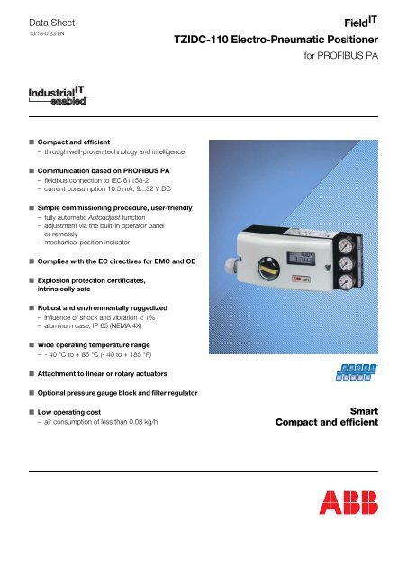
Field TZIDC-110 Electro-Pneumatic Positioner
Field TZIDC-110 Electro-Pneumatic Positioner
Field TZIDC-110 Electro-Pneumatic Positioner
Create successful ePaper yourself
Turn your PDF publications into a flip-book with our unique Google optimized e-Paper software.
Data Sheet<br />
10/18-0.23 EN<br />
<strong>Field</strong>IT<br />
<strong>TZIDC</strong>-<strong>110</strong> <strong>Electro</strong>-<strong>Pneumatic</strong> <strong>Positioner</strong><br />
for PROFIBUS PA<br />
■ Compact and efficient<br />
– through well-proven technology and intelligence<br />
■ Communication based on PROFIBUS PA<br />
– fieldbus connection to IEC 61158-2<br />
– current consumption 10.5 mA, 9...32 V DC<br />
■ Simple commissioning procedure, user-friendly<br />
– fully automatic Autoadjust function<br />
– adjustment via the built-in operator panel<br />
or remotely<br />
– mechanical position indicator<br />
■ Complies with the EC directives for EMC and CE<br />
■ Explosion protection certificates,<br />
intrinsically safe<br />
■ Robust and environmentally ruggedized<br />
– influence of shock and vibration < 1%<br />
– aluminum case, IP 65 (NEMA 4X)<br />
■ Wide operating temperature range<br />
– - 40 °C to + 85 °C (- 40 to + 185 °F)<br />
■ Attachment to linear or rotary actuators<br />
P R O F I<br />
PROCESS FIELD BUS<br />
B U S<br />
®<br />
■ Optional pressure gauge block and filter regulator<br />
■ Low operating cost<br />
– air consumption of less than 0.03 kg/h<br />
Smart<br />
Compact and efficient
<strong>TZIDC</strong>-<strong>110</strong> <strong>Electro</strong>-<strong>Pneumatic</strong> <strong>Positioner</strong><br />
for PROFIBUS PA<br />
10/18-0.23 EN<br />
Concept<br />
The <strong>TZIDC</strong>-<strong>110</strong> positioner is an intelligent and electronically configurable<br />
instrument with communication capabilities, mounting<br />
to pneumatic actuators. The <strong>TZIDC</strong>-<strong>110</strong> stands out for a small<br />
and compact design, a modular construction, and an excellent<br />
cost-performance ratio.<br />
The functional heart of the <strong>TZIDC</strong>-<strong>110</strong> positioner is its microprocessor-controlled<br />
CPU where the operating system is running.<br />
The position feedback signal is polled with a sampling rate of<br />
20 ms and an A/D resolution of 16,000 steps. This ensures a<br />
rapid and high-precision signal processing for the input and the<br />
position feedback. The power for the CPU is derived from the<br />
bus.<br />
The operating program includes functions for fully automatic<br />
adjustment in the commissioning phase. These functions provide<br />
for optimal control of the position to minimize control deviation.<br />
The pneumatic actuator is driven by an I/P module with subsequent<br />
3/3-way valve. The electrical positioning signal from the<br />
CPU is proportionally converted into a pneumatic signal which, in<br />
turn, adjusts the 3/3-way valve. The cross-sectional area of the<br />
valve air channels for filling the actuator with air or evacuating air<br />
from it is changed in proportion with the adjustment. When<br />
reaching the set point, the 3/3-way valve is closed in center position.<br />
The positioner has an operating panel consisting of a 2-line LCD<br />
and 4 push-buttons. The operating panel has the perfect design<br />
for optimal local configuration, commissioning, and operational<br />
monitoring. Alternatively, the <strong>TZIDC</strong>-<strong>110</strong> can be configured,<br />
commissioned and monitored via the fieldbus, by using the<br />
appropriate configuration program.<br />
The modular design of the positioner allows you to add further<br />
functionality at a later time. Assembly kits for mechanical position<br />
indication for digital position feedback using proximity switches<br />
or 24 V microswitches are available. Additionally, the plug-in<br />
module for the shutdown function is available.<br />
Various <strong>TZIDC</strong>-<strong>110</strong> features ensure safe valve operation on site:<br />
• Compliance with the EMC Directive<br />
• Robust aluminum case, protection IP 65 (NEMA 4X)<br />
• High resistance to shock and vibration up to 10 g<br />
• Operational reliability through permanent internal monitoring<br />
• Message generation<br />
• Operation at ambient temperatures of - 40 to + 85 °C<br />
(- 40 to + 185 °F)<br />
Options<br />
Microprocessor<br />
Bus connector<br />
Nonvolatile<br />
memory<br />
CPU<br />
Plug-in module for<br />
safety shutdown<br />
(forced decompression)<br />
24 V DC<br />
Optocoupler<br />
(Shutdown function)<br />
Mechanical<br />
position indicator<br />
Air supply<br />
1.4...6 bar<br />
Outgoing air<br />
I/P module<br />
with 3/3-way valve<br />
Position<br />
Position feedback<br />
Min.<br />
Max.<br />
or<br />
24V microswitch<br />
min./max. position<br />
Fig.1:<br />
<strong>TZIDC</strong>-<strong>110</strong> schematic diagram<br />
2
<strong>TZIDC</strong>-<strong>110</strong> <strong>Electro</strong>-<strong>Pneumatic</strong> <strong>Positioner</strong><br />
for PROFIBUS PA<br />
10/18-0.23 EN<br />
Mounting<br />
To linear actuators in accordance with the standard<br />
Lateral attachment is in accordance with DIN/IEC 534 (lateral<br />
attachment to NAMUR). The required attachment kit is a complete<br />
set of attachment material, but does not include the<br />
screwed pipe connections and air pipes.<br />
To rotary actuators in accordance with the standard<br />
Attachment to rotary actuators is in accordance with VDI/VDE<br />
3845. The attachment kit contains the adapter for coupling the<br />
positioner feedback shaft to the actuator shaft, and mounting<br />
brackets for mounting the positioner to the actuator. Screwed<br />
pipe connections and air pipes are not included in the kit and<br />
have to be provided by the customer.<br />
Integral mounting to control valves<br />
The <strong>TZIDC</strong>-<strong>110</strong> positioner is ready for integral mounting. The<br />
appropriate threaded holes are available at the positioner’s back.<br />
The benefit of this design is that the point for mechanical stroke<br />
measurement is inside the yoke and, thus, protected by it. No<br />
external tubing is required, since the air flow from the positioner<br />
to the actuator is guided through an internal channel bore.<br />
Special actuator-specific mounting<br />
In addition to the mounting methods described above, there are<br />
special actuator-specific attachments.<br />
Please contact us for details.<br />
Fig. 2: Mounting to linear actuators to DIN/IEC 534<br />
Fig. 4: Mounting to rotary actuators to VDI/VDE 3845<br />
Fig. 3:<br />
Integral mounting to control valves<br />
Fig. 5:<br />
Integral mounting to control valves by using an adapter panel<br />
3
<strong>TZIDC</strong>-<strong>110</strong> <strong>Electro</strong>-<strong>Pneumatic</strong> <strong>Positioner</strong><br />
for PROFIBUS PA<br />
10/18-0.23 EN<br />
Operation<br />
General<br />
The intelligent microprocessor-controlled <strong>TZIDC</strong>-<strong>110</strong> positioner<br />
is designed for achieving optimal results. Its stands out for quick<br />
and precise control until reaching the set point and for high operational<br />
reliability. The activation and adjustment of parameters<br />
necessary to achieve this goal is done automatically by the Autoadjust<br />
function. If required, the settings can be changed manually.<br />
The total range of parameters includes:<br />
• Operating parameters<br />
• Adjustment parameters<br />
• Monitoring parameters<br />
• Diagnosis parameters<br />
Operating parameters<br />
The following operating parameters can be activated and<br />
adjusted:<br />
• Characteristic curve (travel = f {pos. signal})<br />
linear,<br />
equal percentage 1:25 or 1:50 or 25:1 or 50:1,<br />
or user-configurable with 20 reference points<br />
• Tolerance band<br />
When reaching the tolerance band the position is considered<br />
as having reached the setpoint. From this point on, the position<br />
is further slowly re-adjusted until the dead band is reached.<br />
The factory setting for this parameter is 0.3 %.<br />
• Dead band (sensitivity)<br />
When reaching the dead band, the position is held. The factory<br />
setting for this parameter is 0.1 %.<br />
Both the tolerance band and the dead band are automatically<br />
determined during the positioner’s self-optimization.<br />
• Travel limiting<br />
The positioning travel, i.e. the stroke or angle of rotation, can<br />
be reduced as required within the full range of 0...100%,<br />
provided that a minimum value of 20% is observed.<br />
• Shut-off function<br />
This function can be selected separately for each end position.<br />
When the respective configured limit value is exceeded, the<br />
shut-off function causes immediate travel of the actuator until<br />
reaching the set end position.<br />
• Travel time prolongation<br />
With this function the max. travel time for full travel can be increased.<br />
This time parameter can be set separately for each direction<br />
• Control in the end position<br />
Here you can define whether the pneumatic actuator shall be<br />
fully pressurized or the position shall be further controlled in the<br />
end position. This parameter can be set separately for each<br />
end position.<br />
Adjustment parameters<br />
The <strong>TZIDC</strong>-<strong>110</strong> positioner has a special function (Autoadjust) for<br />
automatic adjustment of all relevant parameters. The Autoadjust<br />
function can be started by pressing the respective push-buttons<br />
on the device’s front panel or by using the configuration program<br />
on a remote PC.<br />
The following parameters can be activated and adjusted:<br />
• Control parameters<br />
To adapt the <strong>TZIDC</strong>-<strong>110</strong> positioner to the control action of the<br />
valve, the control parameters can be adjusted individually to<br />
achieve optimal control until reaching the set point.<br />
• Valve range 0...100 %<br />
Valve end positions, start of range "0 %” and end of range<br />
"100 %".<br />
• Effective direction of the actuator<br />
Adjustment to either of the two possible directions:<br />
Air to open/spring force to close<br />
or<br />
Air to close/spring force to open<br />
• Display 0...100 %<br />
Adjusting the display (0...100 %) to the direction of action for<br />
opening or closing the valve.<br />
Monitoring parameters<br />
Various functions for permanent device monitoring are implemented<br />
in the operating program of the <strong>TZIDC</strong>-<strong>110</strong> positioner:<br />
• Internal output circuit monitoring<br />
• Monitoring to check whether or not the position is out of the<br />
adjusted range (rotation angle) for position feedback.<br />
• Monitoring for positioning time-out (adjustable time parameter)<br />
• Monitoring of the stroke and travel counter to check if the limit<br />
value is exceeded (limits can be adjusted during diagnosis)<br />
While automatic commissioning is in progress, the current state<br />
is continuously indicated on the integrated LC display. All other<br />
messages can be called up for display via the graphical user<br />
interface.<br />
Extended monitoring is possible via the fieldbus. The most<br />
important process variables like the output signal (in %), the position<br />
(in %), the deviation (in %), and troubles occurring during<br />
operation are indicated as plain text in a special line.<br />
Diagnosis parameters<br />
The diagnosis parameters of the <strong>TZIDC</strong>-<strong>110</strong> program inform the<br />
operator about the operating conditions of the valve. From this<br />
information the operator can derive which maintenance works<br />
are required, and when. Additionally, limit values can be defined<br />
for these parameters. When they are exceeded, an alarm is<br />
reported.<br />
The following values are e.g. determined:<br />
• Number of control actions performed by the valve<br />
• Total stroking distance<br />
The diagnosis parameters and limit values can be called up, set,<br />
and reset via the fieldbus, by using the special <strong>TZIDC</strong>-<strong>110</strong> configuration<br />
program.<br />
4
<strong>TZIDC</strong>-<strong>110</strong> <strong>Electro</strong>-<strong>Pneumatic</strong> <strong>Positioner</strong><br />
for PROFIBUS PA<br />
10/18-0.23 EN<br />
Operator panel<br />
The <strong>TZIDC</strong>-<strong>110</strong> positioner’s operator panel allows for<br />
• monitoring<br />
•manual control<br />
• <strong>TZIDC</strong>-<strong>110</strong> configuration<br />
• fully automatic commissioning<br />
Operation<br />
The panel’s four push buttons (see illustration) are used for<br />
selecting the individual operating levels, parameterizing the<br />
device, and saving the settings. In addition to the already known<br />
operating functions there is a special feature: a simplified autoadjustment<br />
routine can be started easily through only few operator<br />
actions, and without knowing parameterization details.<br />
When the positioner is changed over from a linear to a rotary<br />
actuator, the zero position of the display is changed automatically.<br />
As a result, 0% is indicated in the display for a valve that is<br />
closed by turning clockwise.<br />
Display<br />
The information indicated by the 2-digit LC display is permanently<br />
updated and adapted during operation, to inform the<br />
operator in an optimal way.<br />
In bus mode (REMOTE), the following <strong>TZIDC</strong>-<strong>110</strong> data can be<br />
called up by pressing the push-buttons briefly:<br />
Enter<br />
Software revision<br />
Up arrow For cyclic communication:<br />
Setpoint (%) and setpoint state (decimal)<br />
For acyclic communication:<br />
communication state<br />
Down arrow Operating mode on the bus and<br />
address in the device<br />
conf<br />
°C<br />
%<br />
mA<br />
ENTER<br />
MODE<br />
Fig. 6:<br />
<strong>TZIDC</strong>-<strong>110</strong> operating elements<br />
Configuration program<br />
General<br />
The graphical user interface for the <strong>TZIDC</strong>-<strong>110</strong> positioner is<br />
based on the FDT/DTM technology (FDT 0.98-1) and can be<br />
integrated in an open control system or loaded into a PC with the<br />
configuration program SMART VISION ® . With this you can use<br />
the same user interface in the commissioning phase, during<br />
operation, and for service tasks for monitoring the device, setting<br />
parameters, and uploading data.<br />
In all cases the communication is realized via the fieldbus connection.<br />
In accordance with the PROFIBUS conventions it is possible<br />
to read data during cyclic data exchange (AUT, MAN or<br />
RCAS mode) and write data in the O/S (Out of Service) mode.<br />
Newly set parameters are saved in the non-volatile memory<br />
directly upon the download into the device, and are immediately<br />
active.<br />
Fig. 7:<br />
Direct link to a PC/laptop<br />
5
<strong>TZIDC</strong>-<strong>110</strong> <strong>Electro</strong>-<strong>Pneumatic</strong> <strong>Positioner</strong><br />
for PROFIBUS PA<br />
10/18-0.23 EN<br />
Technical data<br />
Communication<br />
Profiles<br />
Profibus PA Profile for Process Control Devices<br />
<strong>Electro</strong>-<strong>Pneumatic</strong> Actuators V3.0<br />
Block types<br />
1 AO Function Block, 1 Transducer Block, 1 Physical Block<br />
Physical layer<br />
Compliant to the standard IEC 61158-2<br />
Communication speed<br />
31.25 Kbit/s<br />
Operating voltage<br />
Bus-powered: 9.0 V DC - 32.0 V DC<br />
Max withstand voltage<br />
35 V DC<br />
Current consumption<br />
10.5 mA<br />
Fault current<br />
15 mA (10.5 mA + 4.5 mA)<br />
Name value<br />
Physical device tag<br />
TZID-C<strong>110</strong><br />
PNO ID number<br />
0x0639<br />
Device ID<br />
0X3200028xyz<br />
Device address<br />
Between 0 and 126, default node address 126<br />
Output<br />
Range<br />
0...6 bar (0...90 psi)<br />
Air capacity<br />
at supply pressure of 1.4 bar (20 psi):<br />
5.0 kg/h = 3.9 Nm 3 /h = 2.3 scfm<br />
at supply pressure of 6 bar (90 psi)<br />
13 kg/h = 10 Nm 3 /h = 6.0 scfm<br />
(Booster for increasing air capacity on request)<br />
Function<br />
for single or double acting actuators, air is vented from actuator or<br />
actuator is blocked in case of an electrical power failure<br />
Shut-off value<br />
When the setpoint exceeds or falls below the defined limit value, the<br />
actuator immediately moves to the 0% or 100 % position.<br />
Travel<br />
Angle of rotation<br />
Used range 25...120 ° (rotary actuators, optionally 270°)<br />
25...60 ° (linear actuators)<br />
Travel time prolongation<br />
Range 0...200 seconds, individually configurable for each direction<br />
Dead band time limit<br />
Range 0...200 seconds (monitoring parameter for control until the<br />
deviation is within the tolerance band)<br />
Stroke limiting<br />
Min. and max limits,<br />
freely configurable within 0...100% of total travel (> 20 %)<br />
Air supply<br />
Instrument air<br />
Free of oil, water and dust to DIN/ISO 8573-1<br />
Pollution and oil contents according to Class 3<br />
(purity: max. particle size 5 µm, max. particle density 5mg/m 3 ,<br />
oil contents: max. concentration 1 mg/m 3 ;<br />
dew point at least 10 °C below operating temperature)<br />
Supply pressure<br />
1.4...6 bar (20...90 psi)<br />
Caution: Do not exceed the max. operating pressure of the actuator!<br />
Air consumption<br />
< 0.03 kg/h (0.08 scfm) (independent of supply pressure)<br />
Transmission data and influences<br />
Action (output signal or pressure in the actuator)<br />
Direct:<br />
Increasing signal 0...100 mA<br />
Increas. pressure OUT1 in the actuator<br />
Reverse:<br />
Increasing signal 0...100 mA<br />
Decreas. pressure OUT1 in the actuator<br />
Characteristic curve (travel = f {signal})<br />
Linear, equal percentage 1:25 or 1:50 or 25:1 or 50:1<br />
and freely configurable with 20 reference points<br />
Characteristic deviation<br />
< 0.5 %<br />
Tolerance band<br />
0.3...10 %, adjustable<br />
Dead band<br />
0.1... 5 %, adjustable<br />
Resolution (A/D conversion)<br />
16,000 steps<br />
Sample rate<br />
20 milliseconds<br />
Influence of ambient temperature<br />
< 0.5 % for every 10 °C change in temperature<br />
Influence of vibration<br />
≤ +/-1 % up to 10 g and 80 Hz<br />
Seismic requirements<br />
Meets requirements of DIN/IEC 68-3-3 Class III for strong and<br />
strongest earthquakes<br />
Influence of mounting orientation<br />
No effect<br />
Meets the following requirements<br />
EMC Directive 89/336/EEC as of May 1989<br />
EC Directive for the CE conformity marking<br />
6
<strong>TZIDC</strong>-<strong>110</strong> <strong>Electro</strong>-<strong>Pneumatic</strong> <strong>Positioner</strong><br />
for PROFIBUS PA<br />
10/18-0.23 EN<br />
Environmental capabilities<br />
Ambient temperature<br />
-40 to +85 °C (- 40 to + 185 °F)<br />
for operation, storage and transport<br />
Relative humidity<br />
Operational (with closed housing and air supply switched on):<br />
100 %, condensation permissible<br />
Transport and storage:<br />
75 % (annual average), non-condensing<br />
Case<br />
Material/protection<br />
Aluminum, protection IP 65 (NEMA 4X)<br />
Surface/Color<br />
<strong>Electro</strong>static dipping varnish with expoxy resin, stove-enamelled<br />
Bottom part of case varnished black, RAL 9005, matt,<br />
Cover white aluminum, RAL 9006<br />
Electrical connections<br />
Screw terminals<br />
max. 1.0 mm 2 for options, max. 2.5 mm 2 for bus connection<br />
Caution: Do not expose the terminals to strain!<br />
Cable entry<br />
2 threads Pg. 13.5, 1/2-14 NPT or M20x1.5<br />
for cable diameter 6...12 mm<br />
1 with cable gland and 1 with pipe plug<br />
<strong>Pneumatic</strong> connections<br />
Threads G 1/4 or 1/4-18 NPT<br />
Weight<br />
1.7 kg<br />
Mounting orientation<br />
any orientation allowed<br />
Dimensions<br />
see dimensional drawings<br />
Explosion protection<br />
FM/CSA<br />
(pending)<br />
ATEX<br />
II 2G EEx ia II C T6<br />
Type examination certificate TÜV 02 ATEX 1831 X<br />
Type:<br />
Intrins. safe equipment<br />
Device class:<br />
II 2G (EEx ia IIC)<br />
Temperature class: T4, T5, T6<br />
Permissible<br />
ambient temperature: T4: -40 °C ≤ T amb ≤ 85 °C<br />
T5: -40 °C ≤ T amb ≤ 55 °C<br />
T6: -40 °C ≤ T amb ≤ 40 °C<br />
ATEX<br />
II 3G EEx n A II T6<br />
Type examination certificate TÜV 02 ATEX 1943 X<br />
Type:<br />
Explosion-proof equipment<br />
for zone 2<br />
Device class:<br />
II 3G (EEx n A II)<br />
Temperature class: T4, T5, T6<br />
Permissible<br />
ambient temperature: T4: -40 °C ≤ T amb ≤ 85 °C<br />
T5: -40 °C ≤ T amb ≤ 65 °C<br />
T6: -40 °C ≤ T amb ≤ 50 °C<br />
Signal current circuit for Profibus PA, only for connection to a certified<br />
intrinsically safe circuit (e.g. FISCO power unit or barrier)<br />
with the following max. values:<br />
FISCO<br />
ia/ib<br />
for group<br />
IIB/IIC<br />
FISCO<br />
ia/ib<br />
for group IIB/IIC<br />
Barrier or<br />
power supply unit<br />
ia/ib<br />
for group IIB/IIC<br />
Vi = 17.5 V Vi = 17.5 V Vi = 24 V<br />
Ii = 380 mA Ii = 360 mA Ii = 250 mA<br />
Pi = 5.32 W Pi = 2.52 W Pi = 1.2 W<br />
rectangular trapezoidal linear<br />
7
<strong>TZIDC</strong>-<strong>110</strong> <strong>Electro</strong>-<strong>Pneumatic</strong> <strong>Positioner</strong><br />
for PROFIBUS PA<br />
10/18-0.23 EN<br />
Options<br />
Module for the shutdown function<br />
Supply voltage<br />
V min = 20 V, V max = 30 V<br />
Safe pos. is activated when V < 5 V<br />
AK approval AK 4 to DIN V 19250<br />
Test report No.<br />
101/S01/148<br />
Explosion protection EEx ia IIC<br />
In case of a 24 V DC power failure, the positioner can let the valve move<br />
to the safe position by depressurizing the actuator independently of the<br />
processor. To achieve this, the I/P module power supply is separated by<br />
an optocoupler. Both the communication and feedback are still active,<br />
since the positioner is powered via the bus line. The shutdown input is<br />
electrically isolated from the control signal.<br />
Due to the shutdown function no additional solenoid valves are required.<br />
It has a safety certificate from TÜV Rheinland in accordance with AK4.<br />
The plug-in module also has an Ex certificate for use in intrinsically safe<br />
current circuits.<br />
Mechanical position indicator<br />
Indicator disk<br />
Cover with transparent dome<br />
Symbol stickers<br />
Extension for the feedback shaft<br />
Digital position feedback with proximity switches*<br />
2 proximity switches for min. and max. position<br />
(position adjustable within range of 0...100%)<br />
Current circuit to DIN 19234<br />
Supply voltage 5...11 V DC<br />
Control current < 1 mA = switching state logical “0“<br />
Control current > 3 mA = switching state logical “1“<br />
(works independently of the software and the electronics of the<br />
positioner)<br />
Accessories<br />
Mounting material<br />
Attachment kit for linear actuators to DIN/IEC 534<br />
(lateral attachment to NAMUR)<br />
Attachment kit for rotary actuators to VDI/VDE 3845<br />
Attachment kit for integral mounting<br />
Attachment kit for actuator-specific attachment on request<br />
Pressure gauge block<br />
With pressure gauges for supply and output pressure,<br />
Pressure gauges with plastic case ∅ 28 mm,<br />
with connection block made of aluminum, varnished black<br />
inclusive of mounting material for attachment to <strong>TZIDC</strong>-<strong>110</strong>.<br />
Filter regulator<br />
All metal version, brass varnished black<br />
Bronze filter element, 40 µm, with condensate drain<br />
Max. pre-pressure 16 bar, output adjustable to 1.4...6 bar<br />
PC software for remote configuration and operation<br />
SMART VISION ® ‚ (standard) as CD-ROM<br />
DTM for operation in an FDT environment<br />
see data sheet 10/63-1.20<br />
Adapter for bus communication<br />
see data sheet 10/63-6.41<br />
Spare parts kit<br />
Direction of action (logical state)<br />
Proximity switch<br />
Position<br />
< Min. > Min. < Max. > Max.<br />
SJ2-SN (NC) 0 1 1 0<br />
SJ2-S1N (NO) 1 0 0 1<br />
Digital position feedback with 24 V microswitches*<br />
Two 24 V DC/AC microswitches for the min. and max. position.<br />
Switching points adjustable between 0 and 100 %<br />
Not approved for use in the hazardous area!<br />
Voltage<br />
max. 24 V AC / DC<br />
Current load<br />
max. 2 A<br />
Contact surface<br />
10 µm Gold (AU)<br />
* The “digital position feedback“ option is directly actuated by the rotating shaft of<br />
the positioner and can only be used together with the mechanical position indicator<br />
described above.<br />
8
-<br />
<strong>TZIDC</strong>-<strong>110</strong> <strong>Electro</strong>-<strong>Pneumatic</strong> <strong>Positioner</strong><br />
for PROFIBUS PA<br />
10/18-0.23 EN<br />
Wiring diagrams<br />
1. Not used<br />
2. Service switch for the plug-in module with shutdown function<br />
3. Terminals for the plug-in module for the shutdown function<br />
4. Kit for digital position feedback, either proximity switches<br />
or 24 V microswitch (first connector)<br />
5. Kit for digital position feedback, either proximity switches or<br />
24 V microswitch (second connector)<br />
6. Bus terminals<br />
7. Enclosure ground<br />
1<br />
2<br />
3<br />
Off1<br />
On<br />
Off2<br />
+85-86<br />
+41 -42<br />
+51 -52<br />
Limit 1 Limit 2<br />
4<br />
5<br />
(11) (12)<br />
+ -<br />
6<br />
7<br />
Fig. 8:<br />
Electrical connections<br />
Kit for digital position feedback<br />
24 V Microswitch<br />
41 42 43<br />
51 52 53<br />
Limit 2<br />
Limit 1<br />
Input<br />
NO contact<br />
NC contact<br />
Input<br />
NO contact<br />
NC contact<br />
Kit for digital position feedback<br />
Pepperl & Fuchs proximity switches<br />
Plug-in module for shutdown function<br />
24 V<br />
+85 -86<br />
+41 -42<br />
+51 -52<br />
Limit 2<br />
Limit 1<br />
Limit 2<br />
Limit 1<br />
Basic model<br />
+<br />
(11) (12)<br />
Bus terminals<br />
Grounding screw<br />
Fig. 9:<br />
Terminal assignment<br />
9
<strong>TZIDC</strong>-<strong>110</strong> <strong>Electro</strong>-<strong>Pneumatic</strong> <strong>Positioner</strong><br />
for PROFIBUS PA<br />
10/18-0.23 EN<br />
Dimensional drawings (all dimensions in mm)<br />
14.5<br />
Output:<br />
1<br />
<strong>Positioner</strong><br />
TZID-C<br />
Document 901047<br />
II 2G EEx ib IIC T6<br />
TÜV 98 ATEX 1370 X<br />
Ui, Ii, Pi, Ci, Li, Tamb<br />
see certificate<br />
CE 0032<br />
Made in Germany<br />
TZID-C<br />
Typ 18345-<br />
Softw.-Rev.<br />
Serial no.<br />
Serien Nr.<br />
Supply press.: 1.4...6bar<br />
Zuluftdruck:<br />
20...90psi<br />
Input: analog 4-20mA<br />
Eingang:<br />
CE<br />
Ausgang:<br />
single<br />
double<br />
einfachwirkend<br />
doppeltwirkend<br />
Loss of electr. supply:<br />
Stromlos:<br />
fail<br />
entlüftend<br />
fail<br />
blockierend<br />
Options: analog feedback<br />
electr. limit switch<br />
mech. limit switch<br />
FSK<br />
position indicator<br />
Fig.10:<br />
Top view<br />
168.5<br />
104.5<br />
60<br />
33.5<br />
25<br />
7<br />
89.5<br />
65<br />
2<br />
50<br />
45°<br />
<strong>110</strong>.75<br />
M5x0.5<br />
Air outputs<br />
for direct<br />
attachment<br />
23<br />
58<br />
50<br />
Fig.11:<br />
Front view and rear view<br />
92<br />
10<br />
M5<br />
18<br />
2<br />
14<br />
14<br />
28.5 28<br />
14<br />
9<br />
10<br />
29<br />
Fig. 12:<br />
Side view (from the left and from the right side)<br />
10
<strong>TZIDC</strong>-<strong>110</strong> <strong>Electro</strong>-<strong>Pneumatic</strong> <strong>Positioner</strong><br />
for PROFIBUS PA<br />
10/18-0.23 EN<br />
30 / 53<br />
25<br />
75<br />
45 - 75<br />
B*<br />
A*<br />
*) Dimensions A and B depend on rotary actuator size<br />
Fig. 13: Mounting to linear actuators to DIN/IEC 534 Fig. 14: Mounting to rotary actuators to VDI/VDE 3845<br />
40<br />
120<br />
TZID-C<br />
97<br />
Fig.15:<br />
<strong>Positioner</strong> <strong>TZIDC</strong>-<strong>110</strong> with pressure gauge block and filter regulator<br />
11
<strong>TZIDC</strong>-<strong>110</strong> <strong>Electro</strong>-<strong>Pneumatic</strong> <strong>Positioner</strong><br />
for PROFIBUS PA<br />
10/18-0.23 EN<br />
Ordering information<br />
Catalog No EUR Deliv. time<br />
<strong>TZIDC</strong>-<strong>110</strong> Intelligent <strong>Positioner</strong> V18346- 0 0<br />
electro-pneumatic, configurable<br />
with indicator and operator panel<br />
Case/Mounting<br />
Case made of aluminium, varnished, protection IP 65 (NEMA 4X)<br />
For mounting to linear actuators acc. to DIN/IEC 534 or to rotary<br />
actuators acc. to VDI/VDE 3845, also ready for integral mounting 1 902,00 4 wks.<br />
As above, but with mechanical position indicator 2 928,00 4 wks.<br />
For mounting to rotary actuators acc. to VDI/VDE 3845 with<br />
extended rotation angle up to 270° 5 980,00<br />
As above, but with mechanical position indicator 6 1006,00<br />
Note:<br />
Special mounting material as specified under<br />
"Accessories" is required<br />
Input/communication port<br />
Profibus PA 3 -<br />
Explosion protection<br />
without 0 -<br />
ATEX EEx ia IIC T6 1 47,00<br />
FM/CSA 2 47,00<br />
ATEX EEx n A II T6 4<br />
Explosion protection certificate upon special agreement (on request)<br />
Output/safe position (in case of an electrical power failure)<br />
Single acting, fail safe 1 -<br />
fail freeze 2 -<br />
Double acting, fail safe 4 95,00<br />
fail freeze 5 95,00<br />
Connections<br />
Cable: Thread Pg. 13.5 Air pipe: Thread G 1/4 1 -<br />
Cable: Thread 1/2-14 NPT Air pipe: Thread 1/4-18 NPT 2 -<br />
Cable: Thread Pg 13.5 Air pipe: Thread 1/4-18 NPT 3 -<br />
Cable: Thread M20 x 1,5 Air pipe: Thread M12 x 1 4 -<br />
Cable: Thread M20 x 1,5 Air pipe: Thread 1/4-18 NPT 5 -<br />
Cable: Thread M20 x 1,5 Air pipe: Thread G 1/4 6 -<br />
Option modules for analog or digital position feedback<br />
Without 0 -<br />
Plug-in module for shutdown module (temperature: -30°…+60°) 4 90,00<br />
Mechanical Kit for digital position feedback (option)<br />
Without 0 -<br />
Mechanical kit for digital feedback of minimum and maximum position 1)<br />
With proximity switches SJ2-SN (NC or logical 1) 1 216,00<br />
With proximity switches SJ2-S1N (NO or logical 0) 3 216,00<br />
With 24 V DC/AC microswitches (change-over contacts) 5 103,00<br />
1)<br />
only for model with mechanical position indicator Continued on the next page<br />
12
<strong>TZIDC</strong>-<strong>110</strong> <strong>Electro</strong>-<strong>Pneumatic</strong> <strong>Positioner</strong><br />
for PROFIBUS PA<br />
10/18-0.23 EN<br />
Ordering information (continued)<br />
Catalog No EUR Deliv. time<br />
<strong>TZIDC</strong>-<strong>110</strong> Intelligent <strong>Positioner</strong> V18346-<br />
electro-pneumatic, configurable<br />
with indicator and operator panel<br />
Design (varnish/coding)<br />
Standard 1 -<br />
Special version chemistry (details on request) E -<br />
As specified (on request)<br />
Device identification label<br />
incudes lettering (plain text, max. 16 letters)<br />
stainless steel 11.5 x 60 mm on requ.<br />
sticker 41 x 32 mm on requ.<br />
sticker 11 x 25 mm on requ.<br />
Note: The kit for digital position feedback (proximity switches) is identical for positioners<br />
with or without explosion protection.<br />
The 24V microswitches must not be used in hazardous areas.<br />
Accessories<br />
Catalog No EUR Deliv. time<br />
Mounting material and cost<br />
Attachment kit for linear actuators (lateral attachment to DIN/IEC 534 or Namur)<br />
Stroke 10... 35 mm 18391-7959125 58,00 1 wk.<br />
Stroke 20 ... 100 mm 18391-7959126 58,00 1 wk.<br />
Attachment kit for integral mounting to<br />
23/24 and 23/25 cont. valve DN 15 up to DN 100, stroke 10...35 mm 18391-7959106 42,00 1 wk.<br />
DN 125 up to DN 150, stroke 25...65 mm 18391-7959107 42,00 1 wk.<br />
23/26 control valve DN 25 up to DN 100, stroke 10...35 mm 18391-7959108 84,00 1 wk.<br />
DN 125 up to DN 162, stroke 25...65 mm 18391-7959109 84,00 1 wk.<br />
Attachment kit for rotary actuators (mounting to VDI/VDE 3845), consisting of<br />
a) Adapter (shaft coupler) 18391-7959<strong>110</strong> 37,00 1 wk.<br />
b) Mounting bracket, dimensions A/B = 80/20 mm 18391-0319603 63,00 1 wk.<br />
A/B = 80/30 mm 18391-0319604 63,00 1 wk.<br />
A/B = 130/30 mm 18391-0319605 63,00 1 wk.<br />
A/B = 130/50 mm 18391-0319606 63,00 2 wks.<br />
Mounting cost, material and adjustment<br />
for mounting to linear actuators to DIN/IEC 534<br />
or to rotary actuators to VDI/VDE 3845<br />
External tubing with Plastic tube 18391-0319628 58,00 2 wks.<br />
Copper pipe 18391-0319629 79,00 2 wks.<br />
Stainless steel pipe 18391-0319630 147,00 2 wks.<br />
for integral mounting to 23/24, 23/25 or 23/26 control valves<br />
Internal tubing 18391-0319627 48,00 2 wks.<br />
External tubing 1) with Copper pipe 18391-7959015 79,00 2 wks.<br />
Stainless steel pipe 18391-7959016 147,00 2 wks.<br />
1)<br />
External tubing only for 23/24 and 23/25 control valves with<br />
"air to close/spring to open" action, otherwise internal tubing only.<br />
13
<strong>TZIDC</strong>-<strong>110</strong> <strong>Electro</strong>-<strong>Pneumatic</strong> <strong>Positioner</strong><br />
for PROFIBUS PA<br />
10/18-0.23 EN<br />
Accessories<br />
Catalog No EUR Deliv. time<br />
Pressure gauge block<br />
Pressure gauge block, including attachment material<br />
for single acting <strong>TZIDC</strong>-<strong>110</strong>, with 2 pressure gauges Ø 28 mm<br />
(1 x for air supply and 1 x for output pressure)<br />
G 1/4 connections<br />
Supply pressure range 0...10 bar/ 0...140 psi<br />
Output pressure range 0...4 bar/ 0...60 psi 18381-7959111 74,00 1 wk.<br />
Output pressure range 0...10 bar/ 0...140 psi 18381-7959112 74,00 1 wk.<br />
1/4-18 NPT connections Supply pressure range 0...10 bar/ 0...140 psi<br />
Output pressure range 0...4 bar/ 0...60 psi 18381-7959113 74,00 1 wk.<br />
Output pressure range 0...10 bar/ 0...140 psi 18381-7959114 74,00 1 wk.<br />
for double acting <strong>TZIDC</strong>-<strong>110</strong>, with 3 pressure gauges Ø 28 mm<br />
(1 x for air supply and 2 x for output pressure)<br />
G 1/4 connections<br />
Supply pressure range 0...10 bar/ 0...140 psi<br />
Output pressure range 0...4 bar/ 0...60 psi 18381-7959115 84,00 1 wk.<br />
Output pressure range 0...10 bar/ 0...140 psi 18381-7959116 84,00 1 wk.<br />
1/4-18 NPT connections Supply pressure range 0...10 bar/ 0...140 psi<br />
Output pressure range 0...4 bar/ 0...60 psi 18381-7959117 84,00 1 wk.<br />
Output pressure range 0...10 bar/ 0...140 psi 18381-7959118 84,00 1 wk.<br />
(Pressure gauge blocks are delivered as separate units for mounting by the customer)<br />
Filter regulator<br />
Brass filter regulator, incl. material for mounting to pressure gauge block<br />
Connections Thread G 1/4 18381-7959119 152,00 1 wk.<br />
Thread 1/4-18 NPT 18381-7959120 152,00 1 wk.<br />
(Filter regulators are delivered as separate units for mounting by the customer)<br />
PC software for digital communication<br />
SMART VISION® as CD-ROM s. Data Sheet 63-1.20<br />
DTM for use under SMART VISION ® and in FDT environment s. Data Sheet 63-1.20<br />
Option Modules (can be added later)<br />
Plug-in module for shutdown function 18391-7959199 113,00<br />
Kit for Mechanical position indicator 18391-7959130 83,00 1 wk.<br />
(including front cover with glass)<br />
Kit for<br />
Digital feedback of minmum and maximum position<br />
(including front cover with mechanical position indicator)<br />
with 24 V DC/AC microswitches (change-over contacts) 18391-7959191 211,00<br />
with proximity switches SJ2 - SN (NC or logical 1) 18391-7959131 324,00<br />
SJ2 - S1N (NO or logical 0) 18391-7959132 324,00<br />
Kit for digital feedback of minimum and maximum position 1)<br />
with 24 V DC/AC microswitches (change-over contacts) 18391-7959190 129,00<br />
with proximity switches SJ2 - SN (NC or logical 1) 18391-7959133 247,00<br />
SJ2 - S1N (NO or logical 0) 18391-7959134 247,00<br />
Spare parts<br />
Spare parts kit 18391-7959198 170,00<br />
I/P-Module (single acting, fail safe) (explosion-proof model, only) 18391-7958510 370,00<br />
I/P-Module (single acting, fail freeze) (explosion-proof model, only) 18391-7958511 370,00<br />
I/P-Module (double acting, fail safe) (explosion-proof model, only) 18391-7958512 440,00<br />
I/P-Module (double acting, fail freeze) (explosion-proof model, only) 18391-7958513 440,00<br />
1)<br />
Only fits for basic model with mechanical position indicator<br />
14
<strong>TZIDC</strong>-<strong>110</strong> <strong>Electro</strong>-<strong>Pneumatic</strong> <strong>Positioner</strong><br />
for PROFIBUS PA<br />
10/18-0.23 EN<br />
Your notes<br />
15
The Industrial IT wordmark and all mentioned<br />
product names in the form XXXXXX IT are registered<br />
or pending trademarks of ABB.<br />
The Company’s policy is one of continuous product<br />
improvement and the right is reserved to modify the<br />
information contained herein without notice.<br />
ABB has Sales & Customer Support<br />
expertise in over 100 countries worldwide.<br />
www.abb.com<br />
Printed in the Fed. Rep. of Germany (03.03)<br />
© ABB 2003<br />
10/18-0.23 EN Rev. A<br />
ABB Ltd.<br />
Salterbeck Trading Estate<br />
Workington, Cumbria<br />
CA14 5DS<br />
UK<br />
Tel: +44 (0) 1946 830 611<br />
Fax: +44 (0) 1946 832 661<br />
ABB Inc.<br />
125 E. County Line Road<br />
Warminster, PA 18974<br />
USA<br />
Tel: +1 215 674 6000<br />
Fax: +1 215 674 7183<br />
ABB Automation Products GmbH<br />
Schillerstr. 72<br />
32425 Minden<br />
Germany<br />
Tel: +49 571 830-1494<br />
Fax: +49 571 830-1860


