ISSN 1905-7873 © 2012 - Maejo International Journal of Science ...
ISSN 1905-7873 © 2012 - Maejo International Journal of Science ...
ISSN 1905-7873 © 2012 - Maejo International Journal of Science ...

Create successful ePaper yourself
Turn your PDF publications into a flip-book with our unique Google optimized e-Paper software.
24 <strong>Maejo</strong> Int. J. Sci. Technol. <strong>2012</strong>, 6(01), 12-27<br />
Appendix I<br />
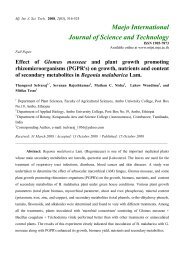
The per phase equivalent circuit <strong>of</strong> SEIG feeding induction motor load at steady state is shown<br />
in Figure 9. In the equivalent circuit, the SEIG parameters R s and X ls are stator resistance and leakage<br />
reactance respectively, R r and X lr are rotor resistance and leakage reactance respectively, and X m is the<br />
magnetising reactance. The corresponding parameters are presented with subscript m for motor load.<br />
X csh is the reactance <strong>of</strong>fered by the capacitor bank, and F and are per unit frequency and prime-mover<br />
speed respectively.<br />
jFX lr<br />
jFX m<br />
jFX ls<br />
R s<br />
-jX csh<br />
/F<br />
R sm<br />
jFX lsm<br />
jFX mm<br />
jFX lrm<br />
R rm<br />
/(F- m<br />
)<br />
R r<br />
/(F-)<br />
I s<br />
Figure 9. Per phase equivalent <strong>of</strong> SEIG feeding motor load<br />
Applying KVL on stator side loop <strong>of</strong> induction generator results in<br />
Z loop I s = 0<br />
Under steady state condition, I s cannot be zero and therefore Z loop<br />
should be zero. An<br />
optimisation problem has been formulated to obtain the unknown variables X csh and F. The objective<br />
function F n is expressed as<br />
Fn( X<br />
csh, F) abs( Zloop)<br />
The values <strong>of</strong> X csh and F should lie between the respective minimum and maximum limits:<br />
Fmn F Fmx , Xcmn Xcsh Xcmx<br />
<br />
The above optimisation problem is solved through SUMT in conjunction with the Rosenbroack<br />
method <strong>of</strong> direct search technique [23]. After the convergence, the capacitance is computed.<br />
Appendix II<br />
The induction machine model is developed in a stationary reference frame while incorporating<br />
the effects <strong>of</strong> both the main flux and cross-flux saturation. The forms <strong>of</strong> v, i, r,<br />
L<br />
and G are<br />
given as<br />
T<br />
T<br />
v v v v v i i i i i r diag r r r r<br />
qs ds qr dr ; qs ds qr dr ; <br />
L<br />
L L L L<br />
<br />
L L L L<br />
<br />
L L L L<br />
<br />
L L L L<br />
sq dq mq dq<br />
dq sq dq md<br />
mq dq rq dq<br />
dq md dq rd<br />
<br />
<br />
<br />
<br />
<br />
<br />
0 0 0 0 <br />
<br />
0 0 0 0<br />
<br />
G <br />
<br />
0 <br />
rLm 0 Lr<br />
<br />
<br />
<br />
rLm 0 Lr<br />
0 <br />
<br />
s s r r<br />
The air gap voltage <strong>of</strong> SEIG does not remain constant during loading. Therefore, the<br />
magnetising inductance is calculated by calculating the magnetising current as<br />
<br />
2 2<br />
m<br />
<br />
qs<br />
<br />
qr<br />
<br />
ds<br />
<br />
dr<br />
i i i i i<br />
The inductances in [L] are evaluated [21] as