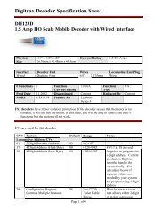
Digitrax Command Control Starter Set Manual - Digitrax, Inc.
Digitrax Command Control Starter Set Manual - Digitrax, Inc.
Digitrax Command Control Starter Set Manual - Digitrax, Inc.

Create successful ePaper yourself
Turn your PDF publications into a flip-book with our unique Google optimized e-Paper software.
R<br />
Complete<br />
T rain<br />
<strong>Control</strong><br />
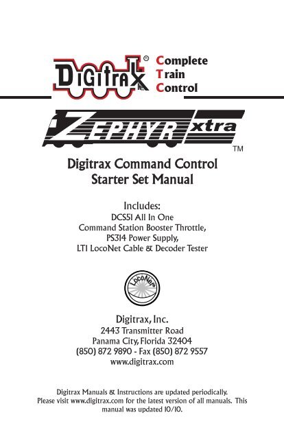
<strong>Digitrax</strong> <strong>Command</strong> <strong>Control</strong><br />
<strong>Starter</strong> <strong>Set</strong> <strong>Manual</strong><br />
TM<br />
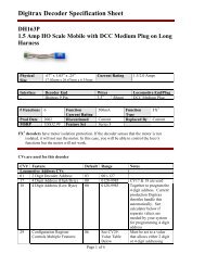
<strong>Inc</strong>ludes:<br />
DCS51 All In One<br />
<strong>Command</strong> Station Booster Throttle,<br />
PS314 Power Supply,<br />
LT1 LocoNet Cable & Decoder Tester<br />
LocoNet<br />
<strong>Digitrax</strong>, <strong>Inc</strong>.<br />
2443 Transmitter Road<br />
Panama City, Florida 32404<br />
(850) 872 9890 - Fax (850) 872 9557<br />
www.digitrax.com<br />
<strong>Digitrax</strong> <strong>Manual</strong>s & Instructions are updated periodically.<br />
Please visit www.digitrax.com for the latest version of all manuals. This<br />
manual was updated 10/10.
<strong>Digitrax</strong>Zephyrxtra<strong>Set</strong><strong>Manual</strong><br />
tableofContents<br />
1.0 Introduction ..................................................................................................4<br />
1.1 Zephyr Xtra Components ............................................................................4<br />
2.0 Quick Start Guide ........................................................................................4<br />
2.1 Unpacking Your Zephyr Xtra ....................................................................4<br />
2.2 Before You Begin ........................................................................................5<br />
2.3 Connecting the Pieces..................................................................................5<br />
2.4 Turn on Track Power ..................................................................................6<br />
2.5 Select & Run Non-DCC Locomotives ........................................................7<br />
2.6 Select & Run DCC Equipped Locomotives ................................................8<br />
3.0 Preparing Your Locomotives ......................................................................9<br />
4.0 Preparing Your Layout................................................................................9<br />
5.0 DCS51 Front Panel <strong>Control</strong>s And Indicators............................................9<br />
6.0 DCS51 Display ............................................................................................11<br />
7.0 Hooking Up Your Zephyr Xtra ................................................................12<br />
7.1 Zephyr Xtra Rear Panel Connections ........................................................12<br />
7.2 Connecting the Zephyr Xtra ....................................................................13<br />
8.0 Run a Locomotive Without a DCC Decoder ..........................................14<br />
9.0 Run a DCC Equipped Locomotive ..........................................................15<br />
9.1 DCC Decoder or Address Basics ..............................................................15<br />
9.2 Selecting and Running your DCC Locomotive ........................................16<br />
9.3 Using the RECALL Key............................................................................17<br />
10.0 Locomotive Direction <strong>Control</strong> ..............................................................18<br />
11.0 Shutting Down the System ......................................................................18<br />
12.0 Resuming Operation ................................................................................18<br />
13.0 Troubleshooting Basic Operation ..........................................................19<br />
14.0 Locomotive Speed <strong>Control</strong> ......................................................................20<br />
14.1 Speed Limit ............................................................................................20<br />
15.0 Stop and Emergency Stop........................................................................20<br />
15.1 <strong>Set</strong>ting a Loco to Zero Speed ..................................................................20<br />
15.2 Brake Operation ......................................................................................20<br />
15.3 Emergency Stop ......................................................................................21<br />
16.0 Programming & Reading Your Decoder ..............................................22<br />
16.1 <strong>Set</strong>ting Up a Programming Track ............................................................22<br />
16.2 Changing & Reading the Decoder Address ............................................24<br />
16.3 Programming Configuration Variables Other Than Addresses ..............25<br />
16.4 Programming On The Mainline: Operations Mode Programming..........27<br />
16.5 Programming Error Messages..................................................................28<br />
16.6 Reading Back CV Values........................................................................28<br />
©2011 <strong>Digitrax</strong>, <strong>Inc</strong>. www.digitrax.com 1
16.7 Configuration Variable (CV) Programming Notes: ................................29<br />
17.0 Functions ..................................................................................................30<br />
17.1 <strong>Control</strong>ling Functions F0-F9 ..................................................................30<br />
17.1.1 Function 0 (F0) Headlights Forward and Reverse ............................30<br />
17.1.2 Functions 1, 4, 5, 6, 7, 8 & 9................................................................30<br />
17.1.3 Function 2 (F2) Momentary Operation ................................................30<br />
17.1.4 Function 3 (F3) Standard or Momentary Operation ............................31<br />
17.1.5 MUTE Function Key (F8) ....................................................................31<br />
17.1.6 Functions 10 through 19 (F10 - F19) ..................................................32<br />
17.1.7 Functions 20 through 28 (F20 - F28) ..................................................32<br />
17.2 Troubleshooting Function Operation ......................................................32<br />
18.0 MU (Multiple Unit) Operations..............................................................32<br />
18.1 Adding a Locomotive to an MU..............................................................33<br />
18.2 Removing a Loco from an MU................................................................35<br />
18.3 MU of Mismatched Locomotives............................................................35<br />
18.4 <strong>Control</strong>ling Functions On MUed Locomotives ......................................35<br />
19.0 Stealing: When an Address Is Running on Another Throttle..............36<br />
20.0 Releasing an Address From a Throttle ..................................................37<br />
20.1 Dispatching Addresses or MUs................................................................37<br />
21.0 The FuLL Message ..................................................................................38<br />
22.0 DCS51 Error Messages............................................................................39<br />
23.0 Decoder Speed Step <strong>Set</strong>tings ..................................................................40<br />
23.1 Changing Speed Step <strong>Set</strong>tings: Status Editing ........................................40<br />
24.0 SWITCH Mode ......................................................................................41<br />
24.1 Saving the last Switch states or settings for your current DCS51 session.<br />
42<br />
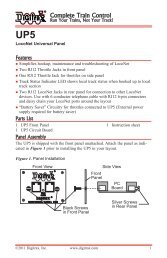
25.0 Adding Throttles: LocoNet & Jump Ports ............................................43<br />
25.1 Adding LocoNet Throttles To Your DCS51 ............................................43<br />
25.2 JUMP Ports: Using a Smooth DC Power Pack As an Additional Throttle<br />
43<br />
25.3 Adding Another DCS51 to your layout ..................................................47<br />
25.3.1 Assigning Throttle Identities ................................................................48<br />
25.3.2 Making LocoNet Cables ......................................................................50<br />
25.3.3 Testing LocoNet Cables with an LT1 ..................................................50<br />
26.0 Clearing the System ................................................................................51<br />
27.0 Troubleshooting General ........................................................................52<br />
27.1 Nothing is responding..............................................................................52<br />
27.2 No Power or Intermittent Operation........................................................52<br />
27.2.1 The Quarter Trick..................................................................................52<br />
27.2.2 The LT1 Tester ......................................................................................52<br />
27.3 Emergency Stop ......................................................................................52<br />
27.4 Mechanical Drive Train Problems ..........................................................52<br />
27.5 “Strange” Locomotive Lights ..................................................................52<br />
27.6 Decoder Won’t Respond ..........................................................................53
27.7 I’m totally lost! ........................................................................................54<br />
27.8 DCS51 Shutdown ....................................................................................54<br />
28.0 DCS51 Option Switch <strong>Set</strong>up ..................................................................54<br />
29.0 LocoNet: The <strong>Digitrax</strong> Difference ..........................................................56<br />
29.1 System Architecture ................................................................................56<br />
29.2 System Expansion ..................................................................................56<br />
30.0 FCC Information......................................................................................57<br />
31.0 <strong>Digitrax</strong> ‘No Worries’ Warranty & Repair ..........................................58<br />
Specifications ....................................................................................................59<br />
Notes...................................................................................................................60<br />
Index...................................................................................................................62<br />
<strong>Digitrax</strong>, the <strong>Digitrax</strong> Train Logos, LocoNet, Super Empire Builder Xtra, Super Chief Xtra, Transponding,<br />
SuperSonic, AutoReversing, Zephyr Xtra, Jump & others are trademarks of <strong>Digitrax</strong>, <strong>Inc</strong>. This manual may not<br />
be reproduced in any form without permission.<br />
©2011 <strong>Digitrax</strong>, <strong>Inc</strong>. www.digitrax.com 3
1.0 Introduction<br />
Congratulations on your purchase of a <strong>Digitrax</strong> Zephyr Xtra <strong>Starter</strong> <strong>Set</strong>!<br />
Your success with and enjoyment of our products are very important to us.<br />
After all, this is a hobby and it is FUN!!! Refer to the Quick Start Guide that<br />
came with your system or follow the steps in the sections below to get up and<br />
running right away. Please read this manual to learn more. We have included<br />
lots of hints and operating ideas based on our experience. The Zephyr Xtra is<br />
designed for easy operation and expandability with <strong>Digitrax</strong> LocoNet. With<br />
LocoNet, just plug in system components to build the layout control system<br />
that you’ve always wanted! If you have questions not covered by this manual<br />
please contact your dealer or <strong>Digitrax</strong> technical support.<br />
1.1ZephyrxtraComponents<br />
Your Zephyr Xtra <strong>Starter</strong> <strong>Set</strong> contains:<br />
DCS51 All-in-one command station, throttle and booster to run your layout<br />
PS314 Power supply to provide power to run your DCS51<br />
LT1 Decoder and LocoNet Cable Tester<br />
Quick Start Guide - To get you up and running<br />
Zephyr Xtra <strong>Manual</strong> - System Reference <strong>Manual</strong><br />
<strong>Digitrax</strong> Decoder <strong>Manual</strong> - Reference for <strong>Digitrax</strong> Decoders<br />
2.0 Quick Start Guide<br />
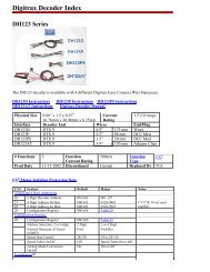
2.1unpackingyourZephyrxtra<br />
Unpack your box and locate the DCS51 <strong>Command</strong> Station and the PS314<br />
power supply.<br />
powerCord<br />
pS314<br />
DCS51<br />
<strong>Command</strong>Station<br />
lt1Decoderandloconet®<br />
Cabletester<br />
DC plug<br />
©2011 <strong>Digitrax</strong>, <strong>Inc</strong>. www.digitrax.com 4
R<br />
2.2BeforeyouBegin<br />
Before proceeding to the next step, make sure the Throttle Knob is turned all<br />
the way to “STOP” and the Direction/Brake lever is set to “BRAKE”<br />
pOWer key<br />
traCK StatuS light<br />
R<br />
SWITC H<br />
SWITC H<br />
4<br />
4<br />
2.3Connectingthepieces<br />
On the back of the DCS51, locate the gray screw terminal strip.<br />
On this strip, locate the two terminals labeled “RAIL A” and “RAIL B”.<br />
Attach your layout track wires to these terminals.<br />
It does not matter which is which. Find the jack on the back of the DCS51<br />
marked “POWER IN, 13.8 V DC, 3.5 AMPS” Plug the PS314 DC plug into<br />
this jack and then connect the PS314 into an AC outlet that matches the power<br />
cord on the PS314. The PS314 will work universally on 110 through 240V AC<br />
Screwterminalstrip<br />
PS314<br />
or similar DC<br />
supply<br />
©2011 <strong>Digitrax</strong>, <strong>Inc</strong>. www.digitrax.com 5
2.4turnontrackpower<br />
1. On the front panel of the DCS51, locate the key marked “POWER” It is on<br />
the left hand column of keys.<br />
2. When you push it, the orange “TRACK STATUS” light will come on.<br />
pOWer key<br />
traCK StatuS light<br />
R<br />
SWITC H<br />
4<br />
©2011 <strong>Digitrax</strong>, <strong>Inc</strong>. www.digitrax.com 6
2.5Select&runnon-DCClocomotives<br />
1. To select a non-DCC equipped (Analog) locomotive to run, look at the main<br />
group of keys on the front panel. Locate the one labeled “LOCO”.<br />
2. Press this key ONCE, enter “00” and press “LOCO” once again. You have<br />
selected a locomotive to run!<br />
3. To run the locomotive, place the locomotive on your layout, move the<br />
Direction/Brake lever to either ‘FORWARD” or “REVERSE”, depending<br />
on which way you want the locomotive to move, and slowly turn the<br />
Throttle clockwise until the locomotive starts to move.<br />
4. If your locomotive runs in the opposite direction of the throttle setting, turn<br />
the locomotive around.<br />
5. To stop the locomotive, either turn the Throttle back to “STOP,” or shift the<br />
Direction/Brake lever to “BRAKE”.<br />
lOCO key<br />
Keypad<br />
R<br />
E X IT<br />
SWITC H<br />
P O W ER<br />
4<br />
PRO G<br />
MOD E<br />
Direction/Brakelever in “FOrWarD”position<br />
©2011 <strong>Digitrax</strong>, <strong>Inc</strong>. www.digitrax.com 7
2.6Select&runDCCequippedlocomotives<br />
Most new decoders and DCC-equipped locomotives have their decoder address<br />
factory set to “03.” Other DCC-equipped locomotives may have had their<br />
address changed. To run a DCC-equipped loco, you must know its address.<br />
For detailed instructions on reading the address, see the section 16.2 Steps 1-4.<br />
For now, let’s assume you are using a brand-new, DCC-equipped loco that is<br />
set to address “03.” To select this locomotive, press the key labeled “LOCO”<br />
ONCE, enter “03” on the keypad, and press “LOCO” once again. You have<br />
selected a DCC loco!<br />
To run the locomotive, move the Direction/Brake lever to either<br />
‘FORWARD” or “REVERSE”, depending on which way you want the loco to<br />
move, and slowly turn the Throttle clockwise until the locomotive starts to<br />
move. To stop the loco, either turn the Throttle back to “STOP,” or shift the<br />
Direction/Brake lever to “BRAKE.”<br />
lOCO key<br />
Keypad<br />
R<br />
SWITC H<br />
4<br />
STOP HERE!<br />
This is the end of the Quick Start Section of the<br />
manual. You should now be able to run both a DCC<br />
locomotive and a non-DCC locomotive at this point.<br />
Enjoy running trains for a few minutes before you dive<br />
in to the rest of the manual. The remaining sections of<br />
the manual go into more detail about the capabilities of<br />
the Zephyr Xtra. When you are ready to learn more, read on!<br />
©2011 <strong>Digitrax</strong>, <strong>Inc</strong>. www.digitrax.com 8
If you have trouble with any of the steps above, please refer to Section 13.0<br />
Troubleshooting Basic Operation.<br />
3.0 Preparing Your Locomotives<br />
You will be able to run one locomotive without a decoder on your Zephyr Xtra<br />
system along with the ones with decoders. So, even if you don’t have a loco<br />
with a decoder, you can still hook up your new system and try it out right<br />
away!<br />
You will need to install decoders in the locomotives you want to run in order to<br />
take full advantage of your new <strong>Digitrax</strong> <strong>Command</strong> <strong>Control</strong> system. The<br />
decoder allows you to individually control each locomotive’s speed, direction,<br />
lights and other functions. We don’t include decoders with our starter sets<br />
because there are so many different decoders available for so many different<br />
locomotives. We want to be sure you don’t spend money on a decoder that may<br />
not be the best choice for your particular locomotives. Your dealer can help you<br />
select the best decoder choices for your layout from <strong>Digitrax</strong> wide variety of<br />
decoders. Our web site www.digitrax.com contains information about decoder<br />
installations and which decoders are best for particular locomotives.<br />
A <strong>Digitrax</strong> Decoder <strong>Manual</strong> is included with all <strong>Starter</strong> <strong>Set</strong>s so you will have it<br />
available to use with any <strong>Digitrax</strong> decoders you purchase.<br />
4.0 Preparing Your Layout<br />
<strong>Digitrax</strong> simplifies layout wiring for new layouts. If you already have a layout,<br />
you probably won’t need to rewire to install your <strong>Digitrax</strong> Zephyr Xtra. Since<br />
the DCC signal travels with the power on the rails, you must have power to the<br />
track in all locations so that the decoders can receive the signal and respond to<br />
your commands.For more information about layout wiring visit our web site.<br />
5.0 DCS51 Front Panel <strong>Control</strong>s And Indicators<br />
Before you select and run a locomotive, take a few minutes to look at the<br />
DCS51’s controls and display.<br />
1. The Throttle Knob is the large silver and black knob on the right side of<br />
the DCS51. The Throttle Knob controls locomotive speed from StOp to<br />
Full speed. Turn it clockwise to increase speed and counter clockwise to<br />
decrease speed.<br />
2. The Direction <strong>Control</strong> Lever is the small silver lever (located on the left<br />
side of the DCS51) that controls the locomotive’s direction of travel,<br />
FOrWarD or reverSe. This knob also controls the BraKe.<br />
3. When you have a loco address selected and the Direction <strong>Control</strong> Lever<br />
lever is in the BraKe position, the Brake Indicator Light will blink until<br />
the loco stops and then remain on steady to let you know that the BraKe is<br />
on. When you move the lever to FOrWarD or reverSe, the Brake<br />
Indicator Light will flash to let you know that the brake is released and the<br />
loco is accelerating to the speed shown on the Throttle Knob.<br />
4. There are 24 KeyS on the DCS51’s keypad, including a full numeric keypad<br />
for direct entry of numeric values. Some keys have more than one use<br />
©2011 <strong>Digitrax</strong>, <strong>Inc</strong>. www.digitrax.com 9
when used in combination with other keys or sequences of keystrokes.<br />
5. The TRACK STATUS Light is lit when track power is on and unlit when<br />
track power is off. Track power must be on to operate the trains on the<br />
track. Simply press the pOWer key to toggle between power on and off. If<br />
you need to stop the whole layout, press the pOWer key to turn off track<br />
power and put everything on the layout into “Emergency Stop.”<br />
5 4<br />
R<br />
E X IT<br />
SWITC H<br />
P O W ER<br />
4<br />
PRO G<br />
MOD E<br />
2<br />
3<br />
1<br />
©2011 <strong>Digitrax</strong>, <strong>Inc</strong>. www.digitrax.com 10
6.0 DCS51 Display<br />
The DCS51’s Display is made up of 4 digits/letters on the main part of the<br />
screen and 4 Indicator Dots across the top of the screen.<br />
When you are running a locomotive, you will see the address of that locomotive<br />
in the display and the Function Indicator Dot will be lit. This means that<br />
the throttle knob will control speed, the direction lever will control direction<br />
and braking and the number keys will control the functions on the locomotive.<br />
You will see the following display if you are running loco address 1873 on<br />
your local throttle.<br />
The Display has three additional Indicator Dots associated with more advanced<br />
features available on the DCS51:<br />
The JUMP Indicator Dot lets you know if one or more Jump ports are active.<br />
See Section 25.2.<br />
The MU Indicator Dot lets you know if Multiple Unit (MU) or consisting is<br />
active. See Section 18.<br />
The SWITCH Indicator Dot lets you know when you are in switch mode for<br />
controlling turnouts or setting up system options. See Section 24 for turnout<br />
operation and Section 28 for Option Switch set up information.<br />
©2011 <strong>Digitrax</strong>, <strong>Inc</strong>. www.digitrax.com 11
7.0 Hooking Up Your Zephyr Xtra<br />
7.1ZephyrxtrarearpanelConnections<br />
1. raila & B for connecting the DCS51 to the rails on the layout.<br />
2. prOga & B for hooking up the programming track. Section 16.1.<br />
3. JuMp 1 & 2 for connecting one or two smooth DC power packs to the system<br />
for use as additional throttles. Section 25.2<br />
4. pOWerin-plug in the PS314 here.<br />
5. lOCOnetpOrtSa & B for connecting the DCS51 to other LocoNet<br />
devices for expanding your layout.<br />
6. yOurlayOut. You can connect Zephyr Xtra to most existing layouts.<br />
3 2 1 5<br />
6<br />
4<br />
pS314<br />
orsimilar<br />
DCsupply<br />
©2011 <strong>Digitrax</strong>, <strong>Inc</strong>. www.digitrax.com 12
7.2ConnectingtheZephyrxtra<br />
These simple instructions will help you get up and running quickly. A full<br />
description of all controls and technical reference information are included later<br />
in this manual. This section assumes that you are using a new set straight out of<br />
the box.<br />
1. Hook up the wires from the track to the raila & railB terminals on<br />
the DCS51. Insert the wire from one rail of the track into the raila terminal<br />
on the back of the DCS51. Insert the wire from the other rail of the<br />
track into the railB terminal. Turn the screw counter clockwise to open<br />
the connector and clockwise to close it once the wire is in place.<br />
2. Plug the barrel connector from the PS314 into the pOWerin jack on the<br />
back of the DCS51. Plug the body of the PS314 in to a regular wall outlet.<br />
Once power is applied, the DCS51 will<br />
briefly flash “-cS-” to let you know it is<br />
running as a command station.<br />
The DCS51’s display will change automatically<br />
to “Loco” or the last address that<br />
was on the throttle when you turned it off.<br />
3. Turn track power on. Check the TRACK STATUS Light. If it is on, you<br />
are ready to go. If the TRACK STATUS Light is unlit, press the pOWer<br />
key (located on the left side of the keypad) to turn track power on. When<br />
track power is on the TRACK STATUS Light will be lit.<br />
The following examples will help you learn about your new DCS51. The<br />
first example shows how to select and run a locomotive without a DCC<br />
decoder. The second example shows how to select and run a DCC decoder<br />
equipped locomotive.<br />
©2011 <strong>Digitrax</strong>, <strong>Inc</strong>. www.digitrax.com 13
8.0 Run a Locomotive Without a DCC Decoder<br />
In the proceeding steps you familiarized yourself with the controls and connected<br />
the Zephyr Xtra to your layout. Just follow these simple steps and you’ll<br />
be running one of your existing DC locomotives in just a few more minutes.<br />
1. <strong>Set</strong> the DCS51’s Throttle Knob to StOp.<br />
2. Place an analog locomotive, one without a decoder installed, on your layout<br />
that is controlled by your DCS51.<br />
3. Check the DCS51’s TRACK STATUS Light to be sure that track power is<br />
turned on. Press pOWer to turn track power on if necessary.<br />
4. Press the lOCO key to begin the selection process. The Display will begin<br />
flashing either “lOCO” or the last address selected on the throttle.<br />
5. Use the numeric keypad to enter “00”, the address used to control the locomotive<br />
without a decoder. Your display will show:<br />
6. Press the lOCO key again to confirm your selection and set address 00 on<br />
the throttle. The display will stop blinking and you will have control of the<br />
analog locomotive.<br />
7. <strong>Set</strong> the Direction <strong>Control</strong> Lever to FOrWarD and turn the Throttle<br />
Knob clockwise slowly to increase the speed of the analog locomotive. As<br />
the speed increases, the locomotive on the track will begin to move. The<br />
direction of an analog locomotive is determined by track polarity not by the<br />
DCC signal so, you may have to turn your analog locomotive around to<br />
match the direction of travel on the Direction <strong>Control</strong> Lever. The DCS51’s<br />
©2011 <strong>Digitrax</strong>, <strong>Inc</strong>. www.digitrax.com 14
TRACK STATUS Light should slightly change color as you change the<br />
speed setting.<br />
8. Change the Direction <strong>Control</strong> Lever to reverSe and the loco will move<br />
in the opposite direction.<br />
9. Change the Direction <strong>Control</strong> Lever to the BraKe position and the loco<br />
will slow down and stop. Move the Direction <strong>Control</strong> Lever to FOrWarD<br />
or reverSe and the loco will move again.<br />
10.Turn the Throttle Knob to StOp and the loco will stop moving.<br />
11. If you have a headlight installed in your loco, it will be on and stay on<br />
because with DCC there is constant power to the track.<br />
A locomotive without a DCC decoder is called an analog locomotive. While<br />
an analog locomotive, without a decoder, is sitting still on your digital layout,<br />
you will hear a “singing” sound. This is caused by the DCC track signal when<br />
it is applied to an analog locomotive. Once the analog locomotive is moving,<br />
this sound will change and be less noticeable. To avoid heat build up in your<br />
locos without decoders, <strong>Digitrax</strong> recommends that analog locos NOT be left<br />
sitting on DCC powered track for long periods of time when they are not running.<br />
Address 00 is reserved for running an analog locomotive. Your analog locomotives<br />
will not run with any other address. As with a regular DC system, only<br />
one analog locomotive can be controlled at a time. If you try to run more than<br />
one analog locomotive at the same time on the layout all of the analog locos<br />
will respond to the commands sent to address 00. By adding DCC decoders to<br />
your locomotives and additional throttles to your system, you can individually<br />
control up to 20 locomotives at the same time with your Zephyr Xtra <strong>Set</strong>.<br />
9.0 Run a DCC Equipped Locomotive<br />
9.1DCC DecoderoraddressBasics<br />
1. Each DCC decoder can be assigned a unique DCC decoder address that is<br />
used by the system to send commands to that decoder. The address is a<br />
numeric value remembered by the decoder in the loco until you change it.<br />
2. You program each of your locomotives with its own unique address so that<br />
you can run them independently.<br />
3. To select a DCC locomotive and run it, you must know its address.<br />
4. <strong>Digitrax</strong> decoders are set up at the factory with address 03. This means that<br />
when you take a <strong>Digitrax</strong> decoder out of the package and install it in your<br />
loco, you can select address 03 on your throttle and run the decoder. You<br />
can easily change this address by following the instructions in Section 16.2.<br />
To make the examples easier to follow, let’s leave everything at the factory<br />
settings for now.<br />
©2011 <strong>Digitrax</strong>, <strong>Inc</strong>. www.digitrax.com 15
5. If you do not know the address of the DCC locomotive you want to run,<br />
you can either read back the decoder’s address or program it to the address<br />
you want to use. Section 16.6 shows how to read back the decoder address.<br />
9.2SelectingandrunningyourDCClocomotive<br />
To select and run a DCC equipped locomotive with a known address follow<br />
these steps:<br />
1. <strong>Set</strong> the DCS51’s Throttle Knob to StOp.<br />
2. Place a DCC equipped locomotive (one with a decoder installed) on your<br />
digital layout that is controlled by your DCS51. In this example we assume<br />
that you have a new <strong>Digitrax</strong> decoder that is factory programmed to address<br />
03. If your decoder is using a different address, simply use that address as<br />
you follow these instructions.<br />
3. Check the DCS51’s TRACK STATUS Light to be sure that track power is<br />
turned on. Press the pOWer key to turn track power on if necessary.<br />
4. Press the lOCO key to begin the selection process. The Display will begin<br />
flashing either “Loco” or the last address selected on the throttle. If you are<br />
continuing on from the previous example of running an analog locomotive,<br />
your display will be blinking address 00 as shown here since 00 was the last<br />
address you used:<br />
5. Use the numeric keypad to enter “03”, the address used to control the locomotive<br />
with the decoder. Your display will show:<br />
6. Press the lOCO key again to confirm your selection and set address 03 on<br />
the throttle. The display will stop blinking and you will have control of the<br />
DCC equipped locomotive with address 03.<br />
©2011 <strong>Digitrax</strong>, <strong>Inc</strong>. www.digitrax.com 16
7. <strong>Set</strong> the Direction <strong>Control</strong> Lever to FOrWarD and turn the Throttle<br />
Knob clockwise slowly to increase the speed of the locomotive. As the<br />
speed increases, the locomotive on the track will begin to move forward.<br />
The direction of digital locomotives is determined by the DCC signal so,<br />
forward means that the loco will move in the direction the decoder is set up<br />
to recognize as forward.<br />
8. Change the Direction <strong>Control</strong> Lever to reverSe and the loco will move<br />
in the reverse direction.<br />
9. Change the Direction <strong>Control</strong> Lever to the BraKe position and the loco<br />
will slow down and stop. Move the Direction <strong>Control</strong> Lever back to<br />
FOrWarD or reverSe and the loco will move again.<br />
10.Turn the Throttle Knob to StOp and the loco will stop moving.<br />
11. If you have a headlight installed in your loco, press the laMp/0 key to<br />
toggle between lights on and off. Many DCC-ready locomotives have directional<br />
lighting installed, with headlight/back-up light operating depending<br />
on direction of travel of the locomotive. If you have other functions<br />
installed in your loco, you can operate them by pressing the associated<br />
number key for the function you want to operate. You must have sound<br />
capability installed in your locomotive in order to operate the sound functions<br />
(Bell/1 and WhiStle/2 keys and others).<br />
9.3usingthereCallKey<br />
The Zephyr Xtra’s RECALL feature allows you to change control among<br />
recently used addresses without the need to re-enter the address each time.<br />
The factory default is a 2 address recall stack which allows you to switch<br />
quickly between the last two loco addresses that you used. You can increase<br />
this to 4 or 8 entries, see below for instructions.<br />
1. To switch control from the loco address currently in use to the last address<br />
used, press the RECALL key. The display will bring up the previously used<br />
address.<br />
2. Press the RECALL key to cycle through the addresses available for recall.<br />
Each address will appear in the display and be flashing indicating that it is<br />
available for selection.<br />
3. When the loco address you want to control appears in the display, press the<br />
LOCO key to begin controlling that address.<br />
To change to a 4 address stack, change OpSw10 to closed and OpSw11 to<br />
thrown<br />
©2011 <strong>Digitrax</strong>, <strong>Inc</strong>. www.digitrax.com 17
To change to an 8 address stack, change OPSW11 to closed.<br />
To change to a 2 address recall stack set both OpSw10 & OpSw11 to thrown<br />
(this is the factory default setting). See section 28.0 for option switch set up<br />
instructions.<br />
10.0 Locomotive Direction <strong>Control</strong><br />
Move the Direction <strong>Control</strong> Lever to FOrWarD or reverSe to change the<br />
direction of the loco address running on the throttle. To determine the direction<br />
of a loco that is not moving, simply look at the position of the lever. You can<br />
move the lever quickly past the BraKe position with no adverse effects.<br />
If you change direction while a loco is moving it will slow down to 0 speed<br />
and then speed up to the commanded speed according to the decoder’s programmed<br />
CV values for deceleration and acceleration.<br />
11.0 Shutting Down the System<br />
When you are finished with your session, you should shut down the DCS51 by<br />
turning off power to the system.<br />
1. Bring all locomotives on the layout to a stop by setting set the Throttle<br />
Knob for each loco to StOp.<br />
2. Turn track power off: Press the pOWer key, the DCS51’s TRACK STA-<br />
TUS Light will go off. The display will briefly display “Po” followed by<br />
two characters, the Po means power off, the two characters indicate which<br />
software version is installed in the unit. The display will automatically<br />
revert to showing the last loco address selected on the throttle but since<br />
track power is now off, it will not run the layout until you turn on track<br />
power again.<br />
3. Unplug the PS314 power supply from the wall outlet.<br />
When power is restored to the DCS51, it will “wake up” with all of the settings<br />
as they were left when powered down. The power to the command station can<br />
be left on all the time if desired.<br />
12.0 Resuming Operation<br />
When you are ready to run trains again:<br />
1. <strong>Set</strong> the DCS51’s Throttle Knob to StOp.<br />
2. Plug in the PS314 power supply to the wall outlet and to the DCS51.<br />
3. Press the pOWer key to turn on track power. The TRACK STATUS Light<br />
will light up.<br />
4. The DCS51 display will show the last locomotive address you were running<br />
and be ready to begin right where you left off.<br />
©2011 <strong>Digitrax</strong>, <strong>Inc</strong>. www.digitrax.com 18
If you have trouble with any of the steps above, please refer to Section 13.0<br />
Troubleshooting Basic Operation.<br />
13.0 Troubleshooting Basic Operation<br />
If you encountered problems at any step in this Quick Start Section:<br />
1. Try backing up a step until you get results described. The steps included in<br />
this installation procedure are set up so that if you follow them carefully,<br />
any problems you encounter will be easy to isolate and correct.<br />
2. If you still have problems or if you have other questions, we encourage you<br />
to call, fax or e-mail your favorite <strong>Digitrax</strong> dealer. If your dealer is not able<br />
to help, please contact <strong>Digitrax</strong> techsupport directly.<br />
There are thousands of successful <strong>Digitrax</strong> installations around the world and<br />
we want to be sure that yours is one of them.<br />
Notes for users of decoders without 128 speed step capability:<br />
Some non-<strong>Digitrax</strong> decoders are not able to run in 128 speed step mode.<br />
<strong>Digitrax</strong> decoders are capable of 128 speed step control but can be programmed<br />
otherwise.<br />
1. The DCS51 command station operates in 128 speed step mode. If you are<br />
using a locomotive with a decoder that does not have 128 step capability<br />
you will have to adjust either the decoder or the DCS51 so that both are<br />
using the same number of speed steps to communicate. We call this procedure<br />
status editing. You can status edit each individual decoder (see<br />
Section 23) or you can change the DCS51’s system default by setting the<br />
DCS51’s Option Switches 21-23 and run all of your decoders with fewer<br />
speed steps to accommodate these decoders (see Section 28).<br />
2. If you can’t control the operation of the lights in your decoder equipped<br />
locomotive with the DCS51, be sure that the decoder itself is programmed<br />
to run in 128 speed steps.<br />
What’s Next<br />
Now that you have successfully set up and run your Zephyr Xtra <strong>Set</strong>, it’s time<br />
to learn more about the features and options it has to offer.<br />
Please read the manual and take time to understand and master each topic. Your<br />
Zephyr Xtra <strong>Set</strong> is the gateway to all the possibilities and options offered by<br />
<strong>Digitrax</strong> and LocoNet so the best advice is to take it step by step and don’t try<br />
to do everything at once.<br />
©2011 <strong>Digitrax</strong>, <strong>Inc</strong>. www.digitrax.com 19
14.0 Locomotive Speed <strong>Control</strong><br />
To control the speed of a locomotive:<br />
1. Select the loco address on the throttle.<br />
2. Turn the Throttle Knob clockwise to increase speed and counterclockwise<br />
to decrease speed.<br />
14.1Speedlimit<br />
You can limit top speed on any locomotive controlled by the DCS51. This feature<br />
is very useful if you are running your layout with young children who<br />
want to make the trains GO FAST!!! By setting a reasonable speed limit on the<br />
throttles used by the children, everyone can have more fun with the trains.<br />
To set a “speed limit” for your DCS51’s local throttle follow these simple<br />
steps:<br />
1. Press the prOg key. The display shows the last programming mode used.<br />
2. Press the Mu key. The display shows “id00”.<br />
3. Press the Mu key again. The display shows SPXX where XX is the current<br />
speed limit set for this DCS51. We recommend a value in the range of 26<br />
(lowest speed limit) to 99 (full speed limit). DCS51 is shipped from the factory<br />
set for SP99.<br />
4. Use the keypad to enter the new speed limit for the throttle.<br />
5. Press the exit Key to set the selected speed limit and resume operation.<br />
Once you set this speed limit, it will be in effect for this specific DCS51’s<br />
local throttle until you change it. <strong>Set</strong>ting the speed limit will not affect any<br />
Jump Throttles or other throttles that are in use.<br />
15.0 Stop and Emergency Stop<br />
15.1<strong>Set</strong>tingalocotoZeroSpeed<br />
To immediately stop a locomotive:<br />
Make sure the loco address is selected on the throttle and turn the Throttle<br />
Knob counterclockwise until it is in the StOp position. The loco should slow<br />
to a stop as you rotate the throttle knob. This lets you slow down your loco and<br />
stop it prototypically. If you have set up deceleration (CV4) for the loco and<br />
you move the throttle knob to StOp, your loco will slow down and come to a<br />
stop at the programmed deceleration rate.<br />
15.2BrakeOperation<br />
To use the pre-set braking rate to stop and start a locomotive:<br />
Move the Direction <strong>Control</strong> Lever to the BraKe position, the Brake<br />
Indicator Light will begin blinking and the loco will slow down to a stop at<br />
the brake rate you have set up in the DCS51. As the loco slows to a stop, the<br />
Brake Indicator Light will change from blinking to steady on to let you know<br />
that the brake is on.<br />
©2011 <strong>Digitrax</strong>, <strong>Inc</strong>. www.digitrax.com 20
Move the Direction <strong>Control</strong> Lever to the FOrWarD or reverSe position<br />
and the loco will accelerate at the programmed brake rate to the speed on the<br />
throttle knob. As the loco accelerates, the BRAKE Indicator Light will flash<br />
during acceleration and go off when the loco has reached the speed set on the<br />
Throttle Knob.<br />
The DCS51 is shipped with the brake rate set at 02. This gives a small amount<br />
of deceleration when the brake is applied and a small amount of acceleration<br />
when the brake is released.<br />
To change the brake rate:<br />
1. Press the prOg key. The display shows the last programming mode used.<br />
2. Press the Mu key. The display shows id00.<br />
3. Press the Mu key again. The display shows SPXX where XX is the current<br />
speed limit set for this DCS51.<br />
4. Press the Mu key again. The display shows brXX where XX is the current<br />
brake rate set for this DCS51.<br />
Use the keypad to enter the<br />
new brake rate for the<br />
DCS51. <strong>Set</strong>ting brake rate at 00 turns the brake feature off. A setting of 01<br />
gives a fast braking (deceleration rate) and startup (acceleration rate) effect<br />
and a setting of 15 gives the slow braking (deceleration rate) and startup<br />
(acceleration rate) effect when the brake is used.<br />
5. Press the exit key to set the new braking rate and return to normal operation.<br />
NOTE: Changing the brake rate only affects the locomotive controlled by<br />
the DCS51 throttle. It does not affect the the decoder programming.<br />
Braking can also be handled on a loco by loco basis if you set up each decoder<br />
with acceleration and deceleration rates that simulate the scale effects of braking<br />
the train. Then when you command an instant reverse, the system will simulate<br />
braking by slowing down the locomotive at the programmed deceleration<br />
rate, come to a stop and then accelerate at the programmed acceleration rate in<br />
the opposite direction.<br />
15.3emergencyStop<br />
To stop everything on the layout immediately:<br />
Press the pOWer key to turn off power to the whole layout. This option will<br />
stop everything on the layout. Do not turn Track Power off during a short.<br />
Clear the short first. The Zephyr Xtra shuts off when it sees a short to protect<br />
itself.<br />
Having Trouble Stopping If the deceleration CV value you set for a particular<br />
loco is very large, this can make it look like the loco is not stopping on<br />
command because the deceleration CV value is causing the loco to take a long<br />
time to come to a stop.<br />
©2011 <strong>Digitrax</strong>, <strong>Inc</strong>. www.digitrax.com 21
16.0 Programming & Reading Your <strong>Digitrax</strong> Decoders<br />
Your DCC Decoders have many different configuration variables (CVs for<br />
short) that let you set up a different set of characteristics for each decoder<br />
installed in a locomotive. When you want to change a loco’s address, set up<br />
how its lights work, change its momentum characteristics, etc. you will program<br />
new CV values into the appropriate CVs to set it up just the way you<br />
want.<br />
Each CV controls a characteristic of the decoder. See your decoder manual for<br />
a list of the most commonly used CVs and their meanings. A <strong>Digitrax</strong> Decoder<br />
<strong>Manual</strong> is included as a part of your Zephyr Xtra system. Each decoder comes<br />
pre-programmed with factory settings that will let you run it right away. We<br />
recommend that you use the factory settings until you are comfortable with<br />
running your layout with Digital <strong>Command</strong> <strong>Control</strong>. If you are using non-<br />
<strong>Digitrax</strong> decoders or sound decoders, please consult the manual provided by<br />
the manufacturer for how CV’s are used and programming instructions.<br />
The factory set address for all <strong>Digitrax</strong> decoders is 03. This is the first CV you<br />
will want to change because it is not very useful to have all of your locos<br />
respond to the same address.<br />
Decoders are programmed when the command station sends programming<br />
information to them through the rails. Your DCS51 supports two types of programming:<br />
Service Mode Programming is done on an electrically isolated programming<br />
track. Using this mode, the command station broadcasts programming information<br />
to all decoders on the program track. Because this is a broadcast mode,<br />
you must isolate the decoder you want to program from the others on the layout<br />
by using a separate programming track that is connected to the command<br />
station for programming but not powered for operation of the locomotive. This<br />
mode works with all DCC decoders. This is the most commonly used programming<br />
method.<br />
Operations Mode Programming is done on the layout by sending programming<br />
commands to a specific locomotive address while they are powered on<br />
the mainline or main layout track. To use this mode, you must have decoders<br />
that are capable of operations mode programming. The programming track is<br />
not used when using ops mode programming.<br />
16.1<strong>Set</strong>tingupaprogrammingtrack<br />
Your DCS51 has two sets of DCC outputs. This means that you will be able to<br />
program decoders using one set of DCC outputs while the layout is running on<br />
the other set of DCC outputs. When you hooked up your DCS51 to the layout,<br />
you used the raila& railB connections to the track. Now we will use the<br />
prOg a& prOgB outputs to set up a programming track.<br />
nOte: The programming track is powered for programming only and cannot<br />
run locomotives. You will have to manually move your locomotive on to the<br />
track whether using the siding or isolated track programming setup.<br />
©2011 <strong>Digitrax</strong>, <strong>Inc</strong>. www.digitrax.com 22
DCS51rearpanelprogrammingtrackhookupDiagram<br />
Rail A<br />
Rail B<br />
pS314<br />
orsimilar<br />
DCsupply<br />
Your programming track can be as simple as a spare piece of track not connected<br />
to the layout as shown above or it can be a double gapped section of track<br />
connected to the DCS51’s prOga&prOgB outputs as shown below.<br />
programmingtrackexampleDiagram<br />
©2011 <strong>Digitrax</strong>, <strong>Inc</strong>. www.digitrax.com 23
16.2Changing& readingtheDecoderaddress<br />
1. Be sure that only the locomotive you want to program is on the programming<br />
track if you use Direct, Paged or Physical CV programming.<br />
2. Press the prOg key on the DCS51 to enter programming mode. The<br />
DCS51 will display one of the programming modes available. <strong>Digitrax</strong> recommends<br />
the Direct Mode when you are using the programming track. If<br />
you press the PROG key repeatedly, you will cycle through the following<br />
programming choices: dir, OPS, PAGE, PHYS. See Table 1 for display<br />
sequence.<br />
Once the mode you want to use is on the screen you can go to step 3.<br />
For example, to use Direct mode stop pressing the prOg key when the following<br />
screen appears:<br />
If you are not using Direct programming, see Table I: DCS51 Programming<br />
Display Table at the end of Section 16.3 for information about how your<br />
display will be different from this example.<br />
3. Press the lOCO key and you will see either Ad2 or Ad4 in the display.<br />
Ad2 = two digit address (address must be between 01-127)<br />
Ad4 = four digit address (address must be between 0128-9983)<br />
Each time you press the lOCO key the display will toggle between Ad2 and<br />
Ad4. When the one you want to use is in the display move to the next step.<br />
4. Press the Cv-rD key to to read back the address programmed into the<br />
decoder. Your display will show Ad2 or Ad4 while it is reading then it will<br />
display the decoder’s currently programmed address.<br />
When reading back addresses, 2 digit addresses are displayed with 3 digits,<br />
(001 through 127) and 4 digit addresses are displayed with 4 digits (0128<br />
through 9983). Address 00 is reserved for analog locomotive operation.<br />
For example, if 03 is the two digit address, the read back display will show:<br />
If 268 is the four digit address, the read back display will show:<br />
5. To change the address of the loco, press the lOCO key to choose Ad2 or<br />
press the lOCO key again for Ad4. Enter the address number you want to<br />
use for the loco, using 1through 127 for a two digit address (AD2) and 128-<br />
9999 for a four digit address(AD4).<br />
HINT: Many operators use the locomotive number or the last two digits of<br />
the number for the decoder/locomotive address.<br />
©2011 <strong>Digitrax</strong>, <strong>Inc</strong>. www.digitrax.com 24
6. Press the Cv-Wr key to write the address to the decoder. The display will<br />
flicker while the address is programmed and then will show the new address<br />
in the display.<br />
For example, to change the address from the two digit address 03 to the two<br />
digit address 96, press the lOCO Key until Ad2 appears in the display then<br />
use the key pad to enter 96 and press the Cv-Wr key to write the address.<br />
7. When you are finished programming the address, press the exit key. You<br />
are now ready to resume normal operations or proceed to programming<br />
other configuration variables.<br />
For convenience the DCS51 will automatically return to the last Programming<br />
mode and CV number when programming is used the next time.<br />
16.3programmingConfigurationvariables Otherthanaddresses<br />
There are many different CVs that have been defined to control the operating<br />
characteristics of your locomotives. Your decoder manual has a complete listing<br />
of CVs that are available in specific decoders, what they do and suggested<br />
values for each CV. Programming these CVs is simple:<br />
1. Be sure that only the locomotive you want to program is on the programming<br />
track (if using Operatiosn mode the loco will need to be on the mainline).<br />
2. Press the prOg Key to enter programming mode. The DCS51 will display<br />
one of the programming modes available. <strong>Digitrax</strong> recommends the Direct<br />
Mode when you are using the programming track. As you press the prOg<br />
Key repeatedly, you will cycle through the following choices:<br />
dir, OPS,PAGE, PHYS,<br />
Once the mode you want to use is on the screen you can go to step 3.<br />
For example, to use Direct mode stop pressing the prOg Key when the following<br />
screen appears:<br />
3. Press the Cv Key and you will see P followed by the last CV number used<br />
by the DCS51. The “t” indicates that you are in Direct programming mode.<br />
4. Enter the CV number you want to program. For example, if you want to set<br />
up acceleration which is controlled by CV03, use the keypad to enter 3.<br />
5. Press the Cv-rD key to to read back the data value currently programmed<br />
into the decoder for the CV selected. Your screen will show something like<br />
this:<br />
©2011 <strong>Digitrax</strong>, <strong>Inc</strong>. www.digitrax.com 25
The numbers will flash for a few seconds as the DCS51 command station<br />
reads back the data value in the decoder. The “d” means that you are looking<br />
at the CV’s data value that is programmed into the decoder, in this case the<br />
CV value is 0.<br />
6. Use the numeric key pad to enter the new CV data value you want to program<br />
into the decoder. For example if you want to program the value of 2<br />
for CV03 which controls acceleration, enter 2.<br />
Note: If you do not want to read back the CV’s data value as described in<br />
step 5, you can simply press the CV Key again to go directly to the data<br />
entry mode. In this case, the display will show “d” followed by 3 digits.<br />
When you see this display, use the key Pad to enter the new data value you<br />
want to program.<br />
7. Press Cv-Wr to write the new data value selected to the CV. The display<br />
will show the data value programmed.<br />
8. To program another CV, press the Cv key and enter the CV number you<br />
want to program next and repeat steps 3-7 again.<br />
9. When you are finished programming, press the exit key to resume normal<br />
operations.<br />
taBlei:DCS51programmingDisplay table<br />
i<br />
a<br />
a<br />
i<br />
a<br />
a<br />
i<br />
a<br />
a<br />
i<br />
a<br />
a<br />
a<br />
a<br />
If you are using a programming mode other than Direct mode see Table<br />
1 for the meanings of the screens you will see.<br />
©2011 <strong>Digitrax</strong>, <strong>Inc</strong>. www.digitrax.com 26
16.4programmingOntheMainline:OperationsMode<br />
programming<br />
Operations (OPS) Mode Programming lets you program CVs in DCC locomotives<br />
equipped with Extended Packet Format decoders while they are on the<br />
mainline. A typical use for OPS mode programming would be to change the<br />
acceleration rate (CV03) or the deceleration rate (CV04) of your locomotives<br />
to simulate the weight and braking capability of the train to compensate for<br />
changing the number of cars or power units on a train.<br />
Your DCS51 can use OPS Mode Programming to change the CV value in ANY<br />
CV, including 2 digit and 4 digit addresses, but some decoders may not accept<br />
changing these CV’s in Operations mode.<br />
OPS mode programming can be performed by any<br />
DCS51 or other LocoNet throttle, such as DT402,<br />
DT300, UT1, etc., at any time since the throttles are not<br />
competing for usage of the single programming track.<br />
How to use Operations Mode Programming:<br />
1. Place the loco you want to program on the layout.<br />
2. Select the address of the decoder that you want to program on the local<br />
throttle of the DCS51. The decoder must be capable of operations mode<br />
programming.<br />
3. Press the prOg key until OPS appears in the display.<br />
4. Press the Cv key and use KeypaD to enter the CV you want to program.<br />
For example, to program the deceleration rate, enter 03 for CV03 which<br />
controls acceleration. Your display will look something like this:<br />
5. Press the Cv key again and use the key pad to enter the value you want to<br />
program for the CV you selected in the previous step. For example to set<br />
the acceleration rate to a value of 6, enter 6. Your display will look like this:<br />
6. Press the Cv-Wr key to write the data value to the selected CV.<br />
7. Press the exit key when finished programming to return to normal operations.<br />
nOte: OPS Mode Programming on most systems is write only. OPS mode<br />
read back requires <strong>Digitrax</strong> compatible transponding decoders and transpond-<br />
©2011 <strong>Digitrax</strong>, <strong>Inc</strong>. www.digitrax.com 27
ing detectors on the layout in order to provide the two way communication<br />
required for OPS Mode read back.<br />
16.5programmingerrorMessages<br />
When you are programming decoders, there are a few error messages you may<br />
encounter.<br />
dnd means there is an open circuit on the programming<br />
track and no current draw is detected by the<br />
programmer.<br />
dna means there is no acknowledgement from the<br />
decoder typically during decoder write operations.<br />
dnr means the DCS51 was not able to read the<br />
decoder.<br />
There are many causes for these error messages but most can be solved by<br />
checking the following:<br />
1. Be sure the programming track is connected properly to the DCS51.<br />
2. Be sure a decoder is correctly installed in the locomotive with all motor and<br />
pick up connections made correctly.<br />
3. Be sure the loco with decoder correctly installed is making electrical contact<br />
with the programming track and that it remains in contact with the programming<br />
track until programming is complete.<br />
4. Be sure there is not too much current draw from lamps and other loads from<br />
the locomotive that is being programmed.<br />
5. Be sure the decoder you are programming supports the programming mode<br />
you are using. Not all decoders support all programming modes.<br />
16.6readingBackCvvalues<br />
Your DCS51 can read back the CV data values programmed into your<br />
decoders. Most likely, you will use your programming track for reading back<br />
CV data values.<br />
To read back CV values using a programming track:<br />
1. Be sure that only the locomotive you want to read back is on the programming<br />
track.<br />
2. Press the prOg key to enter programming mode. The DCS51 will display<br />
one of the programming modes available.<br />
Once the mode you want to use is on the screen you can go to step 3.<br />
For example, to select Direct mode, stop pressing the prOg Key when the<br />
following screen appears:<br />
©2011 <strong>Digitrax</strong>, <strong>Inc</strong>. www.digitrax.com 28
3. Press the Cv Key and you will see t followed by the last CV number used<br />
by the DCS51. The t reminds you that you are in direct mode and the number<br />
displayed is the last CV used by the DCS51.<br />
4. Enter the CV number you want to read back. If you want to read back the<br />
decoder’s address, press the lOCO Key to toggle between Ad2 and Ad4.<br />
Stop pressing the lOCO Key when the address mode you want to read<br />
appears in the display.<br />
5. Press the Cv-rD key to to read back the data value programmed into the<br />
decoder for the CV selected. Your screen will show something like this:<br />
The numbers will flash for a few seconds as the command station reads<br />
back the data value in the decoder. The d means that you are looking at the<br />
CV’s data value that is programmed into the decoder, in this case the CV<br />
value is 3.<br />
6. You can now re-program the CV value or press the exit key to resume normal<br />
operations.<br />
nOte: OPS Mode Programming on most systems is write only. OPS mode<br />
Read back requires transponding decoders and transponding detectors on the<br />
layout in order to provide the two way communication required for read back.<br />
16.7Configurationvariable(Cv)programmingnotes:<br />
1. Check your decoder manufacturer’s manual for factory settings, recommended<br />
CV value ranges and for instructions on resetting the CVs to factory<br />
settings.<br />
2. It is good practice to record the changes you make to the CV values for<br />
each decoder/locomotive combination. This will allow you to profile each<br />
locomotive type for programming similar locomotives.<br />
3. Resetting your decoder CV values to factory settings can eliminate some<br />
problems caused by inadvertently changing a CV value.<br />
©2011 <strong>Digitrax</strong>, <strong>Inc</strong>. www.digitrax.com 29
17.0 Functions<br />
Most DCC decoders have function outputs that you can use to control lamps,<br />
LEDs, sound, smoke generators and other on/off devices installed in your locomotives.<br />
Most locomotives made today come with a head light and sometimes<br />
with a rear light, too. With DCC, these are controlled by the decoder’s function<br />
outputs. You can also install additional DCC controlled lighting such as cab<br />
lights, Mars lights, ditch lights, rotating beacons and others on your locos. The<br />
addition of these functions can add to the fun and realism of your locomotives.<br />
You must have the functions installed and connected to the appropriate<br />
decoder function leads in order to use the following keys.<br />
17.1<strong>Control</strong>lingFunctionsF0-F9<br />
To operate functions F0-F9 on your locomotive:<br />
1. Select the loco you want to control on your throttle. On the throttle display,<br />
you will see the FUNCTION Indicator Dot illuminated to let you know<br />
that you can use the numeric keys to operate the functions.<br />
The FUNC+10 and FUNC+20 indicator lights should not be on when<br />
controlling functions 0 thru 9.<br />
2. Use the DCS51’s numeric key pad to turn functions on and off. For example,<br />
to turn the head light on, press the laMp/0 key. Press the laMp/0 key<br />
again to turn it off.<br />
17.1.1Function0(F0) headlightsForwardandreverse<br />
Press the laMp/0 key to toggle F0 between on and off. Each time the laMp/0<br />
key is pressed while in function mode, Function 0, also called F0 will change<br />
from off to on or vice-versa. On locos with reversing head lamps and back up<br />
lamps, the head lamp or back up lamp in your loco will come on depending on<br />
the direction of travel of the loco. Function 0 is most often used to turn on/off<br />
the head light/back up light but can be set up for other functions as well (See<br />
your Decoder <strong>Manual</strong> for more information). It can be used as two functions.<br />
17.1.2Functions1,4,5,6,7,8&9<br />
Press the number key on the numeric keypad that corresponds with the function<br />
number you want turn on/off. The function will toggle between on and off each<br />
time you press the number key.<br />
The Bell/1 Key is used for Function 1 (F1) and is labeled with a Bell icon<br />
to remind you that this is the preferred function key for bell operation.<br />
17.1.3Function2(F2) MomentaryOperation<br />
Press the hOrn/2 key on the numeric keypad. The hOrn/2 key operates<br />
Function 2 and is labeled with a whistle icon to remind you that this is the preferred<br />
function for whistle or horn operation. This key is set up as a “non-latching<br />
key” so that if a horn or whistle sound is installed in the loco, it will sound<br />
©2011 <strong>Digitrax</strong>, <strong>Inc</strong>. www.digitrax.com 30
for as long as the key is held down. This lets you vary the length of time that<br />
the horn or whistle blows, just like the prototype.<br />
If you want Function 2 to remain on:<br />
1. Press and hold the hOrn/2 key.<br />
2. Press and hold the exit key.<br />
3. Release the hOrn/2 key<br />
4. Release the exit key.<br />
17.1.4Function3(F3)StandardorMomentaryOperation<br />
COupler/3 key operates Function 3 and is labeled with a COupler icon to<br />
remind you that this is the preferred function key for coupler operation.<br />
The DCS51 treats Function 3 is a normal on/off function unless you set it up as<br />
a non-latching function like Function 2. This means that F3 can be used either<br />
as a normal function or to control a function that requires a momentary activation<br />
like some couplers.<br />
To set up Function 3 as a non-latching function, set the DCS51’s<br />
Option Switch 6 to closed as follows: (or follow instructions of section<br />
28)<br />
1. Press the prOg key. The last programming mode used by the<br />
DCS51 will be displayed.<br />
2. Press the SWitCh key. The display shows the last switch used by<br />
the DCS51.<br />
3. Use the numeric key pad to enter 6. This tells the system that you<br />
want to change Option Switch 6, the OpSw that controls whether<br />
F3 is latching or non-latching.<br />
4. Press the c/- key to make F3 non-latching. OR Press the t/+ key to<br />
make F3 a normal latching on/off function.<br />
5. Press the Exit key to complete the set up of F3 as a non-latching<br />
key. This will cause the COupler/3 key to operate Function 3 as a<br />
non-latching function for this particular DCS51 and any attached<br />
Jump Throttles. Other throttles (including other DCS51s) in the system<br />
will not be affected.<br />
17.1.5MuteFunctionKey(F8)<br />
The DCS51 has a MUTE key that is an alternate to the F8 key that is commonly<br />
used to mute sound decoders. This key also indicates the current state of<br />
F8/MUTE for the adressed locomotive, and when the indicator light is on, F8 is<br />
ON and a sound decoder will be muted.<br />
Note: Some Sound decoders may use functions other than F8 for mute. In<br />
the case of these decoders, the DSC51 MUTE key will operate F8.<br />
©2011 <strong>Digitrax</strong>, <strong>Inc</strong>. www.digitrax.com 31
17.1.6Functions10through19(F10-F19)<br />
If the FUNC+10 key is pressed and its indicator light is on, numeric keys 0 to<br />
9 will control functions 10 through 19 respectively (number key+10). Pressing<br />
the FUNC+10 key again will toggle off the led to show that 0-9 will now control<br />
functions F0 to F9.<br />
17.1.7Functions20through28(F20-F28)<br />
If the FUNC+20 key is pressed and its indicator light is on then numeric keys<br />
0 to 8 will control functions 20 through 28 respectively.(number key+20).<br />
Pressing the FUNC+20 key again will toggle off the indicator light to show<br />
that 0-8 will now control functions F0 to F8.<br />
17.2troubleshooting FunctionOperation<br />
If the function you want to operate does not respond, check the following:<br />
1. Is Track Status on If not press the pOWer key to turn it on.<br />
2. Did you select the correct loco If not, select it now.<br />
3. Is the function you want to use installed in the loco If not, you may need<br />
to install it. Most new locos have a head lamp/backup lamp installed, but<br />
most do not have any additional lights or sounds installed.<br />
4. Change the position of the Direction <strong>Control</strong> Lever and see if the lamp<br />
comes on in the other direction. If the normal direction of travel feature in<br />
the decoder loco is set for the opposite of what you were expecting, you<br />
will see the head lamp operating in what you expected to be the reverse<br />
direction and vice versa for the back up lamp. See your Decoder <strong>Manual</strong> for<br />
information about how to change the Normal Direction of Travel (NDOT).<br />
18.0Mu(Multipleunit)Operations<br />
It is not uncommon to see two, three or even four diesel locos pulling in consist<br />
at the front of a train. Sometimes, there is a locomotive added in the middle<br />
of the train or at the end of the train to give “helper service” to the head end<br />
locomotives. This is called Multiple Unit Operation or MU operation. With<br />
DCC, each locomotive is separately controlled. But in the case of MUing we<br />
would like to have more than one locomotive address controlled by a single<br />
throttle to simplify MU operation.<br />
Your DCS51 uses universal consisting to make MU operations simple and easy<br />
to do. This is the most flexible and realistic method of MUing available. You<br />
can add any locomotive to your MU, no matter what kind of DCC decoder is in<br />
your loco. You can even add an analog loco to your MU. You can add a locomotive<br />
to an MU in either orientation and in any physical location in the train.<br />
When you send commands to the MU you use the address of the TOP locomotive<br />
to control the entire MU and the command station handles the rest of the<br />
commands to the other locomotives in the MU. As the address you will use to<br />
control the consist is not necessarily the address of the lead or head end loco,<br />
©2011 <strong>Digitrax</strong>, <strong>Inc</strong>. www.digitrax.com 32
we use the term “TOP” for this special address. The TOP address can also be<br />
the train number.<br />
You will not be able change the speed or direction of any individual loco that is<br />
part of an MU. Locomotive speed and direction for all locos in the MU are<br />
controlled by the TOP address.<br />
18.1addingalocomotivetoanMu<br />
To MU two addresses together with the DCS51:<br />
1. Choose two locos you want to MU together. Place them on the track. Make<br />
sure that both locos that will be part of the MU are headed in the same<br />
physical direction. Select and run the first loco to determine which way it is<br />
headed. Then select the other loco and run it in the same physical direction.<br />
2. Select the address you want to use to control the MU. This is called the<br />
TOP address. To do this, press lOCO, enter the address & press lOCO<br />
again. For this example, we will use loco address 09 as the TOP address and<br />
we will add address 23 to the MU.<br />
3. Press the Mu key. The TOP address will remain in the display and the MU<br />
Indicator Dot will begin blinking indicating that you are preparing to add<br />
to the MU.<br />
4. Use the numeric keypad to enter the loco address you want to add to the<br />
MU, in this case 23.<br />
5. Press the t/+ key. If the MU you just set up is valid, the display will revert<br />
to the TOP address. You are now ready to run your MU. To run your MU,<br />
just turn the Throttle Knob to set the speed and use the Direction <strong>Control</strong><br />
Lever to change directions. Use the numeric key pad to control the functions<br />
on the MU’ed locos.<br />
If you want to add more locos to the MU, repeat the procedure.To add locos<br />
to an MU you must add them to the TOP address. It’s a good idea to keep an<br />
MU set up sheet like the following to help you remember which locos are<br />
MUed together:<br />
©2011 <strong>Digitrax</strong>, <strong>Inc</strong>. www.digitrax.com 33
If your MU could not be set up you will see the following error message:<br />
This happens when you try to link to an address that is already part of an MU<br />
or link an address that is under the control of another throttle. For example if<br />
you MUed address 14 to the top loco 23 and then tried to MU another address<br />
to 14 you would get this error. If you wanted to add another loco to the MU<br />
with 23 as the TOP address, the right way to do it is to add that loco to 23, not<br />
to another address in the MU.<br />
©2011 <strong>Digitrax</strong>, <strong>Inc</strong>. www.digitrax.com 34
18.2removingalocofromanMu<br />
To remove a loco address from an MU:<br />
1. On the DCS51, select the loco address that you want to remove from the<br />
MU by pressing the lOCO key, entering the address and pressing lOCO<br />
again. In this example, the TOP address is 09 with address 23 MU’ed to it.<br />
We will remove address 23 from the MU. The display shows address 23<br />
with the FUNCTION and MU Indicator Dot lit.<br />
2. Press the Mu Key. The FUNCTION Indicator Dot will go off and the MU<br />
Indicator Dot will begin to blink indicating that you are MUing.<br />
3. Press the c/- key to remove the loco address from the MU. The DCS51 will<br />
return to regular operation mode ready to run address 23 which you just<br />
removed from the MU.<br />
18.3MuofMismatchedlocomotives<br />
If all the locomotives in the MU have performance characteristics that are<br />
closely matched, you can run all the MUed locomotives in 128 step mode. If<br />
the units are completely mismatched (for example if you are running two different<br />
brands of locos with noticeably different characteristics), then we recommend<br />
speed matching the locos by programming the decoder with either<br />
Simple 3 step or Advanced 28 step loadable speed tables (See your <strong>Digitrax</strong><br />
Decoder <strong>Manual</strong> for more information on these features of your decoder).<br />
18.4<strong>Control</strong>lingFunctionsOnMuedlocomotives<br />
Even though an individual locomotive is part of an MU and you can’t control<br />
its individual speed and direction, you can still control its function outputs<br />
independently as follows:<br />
1. Select the loco that is part of an MU for which you wish to independently<br />
control functions. In this case we will select loco address 23 which we<br />
added to an MU with address 09 in the previous example. Press lOCO,<br />
enter the MUed loco’s address, press lOCO. You’ll see the loco address and<br />
the FUNCTION and MU Indicator Dot will be lit letting you know that<br />
you can control functions on this loco that is part of an MU.<br />
©2011 <strong>Digitrax</strong>, <strong>Inc</strong>. www.digitrax.com 35
2. Use the numeric keypad to control the functions. The changes will take<br />
effect immediately if the locomotives are moving, otherwise changes will<br />
take effect when you reselect the TOP address on the throttle.<br />
3. When you are finished turning functions on or off for the consisted loco,<br />
simply select the TOP address and resume running the MU.<br />
4. Remember, you will not be able change the speed or direction of any individual<br />
loco that is part of an MU. Locomotive speed and direction for all<br />
locos in the MU are controlled by the TOP address.<br />
Note: You can also control the functions of a MUed loco from a different<br />
throttle that is connected to LocoNet or with one of the Jump ports on the<br />
DCS51 (see Section 25.2 for setting up the Jump Ports), leaving the TOP<br />
locomotive selected on the main throttle of the DCS51. Function state<br />
changes will take effect immediately whether or not the loco is moving.<br />
19.0 Stealing: When an Address Is Running on Another Throttle<br />
<strong>Digitrax</strong> systems do not allow more than one user to select and run the same<br />
locomotive address unless the loco is “stolen” by the new user. When an<br />
address is receiving commands from more than one throttle, it may seem to be<br />
out of control.<br />
Stealing is a safety interlock that prevents operators from automatically taking<br />
control of locos that are already selected and being run on another throttle.<br />
Occasionally you may need to override this interlock to gain control of a loco.<br />
This override is called stealing and will result in having a single loco address<br />
selected on two different throttles at the same time.<br />
For example, if you are running a train on a particular loco address at 25%<br />
throttle and another operator is running the same loco address but sending a<br />
stop command you will see the train stop unexpectedly. From your perspective,<br />
the train is not behaving correctly so you would probably increase your throttle<br />
setting and the train would begin moving again. From the other operators perspective,<br />
the train is moving again so it is not responding to his/her commands.<br />
Since the other operator wants to stop the train, he or she is likely to send the<br />
command again since the train is now moving again. As you can see, having<br />
two engineers on the same train can give strange operations. For this reason,<br />
<strong>Digitrax</strong> interlocks locomotive selection so that you can’t take control of a loco<br />
that is already selected on another throttle without “stealing” the address.<br />
If you try to select a loco address that is already selected on another throttle in<br />
the system, the DCS51 will display “StLo” to let you know that if you want to<br />
select that loco you will have to “steal” it. A blinking StLo means Steal Loco<br />
©2011 <strong>Digitrax</strong>, <strong>Inc</strong>. www.digitrax.com 36
To steal an address:<br />
1. Press the lOCO key, then enter the address for the loco and press lOCO to<br />
select the loco on your throttle. The display will first show the loco address<br />
then the following:<br />
2. Press the lOCO key to accept control of the loco. Once a throttle has<br />
“stolen” a loco address, both throttles with the address selected will update<br />
speed and direction information for the loco address. This can result in<br />
strange locomotive behavior especially if one throttle is trying to to stop the<br />
loco and the other is trying to speed it up at the same time.<br />
3. When you have gained control of the stolen loco and are finished running it,<br />
release it from your throttle by setting the loco’s speed to 0 and pressing the<br />
lOCO key followed by the exit key.<br />
This feature can be useful for training new operators or supervising engineers<br />
who insist on breaking the speed limit. The supervisor can “steal” a locomotive<br />
that is selected on a trainee’s throttle and be able to closely supervise that locomotive’s<br />
control, taking over when necessary. The supervisor can gain instant<br />
override control without having to physically “grab” the trainee’s throttle. This<br />
lets you have unskilled visitors participating and enjoying operations without<br />
too much anxiety for either party.<br />
20.0 Releasing an Address From a Throttle<br />
When you are finished running a locomotive address, release if from your<br />
throttle so that it is available for other throttles to select and run and so that<br />
your command station will have room to run other addresses.<br />
To release an address from a throttle:<br />
1. With the loco address selected on the throttle, use the Throttle Knob to set<br />
the locomotive’s speed to StOp.<br />
2. Press the lOCO key to release the address from your throttle immediately.<br />
The address will begin to flash in the display.<br />
3. Press the exit key to dispatch the address on the throttle and the locomotive<br />
will be released to the system and marked as a dispatched address. Your<br />
DCS51’s display will show Loco.<br />
4. If you press the lOCO key again, the throttle will begin flashing the address<br />
you just released. You can re-select that address by pressing the lOCO Key<br />
or you can use the key pad to enter a new address and select it instead.<br />
20.1DispatchingaddressesorMus<br />
Dispatching is a special feature incorporated in the LocoNet “language” to<br />
meet the needs of operators that wish to enforce a strict discipline in how operators<br />
gain access to locomotives during an operating session. Dispatching also<br />
lets you run MUs with basic throttles that can’t set up their own MUs and run<br />
four digit addresses on basic throttles that only have two digit capability. It lets<br />
©2011 <strong>Digitrax</strong>, <strong>Inc</strong>. www.digitrax.com 37
you have newcomers run trains on the layout without giving them access to the<br />
entire operation.<br />
When you dispatch a locomotive address or MU to your LocoNet system, you<br />
make it available to be acquired by another throttle. Only one address at a time<br />
can be marked as a dispatched address in the system. The dispatched loco<br />
address is acquired by the first throttle to request it by pressing the aCQ key to<br />
select it for use on that throttle. See the UT1, UT2 and BT2 throttle <strong>Manual</strong>s<br />
for complete dispatch operation instructions.<br />
To dispatch a locomotive address using a the DCS51:<br />
1. Press the lOCO key, enter the address you want to dispatch.<br />
2. Press to the exit key to dispatch it to your LocoNet system, that’s all there<br />
is to it!<br />
The dispatched address can be a single locomotive address, either two digit or<br />
four digit, or an MU. The TOP locomotive in an MU can be dispatched to<br />
transfer control of the entire consist to another throttle.<br />
21.0 The FuLL Message<br />
If DCS51’s display shows FuLL this means that it has<br />
reached the limit of 20 locomotive addresses that it can<br />
manage at one time. If you want to select additional<br />
addresses, you will need to release one or more loco<br />
addresses before you will be able to select other locomotives<br />
to run.<br />
The DCS51 runs a “purging” routine that helps eliminate addresses that have<br />
not been used for a period of time to make slots available for running other<br />
addresses.<br />
If you see this message while you are operating, you can release locos that you<br />
are no longer using by pressing the lOCO key, entering the address you want<br />
to release and then pressing the exit key.<br />
If you want to clear all the addresses and consist information from your<br />
DCS51 and start over you can set Option Switch 36 to closed as follows:<br />
1. Be sure everything on the layout is at 0 speed.<br />
2. Press the prOg key.<br />
3. Press the SWitCh key.<br />
4. Enter 036.<br />
5. Press the c/-key.<br />
6. Press the exit key.<br />
Your DCS51 will re-initialize with no locomotives selected and no consists set<br />
up to run. Any locomotives that were operating at the time of the reset will<br />
come to a stop.<br />
©2011 <strong>Digitrax</strong>, <strong>Inc</strong>. www.digitrax.com 38
22.0 DCS51 Error Messages<br />
The DCS51 displays four types of error messages:<br />
1) Short circuit shutdown occurs when the DCS51 detects a short circuit in<br />
the power district where it is connected to the layout. This can be a loco that<br />
has derailed or picked a switch or some other conductive material lying across<br />
the tracks. In this case you will see an “o”character walking across the display<br />
from left to right. Once the short is cleared, the DCS51 will resume normal<br />
operations. Note: If you turn the DCS51 off during a short circuit, you will<br />
need to press the Power key to regain control of the layout once power is<br />
applied again.<br />
2) Current overload: A walking “c”occurs when the DCS51 has reached its 3<br />
Amp current limit. In this case you should run fewer locomotives or add more<br />
boosters to increase the current limit of the total layout. See Section 25.3 for<br />
information on adding another DCS51 or see www.digitrax.com for information<br />
about adding boosters.<br />
3) Input overvoltage: A walking “H” occurs when the input power to the<br />
DCS51 causes the internal voltage level to exceed about 16.9V DC. The<br />
DCS51 is designed to operate with DC input power only, off a 12V battery or<br />
with a PS314 power supply. These are configured to be below this upper voltage<br />
limit. Note if you use an AC input supply such as a PS315 or PS515 you<br />
will likely see this error message, and the DCS51 will not allow track<br />
power to be turned on to protect equipment on the layout.<br />
©2011 <strong>Digitrax</strong>, <strong>Inc</strong>. www.digitrax.com 39
4) Loss of carrier: A walking “L” occurs when the DCS51 is configured as a<br />
booster and does not see another command station on the layout, or when<br />
LocoNet is disconnected from the unit in this condition. Check the LocoNet<br />
connections. Test LocoNet Cables with the LT1 tester. Be sure that a command<br />
station is connected to the layout.<br />
23.0 Decoder Speed Step <strong>Set</strong>tings<br />
Within the DCC format there are several ways decoders and command stations<br />
communicate speed step information. All of your decoders and your command<br />
station must be “speaking the same dialect of the DCC language” for everything<br />
to work smoothly. <strong>Digitrax</strong> DCS51 is set at the factory to send 128 speed<br />
step mode information because the 128 speed step format provides for the best<br />
speed control available. All <strong>Digitrax</strong> decoders are 128 speed step decoders.<br />
Some non-<strong>Digitrax</strong> decoders use other speed step formats and won’t respond to<br />
your DCS51 sending 128 speed step information.<br />
If you have a non-<strong>Digitrax</strong> decoder that can’t run in 128 speed step mode, you<br />
can change the number of speed steps the DCS51 sends to that decoder so that<br />
you will be able to control the decoder. This is called status editing the<br />
decoder. When you status edit a decoder, the DCS51 will send a different format<br />
to that decoder without affecting the 128 speed step operation of the<br />
<strong>Digitrax</strong> and other 128 speed step decoders on the layout.<br />
NOTE: Status editing does not reprogram anything in the decoder. It only<br />
changes the messages that are sent to the decoder by the command station.<br />
23.1ChangingSpeedStep<strong>Set</strong>tings:Statusediting<br />
To Change the Speed Step <strong>Set</strong>tings for a Decoder:<br />
1. Select the lOCO address you want to status edit.<br />
2. Press the StepS key. The display will show the choices available. You can<br />
scroll through the choices by pressing the + or - keys.<br />
©2011 <strong>Digitrax</strong>, <strong>Inc</strong>. www.digitrax.com 40
3. Once the speed step setting you want to use is in the display, press the exit<br />
key to complete the speed step setting change and return to regular operating<br />
mode. Once this change is made, the DCS51 command station will send<br />
DCC commands to the edited decoder in the speed step setting you entered.<br />
24.0 SWITCH Mode<br />
Switch Mode is used for sending commands to accessory decoders and for<br />
changing Option Switches (OpSw) in your DCS51. The most common use of<br />
switch mode is for operating turnouts. The DCS51 remembers the current<br />
switch setting of switch numbers 1 to 512 during the session. For convenience<br />
it will allow switch numbers from 513 to 999 to also be selected and controlled<br />
on the layout. Switch commands may also be used for controlling <strong>Digitrax</strong><br />
compatible signal units.<br />
<strong>Digitrax</strong> uses the following convention for position information<br />
for turnouts:<br />
indicates that the switch is “thrown”<br />
(for a turnout this means that the diverging route is set)<br />
indicates that the switch is “closed”<br />
(for a turnout this means that the mainline route is set)<br />
To change the position of a turnout:<br />
This section assumes that you have already installed and programmed turnouts<br />
and turnout decoders on your layout.<br />
1. Press the SWitCh Key.<br />
2. The last switch address selected by your throttle is displayed followed by a<br />
or a . The SWITCH Indicator Dot is lit to remind you that you are<br />
in Switch Mode.<br />
©2011 <strong>Digitrax</strong>, <strong>Inc</strong>. www.digitrax.com 41
NOTE: The “c” or “t” shown in the display may or may not match the<br />
physical position of the turnout selected. If the “c” or “t” is flashing, it<br />
means that the DCS51 has no information about the current position of<br />
the turnout. If the c or t is steady it means that the DCS51 remembers<br />
the last command sent by it to that turnout. This indication does not<br />
guarantee turnout position since, the turnout may have been moved by<br />
hand and the DCS51 has no way of determining actual turnout position.<br />
The examples below show turnout address 087 first closed and then thrown<br />
3. Use the numeric keypad to enter the turnout address for the turnout you<br />
want to change.<br />
4. Press the c/- key to close the turnout or the t/- key to throw the turnout.<br />
Note: While you are in SWITCH mode, the throttle knob and direction<br />
lever will continue to control the loco address running on the throttle.<br />
5. When you have finished your SWITCH operations, press exit to return to<br />
normal operation mode.<br />
24.1SavingthelastSwitchstatesorsettingsforyourcurrent<br />
DCS51session.<br />
When you are ready to end your session on the layout, you can make the<br />
DCS51 remember the settings of switches 1 to 512 in non-volatile memory by<br />
pressing the POWER key to turn off the Track power before turning off the<br />
power input into the DCS51.<br />
©2011 <strong>Digitrax</strong>, <strong>Inc</strong>. www.digitrax.com 42
25.0 Adding Throttles: LocoNet & Jump Ports<br />
Sooner or later you will probably want to have one or more other people run<br />
trains with you. This means you’ll have to add more throttles to your DCS51.<br />
You can add any LocoNet throttle to your DCS51 or you can use one or two<br />
smooth DC power packs as Jump throttles.<br />
25.1addingloconetthrottlestoyourDCS51<br />
Any LocoNet throttle can be used with your DCS51. Simply plug the LocoNet<br />
throttle into either LocoNet port on the back of your DCS51 or into any<br />
LocoNet or Throttle Jack anywhere on your LocoNet system. If you want to be<br />
able to plug in a throttle at a remote location, we recommend using a UP5<br />
Universal Panel.<br />
Your DCS51 can handle up to 20 LocoNet Throttles. If you need to run more<br />
than 20 throttles, you can move up to a <strong>Digitrax</strong> <strong>Command</strong> Station with additional<br />
capacity. You can continue to use your DCS51 as a throttle and booster<br />
with any command station on your <strong>Digitrax</strong> LocoNet system.<br />
25.2JuMpports:usingaSmoothDCpowerpack asanadditional<br />
throttle<br />
DCS51’s Jump A & B ports can host two DC power packs as additional throttles.<br />
Begin with an operating DCS51 attached to your layout. Hook up one or<br />
two smooth DC power packs as shown in the following illustration. This configuration<br />
gives you three throttles to control three loco addresses.<br />
1. The throttle knob and direction lever on your DCS51 is called the Local<br />
Throttle.<br />
2. The throttle and direction controls on each of the smooth DC power packs<br />
you are using are called respectively, Jump 1 and Jump 2.<br />
3. Press the JuMp key to cycle from the Local Throttle to Jump 1 to Jump 2<br />
and back to the Local Throttle. The JUMP Indicator Dot tells you which<br />
throttle functions are being addressed by the DCS51 keyboard.<br />
No JUMP Indicator Dot - the Local Throttle<br />
Steady JUMP Indicator Dot - Jump 1<br />
Blinking JUMP Indicator Dot - Jump 2<br />
4. The functions for each throttle are controlled by the DCS51’s key pad when<br />
the JUMP Indicator Light for that throttle is displayed (see step 3).<br />
5. To access function controls for each throttle, simply press the JuMp key to<br />
cycle among the three throttles.<br />
6. When the throttle’s JUMP Indicator Dot for which you want to control<br />
functions appears on the display, use the DCS51’s keypad to change the<br />
functions. The throttle knobs and direction controls for all three throttles<br />
will continue to control the loco selected on them while you are working<br />
with function controls on any of the three throttles.<br />
©2011 <strong>Digitrax</strong>, <strong>Inc</strong>. www.digitrax.com 43
DCS51rearpanelConnections DiagramwithJumpports<br />
pS314<br />
orsimilar<br />
DCsupply<br />
To view which addresses are being used by each throttle:<br />
In the following example, locomotive address 3856 is selected on the Local<br />
Throttle and nothing is selected on either Jump 1 or Jump 2.<br />
1. The loco you are controlling on the DCS51’s throttle knob is called the<br />
local throttle. The local throttle display looks something like this:<br />
©2011 <strong>Digitrax</strong>, <strong>Inc</strong>. www.digitrax.com 44
2. Press the JuMp key to view Jump 1:<br />
3. Press the JuMp key again to view Jump 2:<br />
4. Press the JuMp key again to return to the Local Throttle:<br />
To run a locomotive address on Jump 1:<br />
1. Press the JuMp key until you have JUMP 1 in the display, you’ll see the<br />
JUMP Indicator Dot on steady and a screen like this if there is nothing<br />
selected on JUMP 1.<br />
Or, you’ll see a screen similar to this if there is a locomotive address, in this<br />
case 481, selected on JUMP 1<br />
2. To select a loco on JUMP 1 or to change the loco that is already there,<br />
press the lOCO key. The screen will begin flashing to let you know that the<br />
loco selection is pending. The display will now show the last loco that was<br />
selected on this throttle. It will look something like this:<br />
©2011 <strong>Digitrax</strong>, <strong>Inc</strong>. www.digitrax.com 45
3. Use the numeric keypad to enter the loco address you want to run, in this<br />
case locomotive 67, on JUMP 1 and press the lOCO key again to select it<br />
on JUMP 1. The display will be steady and you will be able to control the<br />
speed and direction of the loco you selected using the DC power pack<br />
attached to JUMP 1.<br />
4. When you have JUMP 1 on the DCS51’s display (JUMP Indicator Dot is<br />
steady), you can use the numeric keys to make changes to the function controls<br />
on the JUMP 1 loco (turn on/off lights etc.). The smooth DC power<br />
pack being used as the JUMP 1 throttle will continue to control speed and<br />
direction of the loco address selected on JUMP 1. The DCS51’s Throttle<br />
Knob and Direction <strong>Control</strong> Lever will continue to control the speed and<br />
direction of the loco selected on the Local Throttle (loco 3856 from the<br />
previous section).<br />
Note: You must have functions/lights installed and connected to the function<br />
leads of the decoder in order for the function keys to work. Many DCC<br />
ready locomotives have the headlight installed and the headlight can be<br />
turned on and off with the laMp/0 key. A sound board must be installed<br />
and connected in order to use the Whistle and Bell functions. A special coupler<br />
is required in order to use the Coupler function.<br />
©2011 <strong>Digitrax</strong>, <strong>Inc</strong>. www.digitrax.com 46
To run a locomotive address on Jump 2:<br />
1. Press the JuMp key until you see the JUMP 2 display on the DCS51. You<br />
will see the JUMP Indicator Dot flashing and either Loco or the address<br />
currently being run on JUMP 2 in the display.<br />
2. To select a different locomotive address, press the lOCOkey, the display<br />
numbers will start to blink. Using the numeric keypad, enter the loco<br />
address you want to select and press the lOCO key again to complete the<br />
selection process. The display numbers will stop blinking.<br />
3. When you have JUMP 2 on the DCS51’s display, you will control the locomotive’s<br />
speed and direction on JUMP 2 with the DC power pack and you<br />
can use the DCS51’s numeric keys to make changes to the functions on the<br />
JUMP 2 loco. The DCS51’s throttle knob and direction lever will continue<br />
to control the speed and direction of the loco selected on the local throttle.<br />
The JUMP 1 power pack will continue to control speed and direction of the<br />
loco address selected on the Jump 1 throttle.<br />
25.3addinganotherDCS51 toyourlayout<br />
Since each system, no matter how large, needs only one command station, you<br />
need only one DCS51 (or other <strong>Digitrax</strong> <strong>Command</strong> Station) performing this<br />
function. Any additional DCS51 must be converted to a booster by changing<br />
the Option Switch settings as described below. (Note, when using the DCS51<br />
as a booster, the programming outputs are disabled.) The command station<br />
determines the total number of locomotive addresses your system can handle:<br />
Zephyr Xtra handles up to 20. Adding a booster does not change the number of<br />
addresses available to the command station, but you do gain additional power<br />
to run trains. When you add a DCS51 to an existing system you gain additional<br />
power (3.0A) for controlling power districts or reversing sections AND you<br />
gain an additional three throttles to control trains: the local throttle and the two<br />
jump port throttles.<br />
To set up a DCS51 to run as a booster and throttle without command station<br />
capabilities:<br />
1. Press the prOg key. The display shows the last programming mode used<br />
by the DCS51.<br />
2. Press the SWitCh key. The display shows the last switch used by the<br />
DCS51.The SWitChindicatorDot will start blinking to indicate you are in<br />
Option Switch Mode.<br />
3. Use the keypad to enter 2. To let the DCS51 know you want to change<br />
Option Switch 02.<br />
©2011 <strong>Digitrax</strong>, <strong>Inc</strong>. www.digitrax.com 47
4. Press the c/- key. to let the DCS51 know that you want to change Option<br />
Switch 02 to c and make the DCS51 a booster and throttle only. The display<br />
will show 002c with “L”s walking from left to right through the display. This<br />
means that you have set the DCS51 to run as a booster and throttle causing<br />
a loss of carrier signal. This is normal.<br />
5. Press the exit key. The display will show -br- followed by the last address<br />
used by the DCS51 with the walking Ls through the display.<br />
FUNCTION<br />
N<br />
J UMP<br />
M U<br />
SWITCH<br />
6. Connect the DCS51 that is now running as a booster according to the wiring<br />
diagram shown on the following page.<br />
7. As soon as the DCS51 is hooked up to the layout with a command station,<br />
it will resume normal operations.<br />
8. To make the DCS51 autoreversing Press the prOg key, press the SWitCh<br />
key, Use the keypad to enter 3, press the c/- Key and press the exit key.<br />
The DCS51 will now run as an auto reversing booster/throttle.<br />
AutoReversing Note: DCS51 cannot be a command station AND be<br />
AutoReversing. To use DCS51 with AutoReversing, first disable the<br />
command station feature by setting Option Switch 02 to C (closed),<br />
then set Option Switch 3 to C (closed) to enable Auto Reversing.<br />
Power Management Districts: To use a PM42 with DCS51, the trip<br />
current of the PM42 should be lowered from the default setting of 3<br />
amps to 1.5 amps by setting the PM42 OPSW 09 to “c” and the short<br />
circuit sensitivity setting for each section should be set to “fastest”<br />
using the PM42 option switches. See the PM42 instruction manual<br />
for more information on customizing the Options on the PM42.<br />
25.3.1assigningthrottleidentities<br />
Each throttle in your system should be assigned a unique Throttle ID. To assign<br />
a throttle ID:<br />
1. Using the throttle for which you want to set the ID, Press the prOg key.<br />
2. Press Mu. Display shows “id00”<br />
3. Use the DCS51’s keypad to enter a unique number for the throttle. You may<br />
choose any number from 00 to 63. It is useful to label the back of the unit<br />
the the throttle ID assigned to it to prevent duplication of throttle IDs.<br />
4. Press exit to return to normal operations.<br />
©2011 <strong>Digitrax</strong>, <strong>Inc</strong>. www.digitrax.com 48
addingaSecondDCS51toyourlayout<br />
DCS51 running as the system's command station<br />
(With the original factory setting of Option Switch 02 set to "t")<br />
Rail B<br />
Rail A<br />
Layout Power<br />
District<br />
(Double Gapped)<br />
LocoNet Cable<br />
Double Gaps<br />
Between Layout<br />
Power Districts<br />
pS314<br />
orsimilar<br />
DCsupply<br />
DCS51 running as a booster and throttle<br />
(Option Switch 02 set to "c")<br />
LocoNet Cable<br />
Layout Power<br />
District<br />
(Double Gapped)<br />
Rail B<br />
Rail A<br />
pS314<br />
orsimilar<br />
DCsupply<br />
©2011 <strong>Digitrax</strong>, <strong>Inc</strong>. www.digitrax.com 49
25.3.2MakingloconetCables<br />
LocoNet typically supports a total cable length of up to 2,000 feet with no two<br />
devices connected by more than 600 feet of cable. LocoNet wiring is totally<br />
free-form. We do not recommend looping LocoNet back on itself.<br />
Making your own LocoNet Cables is simple and cost effective. LocoNet wiring<br />
consists of readily available wire and connectors. LocoNet uses flat 6 conductor<br />
wire and 6-pin RJ12 connectors. This kind of wiring is typically used for<br />
telephone wiring. Most <strong>Digitrax</strong> dealers can make up LocoNet cables for you.<br />
If you plan on wiring a large layout, you may want to invest in a good quality<br />
set of crimpers so you can make your own LocoNet cables. The LT1 tester that<br />
came with your Zephyr Xtra can be used to test LocoNet cables to be certain<br />
they are good before you install them on your layout. Many layout problems<br />
we see are related to LocoNet cables that were not built or crimped correctly.<br />
LocoNet cables are wired pin 1 to pin 1. When you hold the plug with the tab<br />
up and look into the end of the connector you will see the wires listed below in<br />
the chart starting at the left side and moving to the right. (This is sometimes<br />
called a “reversing cable” in the telecommunications industry even though it<br />
really does not reverse).<br />
We use the following wiring convention for all LocoNet cables/connections :<br />
25.3.3testingloconetCableswithanlt1<br />
1. Disconnect the wire harness from the LT1.<br />
2. Plug one end of the LocoNet cable being tested into the LT1.<br />
3 Connect the other end to the cable into on of the LocoNet ports on the back<br />
of the DCS51. Make sure the TRACK STATUS Light is lit.<br />
4. All four LEDs on the LT1 will light if the cable is good. LEDs may not all<br />
be the same brightness, this is normal. NOTE: Only three LEDs will light<br />
if the TRACK STATUS Light is not lit.<br />
5. If any of the LEDs fail to light, recrimp the plugs on the LocoNet cable and<br />
retest.<br />
©2011 <strong>Digitrax</strong>, <strong>Inc</strong>. www.digitrax.com 50
26.0 Clearing the System<br />
Some users prefer to “dispatch” or release all addresses active in their system<br />
before shutting down. This can prevent unexpected results when you power up<br />
the layout again.<br />
To release/dispatch addresses (this is optional):<br />
1. Press the lOCO key.<br />
2. Enter the loco address on the numeric keypad. The display will flash the<br />
FUNCTION Indicator Dot and the loco address. Press the lOCO key<br />
again.<br />
3. <strong>Set</strong> the Throttle Knob to StOp.<br />
4. Press the exit key.<br />
5. Repeat for all locos/addresses used in your session.<br />
To clear all addresses and MU information, set Option Switch 36 to “c”<br />
1. Press the prOg key.<br />
2. Press the SWitCh key. The SWITCH Indicator Dot will blink to indicate<br />
you are in Option Switch configuration mode.<br />
3. Enter 036.<br />
4. Press the c/- key.<br />
5. Press the exit key.<br />
To Shut Down the System:<br />
1. Press the Power Key to turn track power off.<br />
2. Unplug the PS314 from the wall.<br />
©2011 <strong>Digitrax</strong>, <strong>Inc</strong>. www.digitrax.com 51
27.0 Troubleshooting General<br />
27.1nothingisresponding<br />
Is track power turned on If the TRACK STATUS Light is not lit, press the<br />
pOWer Key to turn on track power.<br />
27.2nopowerorintermittentOperation<br />
The majority of intermittent operation problems can be traced to bad connections<br />
and poor or noisy wheel pickups on locomotives. The DCC digital packet<br />
communication strategy performs exceptionally well in a less than perfect environment,<br />
and will often mask bad connections until they are really impossible<br />
to work with! Clean the track and wheel pickups of your locomotives.<br />
27.2.1theQuartertrick<br />
If your track does not have adequate power supply to the locomotives, then the<br />
DCC signal won’t get through either. Take a quarter or screwdriver blade and<br />
go around your layout creating electrical shorts by laying the quarter/screwdriver<br />
blade across both rails every 10 feet. Your DCS51 should shutdown<br />
when the short is present. You will see walking “o” on your display to indicate a<br />
short circuit shutdown. When the short is removed, the booster should return to<br />
normal operation. If the unit does not see a short or it does not return to normal<br />
operation after the short is removed, then you need to add more feeders.<br />
27.2.2thelt1tester<br />
Check your LocoNet cables with the LT1 tester to be sure you don’t have any<br />
cables that were made incorrectly. See Section 25.3.3.<br />
27.3emergencyStop<br />
If the layout starts to “get away” on you, press the pOWer Key to stop everything<br />
on the layout.<br />
27.4MechanicalDrivetrainproblems<br />
Pay attention to the mechanical drive train and free movement of the locomotive<br />
wheel sets. This is especially important with inexpensive locomotives.<br />
Using <strong>Digitrax</strong> decoders with appropriate programming settings, you can<br />
achieve surprisingly good quality operation, if you carefully adjust the mechanisms<br />
for smooth running. See manufacturers instructions.<br />
27.5“Strange”locomotivelights<br />
If you can’t control the operation of the lights in your locomotive with the<br />
DCS51, be sure that the decoder is programmed to match the speed setting<br />
commands of your DCS51 command station. The factory setting for the DCS51<br />
is advanced 28/128 speed step mode.<br />
Your <strong>Digitrax</strong> decoder was shipped programmed to 28/128 speed step mode.<br />
You may have changed your decoder’s programming when performing the<br />
decoder test procedure. In any case, if you are not able to turn the locomotives<br />
lights on and off, you will need to change CV 29 to a value of “06” to have<br />
proper light operation when using the DCS51 in its optimum 28/128 speed step<br />
©2011 <strong>Digitrax</strong>, <strong>Inc</strong>. www.digitrax.com 52
mode. Refer to Section 16.3 for programming instructions. Additional information<br />
about programming CV29 is available in your <strong>Digitrax</strong> Decoder <strong>Manual</strong>.<br />
If you have a <strong>Digitrax</strong> Series 3 decoder and you can control the lights but not<br />
the motor, check for a motor short circuit. These decoders are designed to shutdown<br />
motor operation when a short is detected to prevent damage to the<br />
decoder.<br />
27.6DecoderWon’trespond<br />
Did you select the locomotive’s actual address If you don’t know the<br />
address of the locomotive on the track, you can read it back in programming<br />
mode or you can reprogram it to a new address. See Section 16.6<br />
Is the loco on powered track<br />
Make sure the Track Power Indicator on the DCS51 is on, press the pOWer<br />
key to turn on track power. See Section 7.2<br />
Use the “Quarter Trick” to test for track power at several locations around the<br />
layout. If there is not track power, check your layout wiring. See Section 27.2.1<br />
Can you select the loco on your throttle<br />
Is the loco in use by another throttle did the throttle display “StLo”. If it did,<br />
then dispatch the loco from the other throttle.<br />
If the loco is part of an MU, the MU Indicator Dot will light up when you<br />
select it. you can control the functions, but not speed and direction.<br />
Do the settings in CV29, the configuration register, match the command<br />
station output If your decoder is a 14 step decoder running on any <strong>Digitrax</strong><br />
system using factory settings, status editing will be needed for that decoder.<br />
Have you reset any CVs since the last time you ran the loco<br />
It is possible to set acceleration so high that it will take 10 minutes for the loco<br />
to start moving. Try resetting the CV values to their factory settings and then<br />
running the locomotive. Remember, <strong>Digitrax</strong> uses address 03 for the factory<br />
setting for all decoders. Check your decoder manual for factory settings and<br />
instructions on resetting the values.<br />
Was the loco running normally just before it stopped<br />
Check to make sure the decoder has not heated up and gone into a thermal<br />
shutdown. If it is warm, remove the loco from the track, let it cool off and then<br />
see if it starts again. Also check for localized track problems.<br />
Are there burn marks on the decoder You’ll need to send it in for repair!<br />
If all else fails, reprogram the decoder address and reset CVs to factory original<br />
values. See your decoder manual for factory settings and reset instructions.<br />
Does your throttle say “FuLL” <br />
This means that the Zephyr Xtra system’s capacity to handle operating locos is<br />
full. The DCS51 can run up to 20 addresses at the same time. This includes all<br />
decoder/locomotive addresses in use on the system, whether they are being run<br />
individually or as part of an MU. If you have the “FuLL” message, be sure that<br />
all locos that are not running are released from throttles. If you run into this<br />
©2011 <strong>Digitrax</strong>, <strong>Inc</strong>. www.digitrax.com 53
problem often, you should consider a command station with more capacity. If<br />
you want to clear all of the loco addresses and consist information in the<br />
DCS51 and start over, set OpSw 36 to “c”. See Section 26 for full instructions<br />
on dispatching locomotives and clearing the address register.<br />
27.7i’mtotallylost!<br />
If your DCS51 display isn’t showing you what you expect based on the manual,<br />
press the exit key to return to normal operating mode. Then try the throttle<br />
task again. If you think you might have made an inadvertent change to one of<br />
the factory settings in either the decoder or the command station, try resetting<br />
everything to the factory settings and try the task again. See your decoder<br />
instructions for resetting the factory settings of the decoder. See Section 28 for<br />
resetting the DCS51 factory settings.<br />
27.8DCS51Shutdown<br />
If the DCS51 shuts down briefly and then comes back on again, it is probably<br />
being run too close to its pre-set current limit of 3.0 Amps. In this case it may<br />
clip or mutilate some outgoing packets of information to keep the track current<br />
within acceptable limits. To solve this problem, reduce the track current load<br />
by running fewer locomotives or setting up additional power districts and<br />
adding more boosters to provide more power for the layout. See Section 25.3.<br />
28.0 DCS51 Option Switch <strong>Set</strong>up<br />
The DCS51 has several system operation options that you can use to customize<br />
your operations. The DCS51 is set up at the factory to run right "out of the<br />
box." Most customers never have any need to change these options.<br />
Changing DCS51 Option Switches<br />
1. See the DCS51 Option Switch Table that follows to decide which option<br />
switches you want to change.<br />
2. Press the prOg key. The display shows the last decoder programming<br />
mode used by the DCS51.<br />
3. Press the SWitCh key. The display shows the last switch used by the<br />
DCS51 and its commanded position.<br />
4. Use the numeric keypad to enter the number of the Option Switch you want<br />
to change.<br />
5. Press the c/-or t/+ key to set the OpSw to the setting desired.<br />
6. Press exit when finished. The DCS51 display will show -cS- to indicate<br />
that you are running in command station mode or -br- to indicate that you<br />
are running as a booster/throttle only.<br />
The following table shows the effects of setting various option switches. The<br />
factory settings for all DCS51 option switches are noted in the right column.<br />
To reset the DCS51 Option Switches to factory settings:<br />
If you change option switches and experience unexpected results, just set<br />
OpSw 39 to “c” (closed) to reset the unit to the original factory settings.<br />
©2011 <strong>Digitrax</strong>, <strong>Inc</strong>. www.digitrax.com 54
DCS51 Option Switch Table<br />
Option<br />
Effect DCS51 on System Option operation Switch when Table“closed”<br />
Factory<br />
Switch #<br />
Option<br />
OpSw Switch 01 # c=1 Jump Port<br />
Effect on System operation when “closed”<br />
t=2 Jump Ports<br />
<strong>Set</strong>ting<br />
Factory<br />
<strong>Set</strong>ting t<br />
OpSw 02 01 c=DCS51 c=1 Jump runs Port as booster/throttle t=2 Jump Portswith no command station<br />
t<br />
t<br />
capability.<br />
OpSw 02 c=DCS51 runs as booster/throttle with no command station<br />
t<br />
OpSw 03 c=DCS51’s capability. booster is auto reversing t<br />
OpSw 03<br />
OpSw 05<br />
c=DCS51’s booster is auto reversing<br />
c=No change allowed for Throttle ID, Vmax or Brake Rate t<br />
c<br />
OpSw 05<br />
OpSw 06<br />
c=No change allowed for Throttle ID, Vmax or Brake Rate<br />
c=Function 3 is non-latching c<br />
t<br />
OpSw 06 c=Function 3 is non-latching<br />
OpSw 07 c=Blast Mode programming allows DCS51 to program sound decoders<br />
that require more power than is available in Service Mode programming.<br />
t<br />
t<br />
OpSw 07 c=Blast Mode programming allows DCS51 to program sound decoders<br />
OpSw 10 t=Recall t<br />
that require Depth more 2, c=Recall power than Depth is available 4 in Service Mode programming. t<br />
OpSw 10<br />
OpSw 11<br />
t=Recall Depth 2, c=Recall Depth 4<br />
c=Recall Depth 8 t<br />
OpSw 11<br />
OpSw 13<br />
c=Recall Depth 8<br />
c=Loco address purge time extended from 200 seconds to 600 seconds.<br />
t<br />
t<br />
OpSw 14 13 c=Loco address purge time is extended disabledfrom 200 seconds to 600 seconds.<br />
t<br />
OpSw 14<br />
OpSw 15<br />
c=Loco address purge time is disabled<br />
c=Purge will force a loco to Stop or 0 speed t<br />
OpSw 15<br />
OpSw 17<br />
c=Purge will force a loco to Stop or 0 speed<br />
c=Automatic advanced decoder assisted consists are disabled t<br />
c<br />
OpSw 17 c=Automatic advanced decoder assisted consists are disabled<br />
OpSw 18 c=Extend the DCS51 booster short circuit shutdown time from<br />
c<br />
t<br />
OpSw 18 1/8th c=Extend to 1/2 the second DCS51 booster short circuit shutdown time from<br />
t<br />
OpSw 20 c=Disables 1/8th to 1/2 address second 00 or analog stretching for conventional locomotives. t<br />
OpSw 21 20 c=OPSW21-23 c=Disables address set the 00 global or analog system stretching default for type conventional for “NEW” locomotives. selections. t<br />
SW21/22/23 set as follows:<br />
OpSw 21 c=OPSW21-23 set the global system default type for “NEW” loco selections.<br />
OpSw 22 t-t-t=3: 128 step mode<br />
SW21/22/23 set as follows:<br />
t<br />
t-t-c=7: 128 step FX mode<br />
OpSw 22 c-t-t=2: t-t-t=3: 128 14 step mode<br />
OpSw 23<br />
t<br />
c-c-t=0: t-t-c=7: 128 step mode FX mode<br />
t<br />
c-t-t=2: 14 step mode<br />
OpSw 23 t-c-c=5:<br />
c-c-t=0: 28 step mode<br />
t<br />
OpSw 27 c=Disable t-c-c=5: normal switch commands, a.k.a the “Bushby bit.”<br />
t<br />
Allows attached PC to perform switch control logic<br />
OpSw 27 c=Disable normal switch commands, a.k.a the “Bushby bit.”<br />
OpSw 28 c=Disable<br />
t<br />
Allows attached DS54 interrogate PC to perform commands switch control at power logic on t<br />
OpSw 28<br />
OpSw 33<br />
c=Disable DS54 interrogate commands at power on<br />
c=Allows track power to restore to prior state at power on t<br />
c<br />
OpSw 33 c=Allows track power to restore to prior state at power on<br />
OpSw 34 c=Allows track to power up to run state, if was run prior to<br />
power on<br />
c<br />
c<br />
OpSw 34 c=Allows track to power up to run state, if was run prior to<br />
OpSw 36* c=Clear c<br />
power onall mobile decoder info & MU info in command station t<br />
OpSw 36*<br />
OpSw 39*<br />
c=Clear all mobile decoder info & MU info in command station<br />
c=Return DCS51 to factory option switch settings t<br />
OpSw 43 39* c=Disable c=Return LocoNet DCS51 to update factory of option command switch station’s settings track status t<br />
OpSw 45 43 c=Disable reply LocoNet for switch update state of command request station’s track status t<br />
OpSw 45 c=Disable reply for switch state request t<br />
NOTE: Do not change any option switches not listed in the table.<br />
©2011 <strong>Digitrax</strong>, <strong>Inc</strong>. www.digitrax.com 55
R<br />
LocoNet<br />
29.0 LocoNet: The <strong>Digitrax</strong> Difference<br />
29.1Systemarchitecture<br />
System architecture is the biggest difference among DCC systems.<br />
System architecture is the way the components of a DCC<br />
system communicate among themselves. <strong>Digitrax</strong> LocoNet is a<br />
Peer to Peer local area network (LAN) designed specifically for<br />
model railroad operation. LocoNet wiring is cost effective,<br />
flexible and expandable to accommodate almost anything you want to do with<br />
your railroad today and in the future.<br />
29.2Systemexpansion<br />
The following diagram shows some of the expansion possibilities available<br />
with LocoNet. LocoNet sets Zephyr Xtra apart from other entry level DCC sets<br />
because it’s expandable. With <strong>Digitrax</strong> LocoNet your DCC journey starts at the<br />
Main Station with your first “starter” set. From there, it’s up to you. You can<br />
add:<br />
Mobile decoders for your locomotives<br />
Function decoders for more lights and other functions on your locos.<br />
More boosters to give you more power to let you run more trains,<br />
More throttles for more operators,<br />
Different types of throttles,<br />
More throttle jacks for convenient walk around operation,<br />
Infrared or radio capability for more freedom for operators,<br />
Accessory decoders for turnout and accessory control,<br />
Detection,<br />
Transponding,<br />
Signaling,<br />
A personal computer to automate operations or for dispatching,<br />
Use your cellphone as a throttle,<br />
Automatic reversing with a booster or power manager,<br />
And the list goes on and on.<br />
With LocoNet, you customize your layout to run the way you want it to run!<br />
There is a lot of information available to help you along the way. The <strong>Digitrax</strong><br />
web site, www.digitrax.com, contains a wealth of information on all of our<br />
products. <strong>Digitrax</strong> users maintain a chat list that can be very helpful, too.<br />
©2011 <strong>Digitrax</strong>, <strong>Inc</strong>. www.digitrax.com 56
30.0 FCC Information<br />
Radio or TV Interference: (this information is MANDATED by the FCC)<br />
This equipment has been tested and found to comply with the limits for a Class<br />
B digital device, pursuant to part 15 of the FCC rules. These limits are<br />
designed to provide reasonable protection against harmful interference in a residential<br />
environment. This equipment generates, uses and can radiate radio frequency<br />
energy and, if not installed and used in accordance with the instruction<br />
manual, may cause harmful interference to radio communications. However,<br />
there is no guarantee that interference will not occur in a particular installation.<br />
If this equipment does cause harmful interference to radio or television reception,<br />
which can be determined by turning the equipment off and on, the user is<br />
encouraged to try to correct the interference by one or more of the following<br />
measures:<br />
• Reorient or relocate the receiving antenna.<br />
• <strong>Inc</strong>rease the separation between the equipment and the receiver.<br />
• Connect the equipment into an outlet on a circuit different form that to<br />
which the receiver is connected.<br />
• Consult the dealer or an experienced radio/TV technician for help.<br />
Note that any modifications to the equipment not expressly approved by<br />
<strong>Digitrax</strong> voids the user’s authority to operate under and be in compliance with<br />
CFR 47 rules, as administered by the Federal Communication Commission.<br />
<strong>Digitrax</strong> believes any conscientiously installed equipment following guidelines<br />
in this manual would be unlikely to experience RFI problems.<br />
For Canadian Users:<br />
“This digital apparatus does not exceed the Class B limits for Radio noise<br />
emission from digital apparatus set out in the Radio Interference Regulation or<br />
the Canadian Department of Communications.”<br />
Le present appariel numerique n emet pas de bruits radio-electriques depassant<br />
les limites applicables aux appareils numeriques de la classe B prescrites dans<br />
le Reglement sur le brouillage radioelectrique edicte par le ministere des<br />
Communications du Canada.<br />
©2011 <strong>Digitrax</strong>, <strong>Inc</strong>. www.digitrax.com 57
31.0 <strong>Digitrax</strong> ‘No Worries’ Warranty & Repair<br />
<strong>Digitrax</strong> gives a one year “No Worries" Warranty against manufacturing<br />
defects and accidental customer damage on all <strong>Digitrax</strong> products. That's<br />
it! A simple, straightforward warranty with no tricky language!<br />
For complete warranty and repair details see www.digitrax.com. Please contact<br />
<strong>Digitrax</strong> tech support at (850) 872 9890 before sending anything to us for service<br />
so that we can try and resolve the problem by phone or e-mail. Except as<br />
expressly stated in the full warranty statement, there are no warranties, express<br />
or implied, including but not limited to any warranties of merchantability or fitness<br />
for a particular<br />
purpose.<br />
All warranties on <strong>Digitrax</strong> products are limited to refund of purchase price or<br />
repair or replacement of <strong>Digitrax</strong> products at the sole discretion of <strong>Digitrax</strong>. In<br />
the event that <strong>Digitrax</strong> products are not installed or used in accordance with the<br />
manufacturer’s specifications, any and all warranties either expressed or<br />
implied are void. Except to the extent expressly stated in this section, there are<br />
no warranties, express or implied, including but not limited to any warranties<br />
of merchantability or fitness for a particular purpose.<br />
<strong>Digitrax</strong>, <strong>Inc</strong>. reserves the right to make changes in design and specifications,<br />
and/or to make additions or improvements in its products without imposing any<br />
obligations upon itself to install these changes, additions or improvements on<br />
products previously manufactured.<br />
©2011 <strong>Digitrax</strong>, <strong>Inc</strong>. www.digitrax.com 58
Specifications<br />
Size:<br />
Weight:<br />
Caution:<br />
7” length x 5” width x 3” high<br />
18 cm x 12.5 cm x 7.4 cm<br />
12.5 ounces<br />
354 grams<br />
This electrical product is not a toy. Not recommended for unsupervised<br />
use by children under 14 years of age.<br />
For protection against fire, electrical shock and other hazards,<br />
this unit must be operated from a 12V DC battery or isolated DC<br />
SAFETY EXTRA LOW VOLTAGE SUPPLY (SELV) with appropriate<br />
overload protection.<br />
electrical<br />
rating:<br />
Maximuminput: 3 Amps, 16.8 Volts DC, 42 VA continuous.<br />
DO NOT exceed 16.5V DC input.<br />
<strong>Digitrax</strong> recommends the use of a 12V DC battery or a dedicated<br />
PS314 power supply or equivalent for use with the DCS51.<br />
PS314 output is rated at 13.8V DC and allows up to 3Amps to<br />
enable correct operation of the unit.<br />
A 2mm power connector is needed to connect a 12V DC battery<br />
or SELV UL Class 2 rated DC power supply that meets the stated<br />
requirements.<br />
Output(totrack): DCC digital waveform of approximately 0.5V<br />
less than input DC voltage, which meets recommendations for<br />
most HO and N scale locomotives with DCC decoders installed.<br />
patents&<br />
intellectual<br />
property:<br />
trademarks:<br />
As of the date of this writing <strong>Digitrax</strong>, <strong>Inc</strong>. owns the rights to the<br />
following patents which may cover some or all of the products<br />
covered in this brochure: US 6,275,739, 6,536,716, 6,533,223,<br />
6,367,742 B1, 6,533,224. Additional patent applications are<br />
pending. LocoNet is maintained as trade secret information.<br />
As of the date of this writing <strong>Digitrax</strong>, <strong>Inc</strong>. owns the following<br />
trademarks which may cover some or all of the products covered<br />
in this manual: <strong>Digitrax</strong>, The <strong>Digitrax</strong> Train Logos, LocoNet,<br />
Super Empire Builder, Super Chief, Transponding, Zephyr Xtra<br />
Jump and others. Additional trademark registrations are pending.<br />
<strong>Digitrax</strong> trademarks may not be used in any form without<br />
prior written consent of <strong>Digitrax</strong>, <strong>Inc</strong>.<br />
Copyrights:<br />
Copyright © <strong>Digitrax</strong>, <strong>Inc</strong>. world wide rights reserved. Contents<br />
of these pages are not to be reproduced or reprinted in any form<br />
without the express written consent of <strong>Digitrax</strong>, <strong>Inc</strong>.<br />
<strong>Digitrax</strong>, <strong>Inc</strong>. is not responsible for unintentional<br />
errors or omissions in this document.<br />
©2011 <strong>Digitrax</strong>, <strong>Inc</strong>. www.digitrax.com 59
Notes<br />
©2011 <strong>Digitrax</strong>, <strong>Inc</strong>. www.digitrax.com 60
©2011 <strong>Digitrax</strong>, <strong>Inc</strong>. www.digitrax.com 61
Index<br />
128 speed step mode 19<br />
28/128 speed step mode 52<br />
A<br />
acceleration & deceleration 18, 21, 53<br />
Ad2-Two digit address 24<br />
Ad4-Four digit address 24<br />
Adding a Locomotive To An MU 33<br />
Adding Another DCS51 47<br />
Adding Throttles 43<br />
Address 00 Running Analog Locos 7, 15<br />
Address 03 (Factory Default) 8, 15, 22<br />
analog locomotive (without a decoder) 7,<br />
14, 15<br />
Assigning Throttle Identities 48<br />
AutoReversing 48<br />
B<br />
BELL/1 Key 17, 30<br />
booster 47<br />
BRAKE 9, 18<br />
BRAKE Indicator Light 9, 20, 21<br />
brake rate 21<br />
C<br />
c/- Key 31, 35, 38, 42, 48, 51<br />
Changing Speed Step <strong>Set</strong>tings-Status<br />
Edit 40<br />
Changing the Decoder Address 24<br />
clear all addresses 38<br />
Clearing the System 51<br />
closed 41<br />
<strong>Control</strong>ling Functions F0-F9 30<br />
<strong>Control</strong>ling Functions On MUed<br />
Locomotives 35<br />
cS-DCS51 is a <strong>Command</strong> Station 13<br />
current limit 39<br />
current overload 39<br />
CV Configuration Variable 22, 29<br />
CV Key 25<br />
CV-RD Read Back CVs 24, 28<br />
CV-WR Write CVs 25<br />
D<br />
d nA error message 28<br />
d nd error message 28<br />
d nr error message 28<br />
DC Power Pack-To control DCC Locos 43<br />
DCC decoder address 15<br />
DCC Decoder or Address Basics 15<br />
DCS51 Front Panel <strong>Control</strong>s And<br />
Indicators 9<br />
DCS51 Shutdown 54<br />
deceleration/acceleration 21<br />
Decoder factory settings (reset) 29, 53<br />
Decoder Won’t Respond 53<br />
dir-Direct Mode Programming 24, 25, 26,<br />
28<br />
Direction <strong>Control</strong> Lever 9, 18<br />
Direction/Brake 7<br />
Dispatching Addresses or MUs 37<br />
Display-DCS51 Main Display 11<br />
E<br />
Emergency Stop 20, 21, 52<br />
Error Messages-Electrical 39<br />
Error Messages-MUing 34<br />
Error Messages-Programming 28<br />
EXIT Key 20, 54<br />
F<br />
FCC Information 57<br />
Forward/Reverse 7, 18<br />
FuLL Message-20 Address Limit Reached<br />
38, 53<br />
FUNC+10 Key 30, 32<br />
FUNC+20 Key 30, 32<br />
Function 0 (F0) Headlights 30<br />
Function 2 (F2) Momentary 30<br />
Function 3 (F3) Standard or Momentary<br />
31<br />
Function Indicator Dot 11, 30<br />
Functions 30<br />
Functions 1, 4, 5, 6, 7, 8 & 9 30<br />
Functions 10 to 19 (F10 - F19) 32<br />
Functions 20 to 28 (F20 - F28) 32<br />
H<br />
Hooking Up Your Zephyr 12<br />
HORN/2 Key 30<br />
©2011 <strong>Digitrax</strong>, <strong>Inc</strong>. www.digitrax.com 62
I<br />
I’m totally lost! 54<br />
Input overvoltage 39<br />
J<br />
JUMP Indicator Dot 11, 43<br />
JUMP key 43<br />
Jump Port 12, 43<br />
L<br />
LAMP/0 Key 17, 30<br />
LOCO key 7, 8, 14<br />
Locomotive Direction <strong>Control</strong> 18<br />
Locomotive Speed <strong>Control</strong> 20<br />
LocoNet 40, 43, 56<br />
LocoNet Cables, Making & Testing 50<br />
LocoNet Ports A & B 12<br />
Loss of carrier 40<br />
LT1 Tester 52<br />
M<br />
Mechanical Drive Train Problems 52<br />
MU Indicator Dot 11, 33, 35, 53<br />
MU Multiple Unit Operations 32<br />
MU of Mismatched Locomotives 35<br />
MU set up sheet 33<br />
Mute Key (F8) 31<br />
N<br />
No Power or Intermittent Operation 52<br />
Normal Direction of Travel (NDOT) 32<br />
Nothing is responding 52<br />
O<br />
OPS Mode Programming-How To 27<br />
OPS-Operations Mode Programming 22,<br />
24, 25, 26, 27, 29<br />
Option Switch 36 38<br />
Option Switches 41, 54<br />
P<br />
PAGE-Paged Mode Programming 24, 26<br />
PHYS Physical Register Programming<br />
24, 26<br />
PM42 Power Management 48<br />
Power In Jack 5, 12, 13<br />
POWER key 6, 13<br />
Power Management Districts 48<br />
Preparing Your Layout 9<br />
Preparing Your Locomotives 9<br />
PROG A & B 12, 22<br />
PROG key 24<br />
Programming Configuration Variables 25<br />
Programming Display 26<br />
Programming Track 22<br />
Programming Your Decoder 22<br />
PS314 Power supply 5, 13, 18<br />
Q<br />
Quarter Trick 52, 53<br />
Quick Start Guide 4<br />
R<br />
Rail A & B 5, 12, 13<br />
Reading Back CV Values 28<br />
Rear Panel Connections 12, 44<br />
RECALL Key 17<br />
Releasing An Address 37<br />
Removing A Loco From An MU 35<br />
Reset the DCS51 Option Switches to factory<br />
settings 54<br />
resetting CVs to factory settings 29<br />
Resuming Operation 18<br />
Reverse 18<br />
Run A DCC Equipped Locomotive 8, 15<br />
run a locomotive address on Jump 1 45<br />
run a locomotive address on Jump 2 47<br />
Run A Locomotive Without a DCC<br />
Decoder 14<br />
Running your DCC Locomotive 16<br />
S<br />
Saving the last Switch states or settings<br />
for your current DCS51 session. 42<br />
select a loco 45<br />
Service Mode Programming 22<br />
Short circuit 39<br />
Shutting Down the System 18<br />
Specifications 59<br />
Speed Limit 20<br />
©2011 <strong>Digitrax</strong>, <strong>Inc</strong>. www.digitrax.com 63
status editing 19, 40<br />
Stealing An Address-StLo Message 36<br />
STOP 7, 18, 20<br />
SWITCH Indicator Dot 11, 41, 47, 51<br />
SWITCH key 41, 54<br />
SWITCH Mode 41<br />
System Architecture 56<br />
System Expansion 56<br />
T<br />
t/+ 31, 33, 42, 54<br />
thermal shutdown of decoder 53<br />
Throttle Knob 9<br />
thrown 41<br />
TOP address 33<br />
Track Power 6, 53<br />
TRACK STATUS Light 6, 13, 14, 15<br />
Troubleshooting Basic Operation 19<br />
Troubleshooting Function Operation 32<br />
Troubleshooting General 52<br />
Troubleshooting Locomotive Lighting 19,<br />
52<br />
Troubleshooting Stopping 21<br />
turnout 41<br />
V<br />
view which addresses are being used by<br />
each throttle 44<br />
W<br />
Warranty & Repair 58<br />
Whistle/2 17<br />
write only 29<br />
©2011 <strong>Digitrax</strong>, <strong>Inc</strong>. www.digitrax.com 64
0 0 0 0<br />
Zephyrxtra<br />
<strong>Command</strong>Station,Boosterandthrottle<br />
Super<br />
Super<br />
EMPIRE<br />
BUILDER<br />
TM<br />
Available<br />
TM<br />
Computer Interface<br />
Decoder Programmer<br />
Sound Programmer<br />
Made in U.S.A.<br />
2443 Transmitter Rd<br />
Panama City, FL 32404<br />
www.digitrax.com<br />
T 850-872-9890<br />
F 850-872-9557<br />
307-0001-0000