Instruction Manual - Digitrax, Inc.
Instruction Manual - Digitrax, Inc.
Instruction Manual - Digitrax, Inc.

You also want an ePaper? Increase the reach of your titles
YUMPU automatically turns print PDFs into web optimized ePapers that Google loves.
5. To be sure the DCC signal will be received everywhere on the layout, trythe short circuit test at several locations. If the short you create does notshut down the DB150, review your wiring in that area of the layout to besure you have enough track feeders to supply power to the track. Since theDCC signal travels with the power on the rails, it is important to have powerto the track in all locations so that the decoders can see the signal andrespond to your commands.2.5 DT100IR Display Basics1. The DT100IR has two throttles called the left throttle and the right throttle.2. There are two direction indicators on the DT100IR for the left and rightthrottles. If the direction indicator is lit, there is an address selected on thatknob. The direction indicator that is blinking shows you which throttle's(left or right) information is currently displayed on the LCD screen.3. The direction indicator also shows the direction of travel of a DCCequipped loco selected on that throttle, red for reverse and green forforward.4. If you are running an analog loco, the direction indicator will only indicatechange in track polarity and will not necessarily match the direction oftravel of an analog loco.5. For simple 2 digit address operation, the EXP led will not be lit. If the EXPled is lit, that means that you are in the four digit address range and theLCD shows a four digit address alternately with a % speed for that address.Four digit addressing is discussed later.2.6 Select & Run An Analog Loco on Address "00"1. Activate the DT100IR's right throttle knob "R" by turning it a 1/4 turn ineither direction. The display will show SE:L.2. Press the key. The LCD will show the last address used and the currentstatus of that address. The first time you do this with your DT100IR, thedisplay will show 00:03. The 00 will be flashing for about 6 seconds. If thethrottle times out and returns to SE:L just press the key again changethe display back to 00:03.7
83. If 00 does not appear inyour LCD, use eitherthrottle knob to change thevalue to 00. With 00:03showing on the LCD, pressthe key again to Setaddress 00 on the right throttle. The direction indicator on the right sideof the DT100IR will begin to flash and the LCD will display 00:00,meaning address 00 at 00% speed.4. Turn the right throttle knob "R" clockwise slowly to 99% speed. TheDB150 "TRACK STATUS" indicator should change color as you changethe speed setting.5. Press the reverse direction key on the right side of the DT100IR. Theright direction indicator will toggle between blinking green and blinkingred. The color will change each time you press the direction key.6. Once you complete these observations successfully, turn the right throttlecounter clockwise to 0% speed.7. Place an analog locomotive on the track. While the analog loco is sittingstill, you will hear the characteristic "singing" caused by the DCC tracksignal when applied to analog locomotives. Once the analog loco is moving,this sound will change and be less noticeable.8. Use the right throttle knob to run the analog locomotive. As the value in the% SPEED display increases, the locomotive on the track will begin tomove. Press the reverse direction key on the right side of the DT100IRto reverse the direction of the locomotive. Turn the right throttle knob to0% speed to stop the loco.2.7 Decoder Address Basics1. Each DCC decoder has an address. This can be a two digit address or a fourdigit address.2. To select a DCC locomotive and run it on either throttle, you must know itsaddress.3. All <strong>Digitrax</strong> decoders are factory programmed to the "default" 2 digitaddress "03."4. If you do not know the address of the DCC locomotive you want to run, youcan simply re-program the decoder's address.
2.8 How To Select & Run A DCC Equipped Loco Using 2Digit Addressing1. Activate the DT100IR's left throttle knob "L" by turning it a 1/4 turn ineither direction. The display will show SE:L.2. Press the (SELECT/SET) key. SE:L- will begin to flash.3. Use either the throttle knob or the keys to select the locomotiveaddress you want to run on the LCD. For this example, dial up address"03". When "03" is flashing on the LCD above "ADDRESS".4. Press (SELECT/SET) to "set" this address on left throttle.5. The left throttle direction indicator will flash green indicating that the leftthrottle information is currently displayed & that the DCC locomotive'sdirection is forward. The LCD will show 03:00, meaning that address 03 isrunning at 0% speed.6. Use the left throttle knob to run the DCC locomotive with address 03. Asthe value in the % SPEED display increases, the locomotive on the trackwill begin to move. Press the reverse direction key on the left side ofthe DT100IR to reverse the direction of the locomotive. Turn the leftthrottle knob to 0% speed to stop the loco.7. Use the right throttle knob and reverse arrow key to control the analog locoand the left throttle knob and reverse arrow key to control the DCC loco.You can control both at the same time.8. Notice that as you use each throttle knob or direction key that the LCDdisplays information for the last loco you sent a command to. Since thedisplay can only show information for one throttle at a time, the throttledirection indicator shows which throttle is on display by flashing.By now you are running two locomotives (one analog and one DCC) and youhave learned some of the key concepts of using the DT100IR!! Please read thefollowing sections for more in depth information about other features &capabilities of the Empire Builder set. ENJOY!2.7 Shutting Down the SystemWhen you are finished with the quick installation session, shut down the EmpireBuilder as follows:9
2.10 What's Next?Now that you have successfully set up the basic Empire Builder set, it's time tolearn more about the features and options offered by the system. Read themanual and take time to understand and master each topic.See Diagram #2 for an example of how you might want to expand your <strong>Digitrax</strong>system in the future.Have fun running trains!QUICK INSTALLATION Notes for Users of Non-default <strong>Digitrax</strong>Decoders and Decoders Made by Other DCC Manufacturers:1. The DB150 command station defaults to 128 speed step operation so, if youare using a DCC locomotive with a decoder that does not have 128 stepcapability, please refer to section 14.0 for instructions to modify or StatusEdit the speed step mode that the system will use for this locomotive address.OR see section 21.0 to change the global System default from 128 Steps tosomething else.2. If you can't control the operation of the lights in your locomotive with theDT100IR (in default 128, or 28 speed step mode), be sure that the decoderitself is programmed in advanced 28 speed step mode. Please refer to section22.5 "Strange Lights" for corrective measures.11
Diagram #1: Empire Builder Quick Start Hook Up12
Diagram #2: Expanded LocoNet Connection Example13
3.0 Transformers<strong>Digitrax</strong> recommends the PS515 power supply to power all DB150's.There are many other transformers and power packs that can supply the inputpower for the DB150. Check with your <strong>Digitrax</strong> dealer for suggestions. Mostregular DC train power packs are not able to supply 5 amps to the DB150booster, since they were designed to run 1 locomotive in a blocked system.With DCC you'll be running multiple locomotives on the same section of trackso, you'll need to provide more power to each section.• The DB150 can accept either 50/60Hz AC or DC input.• Any power pack you use should be overload protected for a maximumoutput of 5 amps.• Minimum input voltage is 12VAC or DC.• Maximum input voltage is 22 VAC or 28 VDC.4.0 Track Wiring ConsiderationsEarly proponents of DCC touted the fact that you can hook up your railroad withjust two wires. While this is technically correct, there are some issues that needclarification. You should run feeders from the power bus to each rail aboutevery 10 feet.The general rule is: if your trains will run on your track with regular DC thenthey will run probably on DCC.Unless you need to section your layout for added power, the only gaps you needare for hard shorts like reverse loops & uninsulated frogs. If you are alreadywired for block control, you probably don't need to rewire. Just open all yourblocks so that the entire track has power & you are ready to go. If you are usingcommon rail wiring and need to section your layout, we recommend that you cutdouble gaps to separate the sections.Remember, no matter how you control your trains, you should always use safewiring practices.Here are some track wiring considerations you'll need to consider.1. Power connections to a large layout should be via a parallel conductorpower bus similar to that used in most conventional layouts, with feederwires to the track about every 10 feet.2. When using more than one booster, be sure that the Rail A and Rail Bconnections for all boosters are made in the same track orientation, i.e. RailA to left rail and Rail B to right rail or vice versa.3. Do not short either the Rail A or Rail B output of the DB150 to Ground.14
4. To minimize the possibility of radio interference, twist all conductors.5. Some experimentation may be needed on your layout to ensure nocirculating ground loops are present. This is especially true for existinglayouts that have been added on to over the years.6. Wire the power feeds away from the boosters and command stations, in aradial "star like" configuration to minimize the possibility of creating"magnetic induction" loops.7. Do not place ANY filters or capacitors across the track. These will shortout the DCC signals. Be sure that no capacitors are bridging your DCCsections.Using DC and DCC together on the same layout1. When running between <strong>Digitrax</strong> DCC track sections and adjacentconventional DC powered tracks, both rails must have insulating gaps.2. The DC supply must have some form of current control. A 5 to 10 Watt 12Volt lamp placed in series with one of the DC power pack track leads willwork for this purpose. This allows the DCC booster to drive the locomotiveonto the DC track with minimum interruption and stress to the booster,decoders and locomotive wheels. When the lamp lights as the locomotivebridges the gaps it acts as a "shock absorber" between the DCC and DCtrack sections. It is best to cross these gaps quickly and not bridge the DCCand DCC sections for any longer than necessary.4.1 Layout Power DistrictsEven though blocking is not required for train operation with DCC, dividing thelayout up into power districts may be needed to:1. Provide enough power to operate more locomotives than one powersupply alone can handle. For example a 5 amp booster and powersupply will operate between 6 and 10 average N-scale locomotives andbetween 4 and 6 HO locomotives.15
2. Prevent total layout shutdown when shorts occur in any given powerdistrict. If a short occurs in one district, only that district shuts down, therest of the layout keeps operating.To section your layout into power districts:1. Determine where you want to locate power districts.2. Double gap the rails at each end of the power district3. Connect a booster and power supply to each district.4. Connect the boosters to the command station via LocoNet.4.2 Using a DB150 as a Booster1. Start with an un-powered DB150.2. Connect the DB150's CONFIG A & GROUND terminals with a shortlength of wire3. Set theDB150's MODE switch to RUN.4. Power up the DB150. The DB150 will automatically convert tobooster only operation when you power it up.5. Connect to other DB150's on LocoNet via either LocoNet Port A or Busing regular 6 conductor RJ12 extension cables.16
4.3 Setting up a Programming TrackDecoders are programmed when the command station sends programminginformation to them through the rails. The Empire Builder sends programminginformation as a broadcast message to any decoder on the track that is listening.To simplify programming, you will want to add an isolated programming trackto your layout and program locomotives as follows:1. Run the loco you want to program onto the programming track.2. Throw the switch to disable the rest of the layout connected to theDB150 command station.3. Program the decoder.4. Take the command station out of programming mode5. Throw the switch controlling the programming track back to the normalposition.6. Resume running your trains.4.4 Reverse Loop WiringYou can operate reversing sections manually or automatically with <strong>Digitrax</strong>.You must double gap (completely isolate) both ends of the reversing section justlike with any other layout.17
If you choose manual operation, use a DPDT switch or relay to handle thepolarity change as the loco enters & leaves the reversing section.If you choose to use an additional DB150 auto reversing booster tocompletely automate the reversing section, power the reverse loop with aseparate DB150 and transformer. (Note: The DB150, when set up as a commandstation, cannot be set up to auto reverse.)4.5 Using a DB150 as an AutoReversing Booster1. Start with an un-powered DB150.2. Connect the DB150's CONFIG A, CONFIG B & GROUND terminalswith two short lengths of wire.3. Set theDB150's MODE switch to RUN.4. Power up the DB150. The DB150 will automatically convert tobooster only operation when you power it up.5. Connect to other DB150's on LocoNet via either LocoNet Port A or Busing regular 6 conductor RJ12 extension cables.If you are using a DB100 series booster as an auto reversing booster consultthe appropriate manual for the correct hook up procedures.18
Note that when the polarity change occurs, DCC equipped locomotives willcontinue at the speed & in the direction commanded but any analog enginesrunning will reverse direction because they see the polarity change and respondto it.Two DB150's are needed to perform the auto reverse function. One DB150 actsas the master system phase reference and the other handles the polarity reversalfor the reversing section.A single DB150 can be used to handle more than one reverse section at a timehowever, the unit can only fix one gap at a time. If more than one train isentering or leaving the reverse loops connected to a single booster at the sametime, a short will occur. More than one train can be in the reverse loop at anytime but, only one can cross the double gap at a time.4.6 Using PM4 for Power Management & AutoReversingIf you want the benefits of sectioning your layout but you don't need to addmore power to run more trains, you can use a PM4 Quad Power Manager. WithPM4 you can separate the output of a single booster into four sub-districts thatcan be set up as either auto-reversing or as smart circuit breakers. For moreinformation about this option, contact your <strong>Digitrax</strong> dealer.4.7 LocoNet Wiring ComponentsThe RJ12 is the 6 pin version of the RJ11 connector with all 6 pins loaded withconductors. This is the connector <strong>Digitrax</strong> uses for LocoNet. If you plan tomake your own LocoNet cables, we strongly recommend that you purchase agood quality crimper. Also, use the LT-1 tester that came with your EmpireBuilder to test the cables to be certain they are good before installing them.Most <strong>Digitrax</strong> dealers can tell you where you can get these components locally.If you are willing to mail order, try DIGIKEY Phone # 1(800) DigiKey(1(800)344-4539).The <strong>Digitrax</strong> Universal Panel UP-3 provides a simple plug and play alternativeto wiring RJ12 phone jacks around the layout. This fascia mounted panelprovides 2 RJ12 jacks as well as "Track Status" and LocoNet Busy indicators.The back of the panel provides 2 RJ12 jacks for daisy chaining to the nextLocoNet device on the network. For more information, contact your local dealer.19
5.0 LocoNet: The <strong>Digitrax</strong> Difference!LocoNet is a powerful communications network speciallydesigned for model railroad operation. It is engineered forrapid response even when many throttles & other devices areconnected to the network.To engineer LocoNet, we used all of the best features of the powerful EthernetCSMA/CD Local Area Network, the most universal worldwide hookup standardfor computer networks. We ensured that LocoNet's protocol was Peer-to-Peer,which any LAN expert will confirm, gives the most powerful and expandablesoftware architecture.LocoNet offers you a powerful yet simple "plug and play" connection schemefor wiring a high performance digital command control railroad layout.LocoNet is cost-effective and easy to maintain, & gives excellent high speedtotal system performance. In particular, the system is designed to be sure that as100 or more throttles and hundreds of sensors and other devices are added to thesystem, there will be no operator perceptible delays as the LocoNet systemexecutes all the operators' requests. Only a peer-to-peer technology on a truetwo-way multiple access network can meet these performance and expandabilitytargets.LocoNet network gives you very simple, "free form" wiring and has passed thestringent radio interference rules of FCC Part 15 Class B, as required for homeinstallations. This makes adding extra devices and features simple. Nocomplex bus connection and termination rules to worry about. We haveeven run throttles and sensors on a LocoNet system over 2,000 feet long usinglow cost telephone wire!LocoNet is expandable so that as new features are added you will simplyconnect and "overlay" these capabilities to your existing working LocoNetsystem without disruption or any changes to existing hardware and software.Only a carefully crafted and smart Peer-to-Peer network can offer this openendedexpandability.So, LocoNet is more than just hardware, it is a number of operating systems,hardware, wiring, communications architecture and software innovations thatare synthesized together to create the total LocoNet system concept. To theaverage user this means Sophistication without Complexity. You have asystem that is easy to hook up, run and expand in the future. You don't need toworry about the high-tech details; <strong>Digitrax</strong> has already sweated them out foryou. Just enjoy operating your layout- it's that simple and powerful!20
6.0 DB150 Control Panel:6.1 Power InputThe two “POWER IN” terminals on all <strong>Digitrax</strong> boosters & command stationsare the power input connections. Never share a common power sourcebetween multiple <strong>Digitrax</strong> products. Each unit should always have its owndedicated power supply.DB150 Power Requirements:AC or DC AC 50/60 Hz DCMax Input 22V RMS AC 28V DCMin Input 12V AC 12V DCMax Input Current 8 Amps 8 AmpsThe power to the DB150 should not be rapidly cycled ON-OFF-ON. Whenpower to the unit is switched off, wait 30 seconds before turning on thepower again.It is normal for the DB150 to be warm to the touch when it is in use. It isdesigned to absorb and dissipate the power difference between the inputvoltage and the selected scale output stabilized voltage, at the current loadbeing drawn. If the unit is not able to dissipate excess heat, overtemperature thermal shutdown may occur. We recommend that you locatethe boosters in a location where they can dissipate heat. If you experiencefrequent over temperature shutdowns, add a small fan to help cool thebooster.21
6.2 Power On IndicatorThis green led indicates that the power to the DB150 is on. The POWER ONIndicator also tells you what mode the DB150 is operating per the followingchart.Steady on/flicker as network DB150 is a command stationmessages are generated1/2 sec on / 1/2 sec off DB150 is a booster1 sec on / 1 sec off DB150 is in OP Mode2 sec. on / 2 sec. off DB150 is in SLEEP ModeFast PulsingDB150 is in PROGRAM ModeOff 4 sec. Then count blinks DB150 Fault CodesDB150 Fault CodesThe fault codes displayed by the POWER ON indicator are as follows. Whiledisplaying fault codes the indicator will be off for 4 seconds then will blink acertain number of times (depending on the fault). It will repeat this until the faultis corrected. The following chart shows some common fault codes.1 blink Short circuit2 blinks Over temperature failure3 blinks Loss of packets failure6.3 Ground TerminalThe terminal marked GROUND provides electrical safety features and an RFground reference for minimum radiated noise. This should be the ONLY pointof any DB150 installation that is connected to the AC safety ground pinprovided on most 3 pin 110V AC power sockets. Grounding the system is asafety precaution that should not be ignored.6.4 RAIL A & RAIL B TerminalsConnect these terminals to the track on all <strong>Digitrax</strong> boosters and commandstations. If you are using more than one booster, always connect the same rail tothe same terminal on each booster, for example connect allRail A terminals to the right rail and all Rail B terminals to the left rail or viceversa on all track sections.6.5 TRACK STATUS IndicatorThe "TRACK STATUS" indicator shows that there is voltage on the track. Thecolor indicates the type of signal. If it is orange the track is getting DCC signalswith no analog zero stretching. If the color is green or red then a "stretchedzero" signal is being used to operate a conventional locomotive. When zerostretching is present, the DCC decoder equipped locomotives will read theirdigital commands normally and perform as commanded. If the Track Status22
LED is not lit there is no voltage on the track, the track power to the DB150 maybe OFF.6.6 OFF LINE IndicatorThe DB150 automatically shuts down when the heat sink temperature rises toaround 45 to 50 degrees Celsius and the "OFF LINE" indicator will glow red.The DB150 automatically resumes operation when the heat sink cools down toapproximately 40 degrees Celsius.In some DB150 boosters, the “OFF LINE” indicator will also be lit when thereis no track status. This is normal and you should not be alarmed.Troubleshooting DB150 ShutdownsIf the DB150 unit shuts down frequently:1. Move the DB150 so that the heat sink has an unimpeded flow of cool air.2. Place the DB150 out of direct radiant heat e.g. sunshine or room heater.3. Try direct cooling air onto the heat sink from a small fan.4. Lower the track load current.5. Reduce the input voltage.If the DB150 beeps 5 times and shuts down briefly and then comes back onagain, it is probably being run too close to its preset current limit. In this case itmay clip or mutilate some outgoing packets to keep the track current withinacceptable limits. To solve this problem, reduce the track current load, orpartition the layout into more isolated DCC sections, using additional boosters.6.7 CONFIG A & BThe "CONFIG A" and "CONFIG B" terminals allow the DB150 to be set up as acommand station, a booster or an auto reversing booster.Challenger Note: If you are adding boosters to a Challenger Set, connectthe first additional DB150 using BC-2 cable described in the Challenger<strong>Manual</strong>. The DB150 can not be used as a command station with aChallenger set.6.8 LocoNet Ports A & BThese ports let you expand your <strong>Digitrax</strong> system by simply plugging incomponents using cost-effective phone style flat cables.The pinouts for the two LocoNet Ports (RJ12 6 pin connectors) are detailedbelow. These ports are wired in parallel. As you look at the front of the DB150,pin 1 is on the right hand side of the socket. For making LocoNet cables, we usethe convention of white wire in the cable to pin 1:23
PIN# WIRE COLOR NAME1 White RAIL_SYNC-2 Black GROUND3 Red LOCO_NET-4 Green LOCO_NET+5 Yellow GROUND6 Blue RAIL_SYNC+6.9 Mode SwitchThe 3 settings are:1. RUN is for normal operations.2. OP is used to customize the DB150.3. SLEEP is used to shutdown the system.6.10 Scale Voltage Switch (O/G HO N)This switch sets the maximum track voltage limit. These settings are based onNMRA S9 recommended values for each scale.SCALE MAX TRACK VOLTAGEN 12VHO 15VO/G 20V6.11 DB150 Audible Sounds & Their MeaningsThe DB150 uses several beeps and clicks to let you know what is going on.These are great diagnostic tools that help you de-bug a number ofconditions.DB150 AUDIBLE SOUNDSSound What the sound means to you1 Beep DB150 has powered on successfully or has sent aprogramming command.3 Beeps A locomotive address has been "purged" due to non-use.5 Beeps Booster short circuit shutdown. Fault Alarm6 Beeps DB150 has been powered up in a system that alreadyhas an active command station.9 Beeps DB150 transmit failure, there is a device blockingproper message action on LocoNet.16 Beeps Software timeout failure. No action is required, the unitwill resume operation.VariableClicksOPSW 41 is closed. Diagnostic clicks when a validLocoNet command is received.24
Diagram 3: DT100IR Throttle Diagram25
7.0 DT100IR LocoNet Throttle Control Panel7.1 General Color CodesThe DT100IR control panel is color coded according to how the keys are used.Green keys & indicators are for loco speed & direction control.Red key is "RUN/STOP."Blue keys are related to function control. When the function mode is active,the green keys in the bottom row take on the "blue" meanings F3/F7, F1/F5, F2 /F6, F4/F8.7.2 The Left & Right Throttle KnobsThe throttle knobs on the DT100IR are "encoders." They give very smooth, finespeed control. In 128 speed step mode it takes several complete turns of theknob to go from stop to full speed. When you select a locomotive that ismoving & set it on a throttle knob, the throttle continues to run the locomotive atthe same speed and direction regardless of the position of the knob.You can customize the tracking characteristics of these knobs for either "straightline" or "ballistic" tracking. With "straight line" tracking each movement of theknob causes a fixed rate of change. With "ballistic" tracking, the faster youmove the throttle knob, the faster the data changes in the throttle. YourDT100IR was shipped with "ballistic tracking" as the default setting.7.3 Direction IndicatorsThese led's indicate the direction of DCC equipped locos selected on the L or Rthrottle.Red = Loco in ReverseGreen = Loco in ForwardFlashing = Throttle Active in LCD DisplayBoth Flashing orange = System is in "Stop" with track power ONBoth Solid orange = System Track power is OFF.7.4 Program Mode IndicatorIndicates that the DT100IR throttle is in programming mode. When this mode isactive the throttle knobs & keys will not control any selected locomotives. Inprogramming mode you will use the knobs and keys to change configurationvariables (CVs) in your DCC locos.7.5 Address Mode IndicatorOFF The loco displayed on the DT100IR is using a 2 digit short address.Steady The loco displayed on the DT100IR is using a 4 digit long address.RED7.6 LCD DisplayThe DT100IR's LCD screen is used to display several different types ofinformation to the operator.26
Current Operational Mode of the DT100IR: The three small mode indicatorsacross the top of the LCD indicate whether you are in MU (multiple unitmode), LOCO (regular locomotive operation mode) or SWITCH(turnout control mode). Only one ofthese indicators will be lit at any time.The DT100IR automatically defaults tothe LOCO mode & will return to thismode after about 6 seconds of inactivityin MU or SWITCH Modes. Use thekey to toggle among these operational modes.The numbers & letters in the LCD screen have different meanings depending onthe mode the DT100IR is using . A flashing display is usually a prompt for youmake an entry or send a command.The colon in the center of the display is flashing when the fast clock is beingdisplayed. No colon is displayed when you are working with 4 digitaddresses. A steady colon is displayed when you are working with 2 digitshort addresses and when you are status editing.7.7 RUN/STOPYou can set up this key to operate in one of two ways. You do this duringthrottle option set up when you initially power up each throttle. Each individualDT100IR throttle on your system can be set up either way.1. Local RUN/STOP will stop only the addresses under control of yourthrottle when is pressed for 1 sec. Press RUN/STOP again to resumeoperation. DT100IR are shipped with local RUN/STOP as their defaultsetting.2. Global RUN/STOP will stop the entire layout when the operator pressesfor about 1 second. Press RUN/STOP again to toggle between STOP& RUN.RUN/STOP is also used in conjunction with other keys as described in othersections of this manual for turning layout power on and off and for entering andexiting programming mode.7.8 SELECT/SETUsed for selecting & setting loco addresses to the throttles. When the DT100IRis address selecting or in "browse" mode the LOCO mode indicator will beblinking. If there are steady 4 digits in the display with no colon on you areselecting a 4 digit address. The EXP indicator will also be lit & indicatewhich type of 4 digit address is being selected. A steady EXP in this casemeans 4 digit long addressing.If the left 2 digits are flashing along with the LOCO indicator & there is a colonin the middle of the display then a 2 digit short address is being browsed.27
This key is also used in other modes to select or complete an operation.7.9 MODE/DISPMode: Press to move from one operational mode to another. LOCO is theDT100IR's default mode since most of the time you are running locomotives.Pressto change to SWITCH then to MU then back to LOCO.Dispatch: To Dispatch or offer a locomotive you have set up on a DT100IR toa UT1, UT2 or a BT2 limited throttle, press this key while in Select Addressmode.7.10 FUNC/F0Press once to enter Function Mode. The display shows "Fn:oo" with the ooflashing to indicate that you must choose which function you wish to toggle.Press again to toggle the directional lights on or off. OR, press the keyabove F1, F2, F3 or F4 to toggle any of those functions that are available in yourloco. Function 2 is a special key because it is non latching, this allows you toactivate a function while the key is held down & deactivate it when the key isreleased. This makes it easy to simulate blowing a horn.Press & hold the key while pressing the key above F5, F6, F7, F8 to togglefunctions 5-8 on & off.In Edit & Programming modesis also used to cycle among several choices.7.11 Function 1-8 KeysActive when in function mode. Use the keys above these designations to accessthe various decoder functions. F2 is non latching. See section 12.0 for moreinformation about using these keys.7.12 & Left & Right Throttle Direction ChangeArrowsChanges the direction of the loco on the related throttle. The key changesdirection of the address on the "R" or Right Throttle. The key changesdirection of the address on the "L" or Left Throttle.Also used to select the position to which you want to set a switch or turnout:t=thrownc=closed7.13 Up/Add & Down/Delete ArrowsUse to browse addresses & increase/decrease speed. Use to MU-Link & MU-Unlink locomotives from consists. These keys are also used when you are usingvarious system editors.These +/- keys can be configured to be repeating so that if you hold a key downit will repeat until you release the key. This is the normal default when the28
"ballistic knob" mode is selected as the Option setup for this throttle, see section17.0.7.14 Infrared EmittersSends an infrared signal to any compatible LocoNet Infrared receiver fortetherless operation.8.0 DT100IR: Major System ModesThe DT100IR's MAJOR mode changes are controlled when the DT100IR isconnected to LocoNet by using the key in conjunction with other keys asdescribed below.8.1 Track Power On ModeWhen track power is off, press and hold the then press the key at thesame time. Release both keys when the DB150 beeps and the track power lightcomes on.8.2 Track Power Off ModeWhen track power is on, press and hold the then press the key at thesame time. Release both keys when the DB150 beeps and the track power lightgoes off.8.3 Stop ModeIf the track power is on and trains are running the keys & will make thesystem go to STOP, and all trains will stop. Pressing & while thelayout is in STOP will change it back to RUN.When the system is in STOP Mode both of the direction indicators will blinkorange. In this state there is power to the track but all locomotives are stopped.8.4 Programming ModeAny DT100IR can program locomotive decoders. To enter programming mode,press and hold the then press the key at the same time. Release bothkeys when the LCD shows "PagE" and the Program Indicator light comes on. Toexit programming mode, press and hold the then press the key at thesame time. Release the keys when the LCD shows "SE:L-" and the ProgramIndicator light goes off.9.0 LOCO Mode: Running TrainsLOCO mode is the default mode for the DT100IR because it is the mode youuse to run the trains. If you change to SWITCH or MU mode & don't doanything, the unit will return to LOCO mode in about 6 seconds.If a throttle has a locomotive selected & under its control, the associateddirection indicator will be green if the locomotive's direction is forward & red29
if its direction is reverse. In addition, if the direction indicator is flashing,that throttle's locomotive Address & Speed information is currently showing onthe LCD screen. For example: if the on the right side of the DT100IR isflashing red, this means that the ADDRESS & % SPEED in the display are forthe loco that is currently being run by the right throttle knob & that locomotive'sdirection is reverse.The red EXP indicator shows whether the locomotive address controlledby the throttle is using a 2 digit short address or a 4 digit long address.To display the information for the throttle not currently in the display, turn theother throttle knob just a little (or change the direction of the loco) and thedisplay will pop up.9.1 The SE:L- MessageIf a throttle knob does not have a locomotive selected when you try to make itdisplay its information with its knob or direction change arrow, the display willshow "SE:L-". This is a prompt for you to select a locomotive and set it to thatthrottle.9.2 Two Digit Short Address & % Speed DisplayWhen you have a loco with a 2 digit short address the EXP indicator is off& the numbers to the left of the colon & above the word "ADDRESS," arethe address of the locomotive & the numbers to the right of the : & above thewords "% SPEED" are the % speed for the throttle currently displayed. Thespeed is shown as a % of full speed & is NOT actual speed step codes sent to thedecoders in the locomotives. Note: For addresses above 99 please refer to TableI below to translate the mixed mode hexadecimal value that shows in the displayfor addresses above 99.30
Table I: Translation Table for 2 Digit AddressesDecimal to Mixed Mode Hexadecimal Numbers forLoco & Switch Addresses Above 99.DEC MM DEC MM DEC MM0-99 0-99 109 A9 119 B9100 A0 110 b0 120 c0101 A1 111 b1 121 c1102 A2 112 b2 122 c2103 A3 113 b3 123 c3104 A4 114 b4 124 c4105 A5 115 b5 125 c5106 A6 116 b6 126 c6107 A7 117 b7 127 c7108 A8 118 b89.3 Locomotive Speed ControlTo control the speed of a locomotive, just turn the throttle knob that iscontrolling that locomotive. If the throttle was not already active in the displayit will become "display active" & the LCD will show its address & currentspeed. You can also use the up and down arrows, and ,to control speed.A 2 digit short address will show the address on the left side of the LCD screen& the current speed on the right side, separated by a steady colon .If you change the speed of a 4 digit address loco, then the new speed, xx willflash up on the LCD screen as "SP:xx" & the display will return to the steady 4digit address with no colon & the LOCO flag on.If a locomotive in a consist (other than the "TOP" or controlling locomotive)with a 2 digit short address, aa, is selected in a throttle & you try to change itsspeed the LCD screen will show "aa:cn." The "cn" lets you know that the locoyou have selected is part of a consist and that you cannot directly change thespeed or direction of this locoIf the consisted loco has a 4 digit address, the EXP indicator will not lightup, but the display will shwo "-cn-" & then return to the 4 digit address display.9.4 Locomotive Direction ControlTo change the direction of a locomotive, just press the direction arrow related tothe throttle that is controlling the loco. For example, if the loco is beingcontrolled by the right throttle knob, press the key to reverse the loco'sdirection. The direction indicator beside that throttle will change color toindicate the new direction (red for reverse or green for forward).31
If you change direction while a loco is moving it will slow down to 0 speed andthen speed up to the commanded speed according to the decoder's programmeddeceleration and acceleration characteristics. Since it is more prototypical tostop the loco before changing directions you will probably want to move thethrottle to 0 speed & stop the loco before commanding a direction change.You can program a decoder with acceleration and deceleration rates thatsimulate the scale effects of braking the train. Then when you command aninstant reverse of direction, the system will simulate braking by causing thelocomotive to slow down at the programmed deceleration rate, come to a stop &accelerate again at the programmed acceleration rate.9.5 Selecting Locomotives To RunWith the DB150 there are three options for addressing and programminglocomotives. You can use these three addressing modes at any time in anycombination you choose.Address "00" Analog Address: For locomotives without decoders2 Digit Short Addressing: Also called short addressing can be used with anyDCC decoder4 Digit Long Addressing: Also called Extended Packet Format, or longaddressing can be used with any DCC EPF decoder that supports this feature.The DB150 address range looks like this:Address in EXP What these addresses representDT100IRDisplayindicator00 off The Analog Loco01: to c7: (127) off 2 Digit Short Address Range0128 to 9980 RED steady 4 Digit Long Address RangeThis addressing scheme provides backward compatibility with all existing DCCdecoders & does not force you to replace any decoders while allowing four digitaddressing for any decoder on the layout.Note: If the right hand side of the status display shows "FF" during addressselection, this means that the command station has reached the limit oflocomotives that it can refresh at one time. Releasing some locomotives back tothe system will allow you to continue the selection process.9.5.1 Selecting A 2 Digit Address1. Turn the throttle knob you want to use to control the loco about 1/8 turnto make it the "display active" throttle.32
2. Press the key to enter "address selection" mode. The left hand sideof the LCD screen will flash two digits to prompt you to choose a 2digit. The right-hand side of the display shows various status codes asyou "browse" through the 2 digit addresses. The meanings of thesecodes are detailed later in the status editing section.This display shows locomotive address21 selected but not set, since theaddress 2 digits are flashing.3. Turn either throttle knob oruse the & keys to browse through the addresses until the oneyou want to run appears in the LCD.4. Press the key again to SET that 2 digit address to the throttle youselected in step 1. The LCD screen will show the locomotive's addressand speed information for the loco you just selected.If you try to access a loco address that is active on another throttle:1. When you press SEL/SET to set the address to the throttle, the DT100IRwill display "xx:3x" when you press to set the address. The "3" in theright side of the display means that the loco is active on another throttle inthe system.2. The DT100IR's display will change back to SE:L- & the throttle directionindicator will not light up.3. The address "SET" request failed because the system won't let you select alocomotive address that is active or "in-use" on another throttle anywhereelse on the system. This is true even if the loco address is being used by acompletely different throttle or even a remote computer hooked up to thesystem!4. If your address selection failed, you can press again & scan for adifferent loco address that is not "in use" or you can have the operator whois using the loco de-select it from their throttle so that you can select it torun on your throttle.In certain cases you can override this security interlock & "steal" an "in-use"locomotive. See section 10.1 for details, & use this facility wisely.9.5.2 Selecting A 4 Digit Address LocoLong Address Selection:1. Press down & HOLD the key2. While holding the SEL/SET key, turn one of the throttle knobs33
3. DT100IR will immediately enter the 4 digit long address range. The redEXP indicator will glow steady to let you know that you are in the 4digit long address range.4. Release the key & browse for the 4 digit long address you want to runusing the left throttle knob for the first two digits and the right throttle knobfor the second two digits.5. When the 4 digit long address you want to use is in the display, pressthe key to set it to the throttle.To return to 2 digit address modd, turn the left knob counter clockwiseuntil the red "EXP" led goes off.When you are selecting a locomotive and you dial above 2 digit address "c7"(127) the DT100IR changes automatically to 4 digit address mode & the EXPindicator changes to steady red. Once you enter the four digit addressmode, the left throttle knob will increment the two left hand address digitsshown in the LCD by 100's (from 100 up to 9900) and the right throttle knobwill increment the right hand two address digits shown in the LCD by 1's (from0 to 99). For example, if you want to browse to 4 digit long address 6587 youwould use the left hand throttle knob to dial up 65 in the left hand two addressdigits and the right hand throttle knob to dial up 87 in the right hand two addressdigits in the display.If you pause on a Long Address for more than about 1 second, the status for thislocomotive will flash up on the display "St:xy" (Status:status code).9.5.2 De-selecting a Loco You Are Not RunningWhen you are finished running a locomotive, de-select if from your throttle:1. Use the throttle to make the locomotive's speed zero.2. While the loco's address and speed information is displayed on the LCD,press3. The address will begin to flash in the LCD display and the locomotive willbe released to the system for anyone to select and run.4. If you wait for 6 seconds, the throttle will time out and the display willreturn to "SE:L-" or you can browse for another locomotive that is available& SET this locomotive on the throttle with another press of the key.5. If you want to re-select the locomotive you just released, just dial up it'snumber and press SEL/SET again.6. When you press the key the second time to SET a locomotive addressthe system makes the locomotive in-use & only your throttle has control ofit34
10.0 Walk around Operation On LocoNetWhen a DT100IR detects that it is NOT connected to a powered-up LocoNet itwill enter the power saving idLE mode and the display will go blank. Thisoccurs when you unplug a throttle to walk around the layout. When youreconnect a DT100IR to a powered LocoNet, it automatically logs back on to thenetwork. When your throttle is reactivated the direction indicator will be lit &the display will show the state of the last "active display" throttle.Note: See section 17.0 for "Infrared Tetherless Operation of the DT100IR".If a DT100IR that has selected in-use locomotives is disconnected fromLocoNet for more than about 3 1/4 minutes, the command station will makethese in-use locomotives available to be selected by other throttles in the system.If the original DT100IR is reconnected after this purge occurs it will recognizethis. If the previously in-use locomotives that were purged have not beenselected by other throttles & the system command station is a DB150, theoriginal DT100IR will automatically re-log on to the purged locomotives. If thelocos do not log on the throttle, simply re-select them.10.1 Forcing A Selection, or "Stealing" A "Lost"LocomotiveYou won't be able to set a locomotive to a throttle if the DB150 realizes it isalready "in-use." It is possible to override this interlock & force the DT100IR toselect an already "in-use" loco. This is called locomotive "stealing" & can resultin two throttles logged onto a single locomotive. Because of this multiplethrottleinteraction, be careful when you use stealing. Stealing is very useful ifyou need to gain control of a "lost" locomotive before it is purged.To Steal a Locomotive Using a DT100IR:1. Press SEL/SET.2. Use either throttle knob to browse to the address of the DCC locomotiveyou want to steal.3. With the loco address blinking on the LCD screen press "SEL/SET" if thelocomotive is not available the display will show "SE:L".4. Disconnect the DT100IR from LocoNet. The display will immediately goblank .5. Press & hold the direction arrow for the throttle side (either or )you were using in step (1) & plug the DT100IR back into LocoNet whileholding the arrow key.6. After the DT100IR beeps, release the direction key and the throttle you areusing will log on to the "stolen" locomotive address.7. Once a throttle has "stolen" a loco the slot following mode becomes activeand both throttles will update speed and direction information for theaddress.8. When you are finished running the stolen loco, de-select it from yourthrottle.35
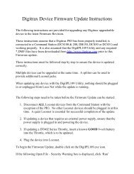
Diagram #4:Address Selection Flow Chart36
10.2 DT100IR Slot Following-"Training Mode"When a DT100IR detects that a loco address that is "in-use" on one of itsthrottles is being changed by another throttle or computer, it will "click" everytime it sees a remote throttle change its locomotive settings. If that locomotiveis in the display active throttle, its speed display will also show the changes.This is called slot following. This allows two DT100IR's to run a singlelocomotive with either throttle being able to send commands to the loco. Boththrottles will show the current speed and direction of the locomotive.Slot following is useful as a "training mode." The supervisor can "steal" alocomotive that is in a trainee's throttle & be able to "look over the trainee'sshoulder" or closely supervise that locomotive's control. The supervisor can gaininstant override control without having to physically "grab" the trainee's throttle.This lets you have unskilled visitors participating and enjoying operationswithout undue anxiety for either party.Slot following also allows a computer on LocoNet to run CTC & routing controlprograms with automated control over locomotives. The computer can controlspeed and stop engines automatically while letting the engineer with the throttlein his hand know what is happening.10.3 DB150 Loco Purging Strategy or Time Out!Sometimes when I plug my DT100IR back in it doesn't log back on to theengine (or engines) I was running before I unplugged. What should I do?The DB150 will automatically release or "purge" locomotives that are not underthe control of a throttle connected to LocoNet after about 3 1/4 minutes andmake them available for other throttles to select and run. This is a safety featurethat allows other throttles in the system to gain control of engines that may havebeen left running unattended by an engineer.By setting some option switches in the DB150 you can customize how yoursystem handles purging:1. The default is purge time=3 1/4 minutes (200 seconds).2. Purge time can be increased to 10 minutes (600 seconds) (OPSW13=closed).3. Purged locomotives can be set to stop when purged (OPSW15=closed).4. Purging action can be disabled completely (OPSW14=closed).See section 20.0 for information about setting DB150 option switches.37
11.0 Controlling Lights & FunctionsTo control Functions:1. Press the key once to enter the Light/Function control mode for the"display active" locomotive. The display will show "Fn:oo" with the "n"flashing to indicate that the function number of the function you wish tochange needs to be selected.2. Once you are in the "Fn:oo" mode, use one of the 5 keys with blue labels tochoose which function you want to change.3. Press the key again to change the Light or "F0" function. Each timethe key is pressed while in the "Fnoo" mode, the Light/F0 will changefrom OFF to ON or vice-versa. The display will show "F0:on" (Function0:on) for light ON & show "F0:oF" (Function 0: off) for light OFF.4. For F1, F2, F3, F4, press the key in the bottom row that corresponds to thefunction you want to control.5. To access functions F5 through F8, press and hold the key whilepressing the F5, F6, F7 or F8 keys to toggle between on and off for thefunction you choose.6. Once you are in function mode you can change as many functions as youwant to before returning to LOCO mode.To return to LOCO mode you have three options:1. Adjust either throttle knob,2. Press the or key, or3. Wait for the 6 second no-input time-out to elapseControlling Bell & Whistle SoundsF1 is labeled with a bell symbol to remind you that this is the preferred functionfor bell operation.F2 is labeled with a whistle to remind you that this is the preferred function forwhistle operation. F2 is a special non-latching function. This means that if F2is used to control a whistle or horn sound from the decoder, it will only soundwhen F2 is being held down. This lets you vary the length of time that thewhistle blows, just like the prototype.Note that for proper light operation, you must be sure that the operating mode(Standard 14 or Advanced 28/128 speed steps) of the decoder matches theoperating mode sent by the command station to that decoder. Empire Builderuses 128 speed step control by default. If you are using a decoders that do nothave 128 speed step capabilities see the Status Edit information in section 13.0.38
11.1 Controlling Functions On Consisted LocomotivesEven though a locomotive is part of a consist, you can still access its functionoutputs independently as follows1. Press and browse to the address of a locomotive that is a part of consist.2. Press again to set the loco to your throttle.2a. Consisted 2 digit short address. If the loco you want to change thefunctions on is a 2 digit short address, the display will show "aa:cn" (Addressnumber:consisted) to show that locomotive address aa is part of a consist &can't have its speed or direction changed. The throttle knob will NOT operate& the direction indicator will be unlit. However, the functions on thislocomotive address can be modified by pressing and proceeding with thenormal function control keystrokes outlined above!2b. Consisted 4 digit long address. In the case of a loco with a 4 digit address,when you press the the second time, the throttle will display "Se:L" (itwill appear to reject the address selection). Move either throttle knob or presseither direction arrow key and "-cn-" will be displayed in the first screenfollowed by a second screen with the consisted 4 digit loco address to let youknow that the loco selected is part of a consist. Press the key & proceedwith the normal function control keystrokes outlined above.12.0 Dispatching LocomotivesDispatching is a special feature incorporated in the LocoNet "language" to meetthe needs of operators that wish to enforce a strict discipline in how engineersaccess locomotives during an operating session. Dispatching also lets you runconsists with basic throttles that can't set up their own consists. It lets you havenewcomers run trains on the layout without giving them access to the entireoperation.To dispatch a locomotive using a the DT100IR1. Press to enter "address select," browse to the address you want todispatch2. Press to dispatch it, that's all there is to it!The dispatched train can be a single locomotive or a consist that was set up bythe DT100IR.Acquiring a "Dispatched" locomotive using a UT1 or UT21. Set the address selector switches to address "99" then press the "ACQ"button.2. The Status LED will light green showing that you now have control of thedispatched locomotive. (See Users <strong>Manual</strong> for UT1 or UT2 for completeinstructions).39
The TOP locomotive in a consist or MU can be dispatched to pass control of theentire consist to another throttle.There is only one Dispatch marked locomotive in the system at a time. TheDispatch marked locomotive will be acquired by the first throttle to requestit and press the ACQ key to set it to their throttle.13.0 Decoder StatusThe <strong>Digitrax</strong> system assigns status codes to each locomotive in the system.Status codes are made up of two digits and display in the form "aa:xy" for 2digit addresses and "St:xy" for 4 digit addresses.The left status digit "x" tells us the whether the decoder is new to the system,common, idle, or in-use. This digit is reserved for system usage and is notnormally user modified.The "x" status digit shows whether a particular address is selectable by throttlesand whether it is currently having its data refreshed by the command station.This controls the interlocking or sharing of locomotives between throttles."Refreshed" means that the command station is constantly repeating the lastcommand sent on the rails to a mobile decoder. This ensures that a mobiledecoder will be able to recover smoothly even if it has power interruptions dueto for example, dirty track.Table II: Loco STATUS Codes Left Digit ("x")Status Digit State Selectable? Refreshed?Value0y New selectable (default) not refreshed1y Common selectable refreshed2y Idle selectable not refreshed3y In-use not selectable refreshed5y Common not selectable consisted/refreshed7y In-use not selectable consisted/refreshedThe right status digit "y" tells us how many speed steps the decoder is using,whether it is an FX or not and whether it is a consist TOP. Refer to the tablebelow for the specifics. This "y" digit is the value that you can modify to selectthe speed step mode for a decoder.40
Table IIa: Loco STATUS Codes Right Digit ("y")Status Digit MeaningValuex0Normal 28 stepx2Baseline 14 stepx3128 stepx428 step FX decoder (enable advanced consisting)x5reservedx6reservedx7128 step FX decoder (enable advanced consisting)xb128 step & Consist TOPExamples: If a locomotive's status code is 03, it is new, selectable, refreshed &128 speed step operation. If a locomotive's status code is 52, it is part of aconsist, common, not selectable because it is not the TOP of the consist &operating in baseline 14 speed step mode.13.1 Status Editing a DecoderWhen you begin the address selection process by pressing the DT100IR'sLCD screen will show the address selected and the decoder status. If you wishto "status edit" the loco selected you must do so BEFORE pressing againand setting the loco selected to the throttle.2 Digit Short Address Status Display: The decoder status will display in theright hand side of the display for 2 digit short addresses4 Digit Long Address Status Display: Since we only have 4 digits in thedisplay, the data will be displayed in two screens. First you will see the 4 digitlong address for about 1 second then you will see "St:xy" which means StatusCode=xy (where x & y are the two digits of the status code as detailed in section14.0).To Status Edit a Decoder1. Press to enter address selection mode, the LCD screen will show theaddress selected and the decoder's status. You2. Press and the status code “xy will begin to flash.3. Use either throttle knob or the or keys to change the statusvalue. This value will be displayed in the right hand side of the displayor on the second screen as described above.4. Once the status code number you want is displayed in the right hand twodigits of the display, press to change the status code of thelocomotive and to set it to the display active throttle.5. If the loco was originally in-use, the throttle will become inactive withSE:L- in the display. A DT100IR throttle will not be able to edit the41
status of an in-use locomotive, it can only edit the status of a loco that isavailable for it to select.6. If the loco was common, idle or new at the start of editing, the newstatus value will be loaded & the throttle will be activated on thislocomotive when the key is pressed.A consisted loco address cannot have its status edited. To edit the status for aconsisted locomotive, the unit must be un-linked from the consist.13.2 Note for Lenz, Marklin, MRC & Arnold DecodersIf you have a decoder that does not understand Advanced 28/128 speed stepmode, you must "status edit" that locomotive to Standard 14 speed step modebefore running it with the DT100IR & the system. This tells the system tohandle this decoder as a 14 step decoder. It does not reprogram anything in thelocomotive. You will need to change the status code to a value of "x2", forexample "12", so that the system will operate those decoders in Standard 14speed step mode.14.0 Switch ModeTo change the position of a switch1. Press key until the SWITCH mode indicator at the top of the LCDscreen is on. The switch decoder address is displayed in the 3 right hand digitson the LCD screen. The right character in the LCD screen indicates the switchposition as follows:"t" indicates that the switch is "thrown" (diverging track selected)"c" indicates that the switch is "closed" (not turning out or diverging).If the "t" or "c" indicator is flashing it means that the LocoNet Command Stationdoes not know the current switch position.This display example shows Switch #2is in an unknown position.2. Use either throttle knob or orkeys to browse to the address of the switch you want to change. You canalso use the left throttle knob to set the 100's and the right knob to set the 1's.3. Once the desired switch address appears in the left 3 digits of the LCD, youwill see either "c" or "t" on the right digit of the display. If the "c" or "t" isflashing the command station does not have a known position for this turnout.Press either the "thrown" key or the "closed" key to select the turnoutposition you want.42
NOTE: When Operating a DT100IR on Big Boy system, if your DT100IRdetects that it is connected to system using a DT200 as the command station(Big Boy Starter Set) it will use the same 2 digit switch display mode as theDT200. Both left & right throttle knobs will only change the switch by 1count to a maximum of 128 or "c8."4. The switch you selected will change position from closed to thrown or viceversa.5. After commanding the switch "closed" or "thrown" the switch positiondisplay will stop flashing, since the command station now knows the currentswitch position.Note that the switch decoders in the system are accessible to all throttles orcontrol devices with switch control capabilities & are not reserved in-use to asingle throttle like locomotive decoders are.When you have finished your switch operations you can return to LOCOmode by:1. Pressing the key twice (skipping past MU mode ) or2. Wait for the 6 second no-input inactivity time-out to return the DT100IR tothe LOCO default mode.The next time you enter SWITCH mode , the DT100IR will rememberwhere you left off & start at the last switch address & position you accessed.15.0 Multiple Unit Operations:The DB150 command station offers two methods of consist control:1. The BASIC Consisting method is to reprogram all the locomotives in aconsist to the same address and run them off one throttle. In this case all thelocomotives must be headed in the same direction, head to tail, head to tail,head to tail. You probably won't use this method very often in youroperations because of its limitations. The Basic method is the only methodavailable to most basic command stations. We mention it here only becauseit is an option.2. The UniVersal Consisting method is handled by the command station andallows you to consist locomotives with any DCC format decoder as well as ananalog loco. The locomotives can be added to and deleted from the consist inany orientation, head to head or tail to tail. This method has the advantage ofbeing able to use all decoders in consists.You can add a locomotive to a consist in either direction and in any physicallocation in the train. When you send commands to the consist you use a singleaddress and the command station or decoders handle the rest of the commandsto the other locomotives in the consist. Since the address you will use to controlthe consist is not necessarily the address of the lead or head loco we have chosenthe term "TOP" locomotive for this special address. We always add or MU43
LINK a loco to the "TOP" loco of a consist. The "TOP" loco is special, in that itis the address that receives the speed & overall direction commands for theentire consist and all other locomotive's added or linked into the consist will becontrolled by running the "TOP" loco on a single throttle knob. The TOPlocomotive does not even have to be a physical loco on the track, it can be aphantom. The TOP loco is always defined as the loco on the Right ThrottleKnob at the time when the MU-Link is performed.Consists are controlled through the TOP locomotive & all locomotive's in theconsist will be common, in-use or idle based on the state of the TOP loco. Eachloco within a consist maintains its original Advanced 28/128 or Standard 14speed step mode setting. To run a loco in a consist with loadable speed tables,set the locomotive status for Advanced 28/128 speed step mode & program thedecoder to operate with the loadable speed table enabled. See your decodermanual for information about programming loadable speed tables. If you areoperating FX decoders, the Loadable table can be used in 128 step mode.A consist can be made common and then be selected and run by any otherthrottle. A consist can also be dispatched and picked up on a different throttle.See section 13.015.1 MU-Link: Adding a Locomotive To A ConsistTo set up a consist using your DT100IR throttle:1. Select and Set the address of the loco you want to be the TOP loco on theRight Throttle Knob "R". Remember that you can use any 2 digit shortaddress, 4 digit long address and/or an analog locomotive running on Address00 in any combination.2. Select and Set the address of the loco you want to consist to the TOP loco onthe Left Throttle Knob "L".3. Move the two locomotives into position. The locomotives can be headed ineither direction. They can be adjacent to each other in the train or one unitcan be the mid train helper or a pusher on the end of the train.4. Before consisting the locomotives together make sure that both are travelingin the SAME PHYSICAL DIRECTION ON THE TRACK. (The directionindicators may or may not match, the important thing is that thelocomotives are traveling in the same direction and are not pulling againsteach other.)5. Press the key until the MU mode indicator on the LCD display is lit.If both throttles are running 2 digit short addresses, the left-hand side of thedisplay shows the loco address active on the Left Throttle Knob "L" & theright-hand side of the display shows the loco address active on the RightThrottle Knob "R" (The TOP Loco). The LCD displays are slightly differentwhen performing MU operations with 4 digit long addresses .In this case allthe operations are performed with the same key-strokes & have the samemeanings as for 2 digit short addresses. When you enter MU mode, before44
you add or delete a loco from the consist, if either throttle has a 4 digit longaddress, then the LCD display will show "oooo" with the MU indicator lit.6. Press the key to MU LINK the locomotives. That's it! The Left Throttledirection indicator will go off. The Right Throttle Knob "R" will nowcontrol the speed & direction of both locomotives in the consist.After you have MU LINKED the locomotives, if the Left Hand Throttle (LinkedLocomotive) is a 4 digit long address the display will show ":SEL". If you turnthe left throttle slightly, the display will briefly display "-cn-" (indicating that the4 digit long address that was in the Left Hand Throttle is now part of a consist)and then will display the 4 digit long address of the consisted loco in the LCDdisplay.You can access the functions of the any loco in the consist by selecting theconsisted loco to a throttle and using the function keystrokes outlined in section12.1. You will not be able to change the speed or direction of any loco that ispart of a consist but is not the TOP loco while it is consisted.Once a consist is set up & linked to the TOP locomotive, this TOP loco can bereleased & selected to run from either throttle. The consist can also be selectedand run on another throttle or it can be dispatched to another throttle.Nested Consist LinkingThe loco that was selected in the Left Throttle "L" to be linked can itself be the"TOP" loco of a consist. When it is MU linked to the current Right Throttle"TOP" loco it will become a "nested" consist. In this case the whole nestedconsist is linked & itself will be part of the new consist.15.2 MU UNLINK: Breaking A Loco Out Of A ConsistThis example shows 2 digit short address loco#36 consisted & selected.1. Select the loco address that you want toremove from a consist on the Left Throttle"L". For 2 digit short addresses the displaythe loco address on the left and will show "cn" on the right side of the LCD,confirming this loco is part of a consist. For 4 digit long addresses thedisplay will flash "-cn-" followed by the 4 digit number, with the DIR & EXPindicators unlit.2. Press the key until the MU mode indicator on the LCD screen is lit.3. Press the key to MU UNLINK the locomotive. The unlink is complete.The Left Throttle "L" automatically becomes active with the loco you justunlinked! If you unlink while the consist is moving, the unlinked loco will bebroken out of the consist at the same speed & direction that it was moving in theconsist. You can uncouple and run the unlinked loco as an independent locoagain!45
15.2.1 Nested Consist UnlinkingThe loco that is selected in the Left Hand Throttle to be unlinked can itself bethe "Top" loco of a nested consist that was linked into the current Right throttle"Top" loco. In this case the whole nested consist is unlinked & returned to theLeft Throttle as a consist.15.3 MU of Mismatched LocomotivesIf all the locomotives in the consist have performance characteristics that areclosely matched, you can run all the consisted locomotives in 128 step mode. Ifthe units are completely mismatched (for example if you are running an Athearnwith a Kato), then we recommend programming the decoders using the UserLoadable Speed Table (See section 19.5) & running the DT100IR in the 28 stepmode to achieve better speed matching of locomotives in the consist. This letsyou speed match the 28 step operation of each locomotive to a given referencelocomotive, so when they are consisted they will run well together. If you wantto consist with a conventional analog locomotive, use the analog locomotive asthe reference locomotive & match the DCC locomotives to it using the UserLoadable Speed Table.If you are using FX type decoders then you can use the Loadable Speed tables in128 step mode for really superior speed control & matching in MU's or consists.16.0 DT100IR Configuration OptionsThe DT100IR has an individual throttle OPTION mode that lets you customizeyour throttle. The options are assigned as hexadecimal numbers representingcombinations of options as shown in the tables below. The default values aregenerally satisfactory for most operations.NOTE: It is recommended that all locomotives assigned to this throttle bereleased before you change any options.1. Unplug the DT100IR from the network. Press and hold the "SEL/SET"button and plug the DT100IR back into the network. The display will showthe Primary Throttle Option Screen "oP:01" (default). This display willappear for approx. 5 seconds if no action is taken, if no action is taken after5 seconds, the DT100IR will return to "RUN" mode2. 2. While "oP:nn" is still in the display, use the throttle knobs "R or L" tomodify the Primary option value according to the following table:46
DT100IR Primary Option ChoicesPrimaryOptionValueOptions EnabledBallistic Tracking FastClockDisplayKey &KnobClicksRun/StopLocal/Global00 No No Yes Local01 Yes No Yes Local02 No Yes No Local03 Yes Yes Yes Local04 No No No Local05 Yes No No Local06 No Yes Yes Local07 Yes Yes No Local10 No No Yes Global11 Yes No Yes Global12 No Yes No Global13 Yes Yes Yes Global14 No No No Global15 Yes No No Global16 No Yes Yes Global17 Yes Yes No Global3. Save the primary throttle option code by pressing the key. The displaywill then show the Secondary option code screen "oS:23" (default).1. The Secondary option code screen "oS:23" (default) will appear for approx.5 seconds, if no action is taken after 5 seconds, the DT100IR will return to"RUN" mode2. Use the throttle knobs "R or L" to modify the value for the secondaryoptions according to the following table. The Secondary option codesshown allow you to override the system default NEW decoder type whenselecting with this DT100IR.47
DT100IR Secondary Option ChoicesSecondary Throttle Default For NEW Decoder TypeOption Valuex028 Stepx214 step decoderx3128 step decoderx428 step FX decoderx7128 step FX decoderx8Disable NEW type override feature2xRadio disabled4xInfrared disabled6xAll tetherless disabled8xDisable power save1. To save the secondary option code press . Throttle will now show thethrottle ID number. Make sure the ID is unique to the throttles used on thissystem. Use the throttle knobs "R or L" to modify the value of the ID. Tosave the ID code press..2. The display will then show the Radio Frequency channel " rf :00"(default). This sets the channel for either Infrared or Radio operation if it isinstalled.Note: If no keys are pressed, the time-out for Throttle Option Mode is 12seconds & the DT100IR will go to idLE if you do not press any keys within thatamount of time.17.0 Infrared Tetherless Operation of DT100IRThe DT100IR in your Empire Builder set comes "InfraReady". With theaddition to the system, of a UR90 Infrared receiver or a UR91 Radio/Infraredreceiver, the DT100IR can be used as an Infrared tetherless walk around throttle.A 9 volt battery, in the throttle, is nessessary to operate the DT100IR"Tetherless". Due to the nature of the Infrared signal more than one receivermay be necessary for optimal performance.When a DT100IR is plugged into a working LocoNet, it will verify that at leastone infrared capable receiver is present. The DT100IR will then assume thecurrent Network ID that the infrared capable receiver(s) are set to, andsubsequently allow itself to revert to infrared operation when it detects asubsequent LocoNet disconnection.48
17.1 LocoNet ConnectionOn connection to a LocoNet that has compatible infrared capability, theDT100IR LCD display will flash the infrared status code “rA:0n” the number“n” signifies the LocoNet ID being used by all receiver’s on the system it hasplugged into and will be identifying itself with. The display will then revert tonormal DT100 tethered operation displays and actions. If the system does nothave a UR90 or equivalent device, the DT100IR will not display the “rA:--“message to show that it cannot operate “Tetherless” on that system and thus notallow the infrared to be active when untethered.17.2 Display power downWhen the DT100IR has connected to a LocoNet and received the LocoNet IDnumber it will allow tetherless operation of locomotives that have been selectedinto either throttle knob. If an untethered DT100IR detects no user throttleactivity for about 3 minutes it will enter Power Saver mode and display on theLCD the infrared status code “r- PS” until a throttle or key action restoresnormal activity and displays. If the DT100IR has a locomotive assigned to it andis in Power Saver Mode, it will continue to “check in” with the system every 60seconds telling the system “Hey I’m still here”. This keeps the system fromreleasing that locomotive back to “common”. The direction LED’s of activethrottles may blink every 1.5 seconds when the DT100IR is checking to see ifany new key or encoder input has been made. It may be most convenient to holddown either the or key to signal the unit to exit from power saver mode.You can use the Secondary option to turn off Power Saver mode, see section17.0.If you wish to have the infrared throttle enter the lowest power use “idLE” stateof a normal DT100, then you can connect it to a LocoNet in sleep mode. If theLocoNet is in sleep and has battery saver capability then the DT100IR can takeall its power indefinitely from the LocoNet. Alternatively, you may reset theDT100IR by simultaneously pressing the , and keys , as detailed inthe DT100 instructions. Once the DT100IR is reset it remains “idLE” andcannot become an active infrared throttle until it has been reconnected to ainfrared capable LocoNet and has an active address selected. Of course, youmay simply remove the DT100IR battery to power down an untetheredDT100IR.If you use Power Saver mode then the DT100IR’s local Fast clock copy willdeviate from the System value. It will resynchronize with the system whenreconnected.49
17.3 LocoNet ID changeIn normal operations a DT100IR will accept and use the LocoNet ID offered bythe compatible infrared receiver(s) it may see when connected to the network.To allow a LocoNet to be changed to a different ID number, to allow forexample 2 clubs to have layouts at the same show, the DT100IR may be used tochange the LocoNet ID number of one of the independent LocoNet systems.To change a LocoNet ID number:1) Disconnect a DT100IR from the LocoNet that you wish to modify the ID.2) Press and hold down the MODE/DISP key on the DT100IR and thenreconnect the unit to the LocoNet. This key being active upon reconnect enablesthe DT100IR to be allowed to modify the system ID.3) Release the MODE/DISP key. The DT100IR will flash up the currentinfrared ID# “rA:0n”, where the “n” digit shows the current LocoNet ID. UseRIGHT HAND THROTTLE to change the ID digit “n” to that desired, in therange 0 to 7, and then press the SEL/SET key to set the system to the newID.4) Be sure to reconnect any DT100IR that is going to be used on this systemback to the system so it can adopt the new ID number and be able to access thenew system ID.If you add a new UR90 or UR91 to the system and are using a LocoNet ID otherthan the initial default value of 0, you need to re-synchronize the ID's in all theUR90's and UR91's following the outlined steps above with a new ID for thewhole systemIf you are operating in a large group or meet with several differentLocoNet systems nearby, be sure to issue a new and unique ID to eachsystem before beginning operations.17.4 “Tetherless” OperationSelecting a LocomotiveWhile tetherless, the DT100IR operates as a one-way transmitter and uses itscable connection to establish initial locomotive address selection. The DT100IRmust be plugged into LocoNet to select an available locomotive address.After a DT100IR has selected a locomotive, it may then be unplugged from thenetwork and will automatically revert to infrared operation for all subsequent,speed, direction, function and turnout commands.Releasing a LocomotiveWhen working untethered with an active address in the LCD display, if theSEL/SET key is pressed the locomotive address will immediately be released ascommon in the system and that throttle will become inactive. To re-select thislocomotive you will then need to reconnect to the LocoNet. The DT100IR will50
automatically reselect that locomotive when the DT100IR is connected to thenetwork providing that the status of that locomotive remains in commonMultiple Unit OperationsConsists may be assembled and broken up in the normal fashion while theDT100IR is connected to LocoNet, however, the M.U. function is locked outwhile the DT100IR is being used Tetherless. Once a consist is made up, it maybe operated normally using the DT100IR “Tetherless”.Operations Mode ProgrammingOperation Mode Programming or OPS mode will work only while the DT100IRis connected to LocoNet.Service Mode ProgrammingThe DT100IR must be connected to LocoNet to use it’s Service ModeProgramming Mode.Switch ModeThe DT100IR will operate in the “Switch” Mode while “Tetherless”. It canthrow switches and routes using the “t” and “c” buttons in the normal manner.Ballistic TrackingWhile running “Tetherless” Ballistic Tracking will feel slightly different thanwhile connected to LocoNet.Fast ClockWhen using the Fast Clock option, the DT100IR will keep track of and displayFast Time based on what the Fast Time was the last time the DT100IR wasconnected to LocoNet. If the Fast Time is edited by someone else connected tothe network, the DT100IR will not see this change until it is plugged intoLocoNet at which time it’s display will be updated.17.5 Battery “Fuel Gauge”The DT100IR continually checks the voltage of the battery while running“Tetherless”. If it detects a voltage in the questionable range, around 6.8 volts,the DT100IR will beep twice in about one second and display “bt:nn” on theLCD. The “n” is the number of times the warning has sounded. The warningwill continue every 5 min. until the battery is changed. The display willdisappear when any control is activated. Don’t Panic when this warningappears. The DT100IR will continue to function normally for an extendedperiod of time depending on the type battery in use. 9 volt alkaline batteries arenearing the end of their life at this voltage, but 7.2 volt NiCad rechargeablebatteries may still have lots of life remaining. Experience will determine howlong your DT100IR will operate after the warning has sounded. The counter inthe display is a useful tool in determining how long your battery will last. The51
attery can be “Hot Changed” while the DT100IR is plugged into LocoNet andwill not lose any locomotive assignments.17.6 Infrared OverrideA value of "23" entered as the Secondary Option for a DT100IR will disable theRF option. A value of "03" will re-enable the RF or infrared option. This maybe changed any time the DT100IR is initialized.Bottom DigitSecondaryOption Valuex0x2x3x4x7x8Top digitSecondaryOption Value0x2x4x6x8xDT100IR Secondary Option ChoicesThrottle Default For New Decoder28 Step14 step decoder128 step decoder28 step FX decoder128 step FX decoderDisable NEW type override featureTetherless Features controlRadio with power saverRadio disabledInfrared disabledAll tetherless disabledDisable power saveExample: “oS:23” means 128 step new locomotive, infrared and Power Saverenabled. This is the normal factory default.17.7 Keyboard Lock OutWhile the DT100IR is being used "Tetherless", there are occasions when youmay want to disable the throttle keyboard to prevent accidental commands beingsent to the railroad.Example: Your train is in a siding waiting for another train to pass. You put yourthrottle in your pocket and go take a break. By locking the keyboard, you willnot be able to accidentally start your train if you bump your throttle and pressthe "Plus +" key.52
To lock the keyboard on your DT100IR, simply press both the "PLUS +" andthe "MINUS -" keys at the same time. The throttle will display "Locd" in thedisplay and none of the controls will function.To un-lock the keyboard simply press both the "PLUS +" and the "MINUS -"keys at the same time again. This will return the throttle to normal operation.Plugging the throttle into LocoNet will also unlock the throttle.18.0 Programming and ConfigurationYour DCC Decoders have many different Configuration Variables (CV's forshort) that let you set up a different set of operating characteristics for eachdecoder installed in each locomotive.Each of these CV's controls a characteristic of the decoder. See Table III for alist of the most commonly used CV's and their meanings. Each decoder comespre-programmed from the factory with the default settings outlined in yourdecoder manual. You can change your decoder's performance characteristics bychoosing from among the CV's and setting up each one independently. Each ofthese CV's can be set up when your command station is in the programmingmode or by using the <strong>Digitrax</strong> PR-1 Computer Programmer & your PC. TheCV's are remembered in the decoder until it is reprogrammed to a new value.Please refer to your Mobile Decoder <strong>Manual</strong> for a complete listing of the CV'ssupported by each decoder.It is a good idea to run your decoders with the default values that come preprogrammed in your decoders until you get used to the system & what it can dofor you. Then you can begin customizing. Initially, we recommend that youkeep deceleration values small. This will let you adapt to the delays indeceleration you have programmed without crashing your valuable locomotives!The DB150 command station sends programming information to the decodersthrough the rails. This information is sent as a broadcast message to anydecoder that is listening. This means that you could reprogram all thelocomotives on the layout with one keystroke. (See section 4.2 SeparateProgramming Track)When the DB150 receives a programming command from any throttle on theNetwork, it shuts down any boosters connected to it and stops all locomotives.The DB150 then sends the programming command to any decoder on the trackdirectly connected to the DB150 command station. The DB150 beeps once toindicate that it has sent the programming command. Track under the control ofother expansion boosters will not receive the command.53
18.1 How to Program 2 Digit Addresses1. Be sure that only the loco you want to program is on the programmingtrack.2. Press and hold then press at the same time to enter programmingmode.3. The DT100IR's green PROG indicator will come on, letting youknow that you are in programming mode.4. The LCD will flash the word "PagE", letting you know that you are inpaged mode. This is the preferred method of programming for all <strong>Digitrax</strong>decoders. If your display does not show "PagE", press the FUNC key tomove through the programming methods until "PagE" shows in yourdisplay.5. The LCD will display AD:--. Turn the Right Throttle knob "R" on theDT100IR until the address number you want to use for the loco is displayedin the right hand side of the LCD screen.6. Press the key to "SET" the address of the decoder to the value showingin the right side of the display. If programming was successful, theDT100IR will flash "Good". The DT100IR will then display AD: followedby the two digit address you just programmed to the decoder.7. Press and hold then press at the same time to exit programmingmode. The LCD will Show SE:L-.8. To select and run the loco, turn the left or right throttle 1/4 turn to activateit, press the key, dial up the address you want to run and press thekey again to SET the address to the throttle.9. After you do any programming, the first time you select a loco to run, thesystem will turn off track power. Simply press and hold the key thenpress the key while continuing to hold the Run/Stop Key. Release bothkeys when the system beeps and you see the lights on the DT100IR changefrom steady ORANGE.18.2 How to Program Four Digit AddressesAutomated Programming of CV18 & CV17 To Set Up 4 Digit Addresses1. Place the locomotive with 4 digit capable decoder on the programmingtrack.2. Enter Program Mode by holding down & pressing at the sametime. If your display does not show "PagE", press the FUNC key to movethrough the programming methods until "PagE" shows in your display.3. Use the DT100IR's Left Throttle Knob "L" to select CV18 in the left 2digits of the display.4. Press the key. This starts the 4 digit sequence. Before you make anychanges, press the key again to force the DT100IR to look at both V17and CV18 at the same time. All four digits in the display will be flashing.54
5. Use the two throttle knobs to choose the address you want to program intothe decoder on the programming track. The Left knob changes 100's &1000's and the and the right knob changes 10's & 1's.6. To program the 4 digit address to the decoder press the key and theDT100IR will flash "Good" if the programming was successful followed bydisplaying the four digit address programmed.7. To exit four digit address programming mode, press the key. TheDT100IR will return to regular 2 digit programming mode.8. To activate the four digit address you just programmed, you will have toprogram CV29, the configuration register variable so that the decoderknows it is supposed to use the four digit address. <strong>Digitrax</strong> recommendsthat CV29 be set to 26 to give you four digit addressing, 128 speed steps,analog mode conversion enabled. For other options check the CV29 tableof values/features below.9. You can program as many CV's and their values as you want in a session.When you are finished, press and hold then press at the same timeto exit programming mode. If the direction indicator lights on the DT100IRboth change to orange, simply press and hold the key then press thekey while continuing to hold the Run/Stop Key. Release both keys whenthe system beeps and you see the lights on the DT100IR change from steadyORANGE.18.3 CV29 Configuration Register ProgrammingThe Configuration Register CV29 is used for setting up more than onedecoder characteristic. To determine which value to enter in CV29, checkthe table below or check your decoder manual for more information andother options. These are some of the common hexadecimal (hex) valuesused in the Configuration register (CV #29) & their meaning.Value in CV29 Features Controlled(in hex)Speed Steps(Standard orAdvanced)55Addressing00 14 (Standard) 2 digit No02 28/128 (Advanced) 2 digit No04 14 (Standard) 2 digit Yes06 (Default) 28/128 (Advanced) 2 digit Yes16 Enable Loadable 2 digit YesSpeed Table20 14 (Standard) 4 digit No22 28/128 (Advanced) 4 digit No24 14 (Standard) 4 digit Yes26 28/128 (Advanced) 4 digit Yes36 Enable LoadableSpeed Table4 digit YesAutomaticAnalogConversion
Note that with <strong>Digitrax</strong> Standard Decoders (non FX decoders), if 128 speedsteps are sent by the command station then the 14/28 speed step & Loadablespeed table selections are not used.18.4 How to Program Other Configuration VariablesThere are many different CVs that have been defined to handle manycharacteristics you might want to use for your locomotives. Table III belowcontains a list of the CVs used most often. Your decoder manual has a completelisting of CVs, what they do and suggested values for each CV.1. Be sure that only the loco you want to program is on the programmingtrack.2. Press and hold then press at the same time to enter programmingmode.3. The DT100IR's green PROG indicator will come on, letting youknow that you are in programming mode.4. The LCD will flash the word "PagE", letting you know that you are inpaged mode. This is the preferred method of programming for all <strong>Digitrax</strong>decoders. If your display does not show "PagE", press the FUNC key tomove through the programming methods until "PagE" shows in yourdisplay.5. The LCD will display AD:--.6. Turn the Left Throttle knob "L" on the DT100IR until the CV # you want toprogram appears on the left side of the LCD.7. Turn the Right Throttle Knob "R" until the value you want to program intothat CV appears in the right side of the LCD.8. Press the key to set the values selected.9. You can program as many CV's and their values as you want in a session.When you are finished, press and hold then press at the same timeto exit programming mode. If the direction indicator lights on the DT100IRboth change to orange, simply press and hold the key then press thekey while continuing to hold the Run/Stop Key. Release both keys whenthe system beeps and you see the lights on the DT100IR change from steadyORANGE.56
Table III: Most Commonly Used CV'sCV # Used For Value rangeAd(01) Loco 2 digit short address0-99 decimal, "A0 -C7"mixed mode02 Start voltage (Vstart) 0- FF hexadecimal03 Acceleration rate 0-1F hex04 Deceleration 0-1F hex06 Mid-point voltage (Vmid) 0-FF hex17 Loco 4 digit long address high C0- FF hex18 Loco 4 digit long address low 0-FF hex19 Advanced consist address 0-7F hex29 Configuration register See Table IVCV's 65 to 95 control the 28 step "Loadable Speed Table" function & TableV lists the actual usages.18.5 User Loadable Speed TablesLoadable speed tables let you customize the throttle response of individualdecoders & locomotives by defining your own personal throttle response curvefor each decoder in your fleet.There are two types of loadable speed tables: One is a three step curve and theother has 28 speed step data entries that let you "draw" an arbitrary "powercurve" with a resolution of 1/2%, from stop to full-speed. The shape of thiscurve defines the "feel" of the decoder throttle response. Once you set up thisthrottle response curve for a particular DCC loco, you can scale the actual speedset by the throttle by using the forward & reverse trim value which acts like a"volume control." For example, using forward & reverse trim, you can changethe maximum forward speed from 45 scale mph to 80 scale mph without havingto reload the entire 28 step table. Changing the forward or reverse trim valueswill scale or multiply all the values used in the table, in the correspondingdirection, by the amount desired. Using different forward & reverse trim valuesallows different forward & reverse speeds. The trim value can increase the tablevalues from 100% to 200% with 1% resolution, or down from 100% to 2% with1% resolution. All the table values are non-volatile & are remembered when thepower is off.With loadable speed tables, you can "speed match" locomotives that you wouldlike to use in a consist even if their operating characteristics are very different.57
To Program A 28 Step Loadable Speed Table:1. Be sure that only the loco you want to program is on the programmingtrack.2. Press and hold then press at the same time to enter programmingmode.3. The DT100IR's green PROG indicator will come on, letting youknow that you are in programming mode.4. The LCD will flash the word "PagE", letting you know that you are inpaged mode. This is the preferred method of programming for all <strong>Digitrax</strong>decoders. If your display does not show "PagE", press the FUNC key tomove through the programming methods until "PagE" shows in yourdisplay.5. The LCD will display AD:--.6. Turn the Left Throttle knob "L" on the DT100IR until the "65" appears onthe left side of the LCD.7. If you want to use a 3 step table, just program Vstart CV02, VmidCV06 & V-max CV94.8. Turn the Right Throttle Knob "R" until the value you want to program intoCV65 appears in the right side of the LCD.9. Press the key to set the values selected.10. Turn the Left Throttle Knob until "66" appears in the loft side of the LCD.Turn the Right Throttle Knob until the value you want to program for CV66shows in the right side of the LCD. Press SEL/SET to program CV66 to thechosen value.11. Continue programming all CVs from 65 through 96 as above.12. Program CV29 to a value of 10-19 or 30-39 (see the table above todetermine the value you want to use.13. You can program as many CV's and their values as you want in a session.When you are finished, press and hold then press at the same timeto exit programming mode. If the direction indicator lights on the DT100IRboth change to orange, simply press and hold the key then press thekey while continuing to hold the Run/Stop Key. Release both keys whenthe system beeps and you see the lights on the DT100IR change from steadyORANGE.58
Table V: Example Loadable Speed TableUsage CV # DT200HEX DataSee Note 1LenzRegisterSuggestedSettingDECIMALPage 17=PLKick Start CV65 01 1 1Forward Trim CV66 80 2 128Step 4 value CV67 0A 3 10Step 5 value CV68 0E 4 14Page 18=PL6Step 6 value CV69 12 1 18Step 7 value CV70 16 2 22Step 8 value CV71 18 3 24Step 9 value CV72 1c 4 28Page 19=PL6Step 10 value CV73 20 1 32Step 11 value CV74 24 2 36Step 12 value CV75 28 3 40Step 13 value CV76 2c 4 44Page 20=PL6Step 14 value CV77 32 1 50Step 15 value CV78 36 2 54Step 16 value CV79 3c 3 60Step 17 value CV80 40 4 64Page 21=PL6Step 18 value CV81 46 1 70Step 19 value CV82 4c 2 76Step 20 value CV83 52 3 82Step 21 value CV84 5A 4 90Page 22=PL6Step 22 value CV85 60 1 96Step 23 value CV86 6A 2 106Step 24 value CV87 72 3 114Step 25 value CV88 7E 4 126Page 23=PL6Step 26 value CV89 88 1 136Step 27 value CV90 94 2 148Step 28 value CV91 A2 3 162Step 29 value CV92 b2 4 178Page 24=PL6Step 30 value CV93 c6 1 198Step 31 value, CV94 dA 2 218Reverse Trim CV95 80 3 128Configuration Register CV29 16 5 22Page Register None None PL6=Page register 159
Notes for Table V:1. The DT100IR uses hexadecimal numbers for the data to be stored in all CV'sexcept the address CV (CV#1). Table VI shows how hexadecimal numberscorrespond to regular decimal numbers.2. Kick Start gives a short voltage "kick" when you start the locomotive decoderfrom 0 speed. A value of 0 turns this OFF. Experiment with values for aparticular installation to find the best compromise.3. Forward Trim (CV66) & Reverse Trim (CV95) values of 128 (80 Hex) willyield a scaling of 100%. The same effect will occur if the value 0 or 1 isloaded for Forward or Reverse Trim, i.e., Multiply by exactly 1. A Trimvalue of 255 (FF Hex) will give 200% scaling of the table entry value.4. A scaled table value of 255 (FF Hex) represents 100% applied motor voltageor full speed. A value of 128 (80 Hex) represents 50% applied motor voltage,i.e., the actual table step entry is multiplied by the appropriate Trim value toyield the final scaled table value that defines the voltage to apply to themotor.5. The Steps defined in the table are for the NMRA 28 step mode. Step 4 is thefirst motion step in the 28 Speed step system. Step 31 is the "full throttle"speed step. When configuring the decoder to run 14 step mode, only everysecond entry is used, the decoder automatically uses the correct data value.6. The suggested data values given in the table will give a throttle responsecurve that most US users are comfortable with. The data values can bemodified to suit your individual preferences.Note that if the Configuration Register is set up with the User Loadable SpeedTable flag SET (CV29 set to 16 or 36) to enable the Speed Table, the VSTART& VMID values are not used to by the decoder when calculating LoadableSpeed Table values.Many <strong>Digitrax</strong> customers have asked us why we can't formulate tables like thisone for the specific locomotives that they are running. The reason for this is thateach & every locomotive is different. If we bought 5 identical brand newlocomotives today & put them on the test track, we would probably find thatthey do not all run exactly the same way. And, as time goes on & we run theselocomotives for different amounts of time under different sets of circumstancesthey will probably change even more. It's really best to start with the defaulttable shown & work with your own equipment to customize it for your ownpreferences. If you are planning to do a lot of customizing, the PR-1 is probablyan easier solution for setting up loadable speed tables.60
Table VI: Decimal to Hexadecimal Conversion ChartDEC HEX DEC HEX DEC HEX DEC HEX DEC HEX DEC HEX DEC HEX00 00 39 27 78 4E 117 75 156 9c 195 c3 234 EA01 01 40 28 79 4F 118 76 157 9d 196 c4 235 Eb02 02 41 29 80 50 119 77 158 9E 197 c5 236 Ec03 03 42 2A 81 51 120 78 159 9F 198 c6 237 Ed04 04 43 2b 82 52 121 79 160 A0 199 c7 238 EE05 05 44 2c 83 53 122 7A 161 A1 200 c8 239 EF06 06 45 2d 84 54 123 7b 162 A2 201 c9 240 F007 07 46 2E 85 55 124 7c 163 A3 202 cA 241 F108 08 47 2F 86 56 125 7d 164 A4 203 cb 242 F209 09 48 30 87 57 126 7E 165 A5 204 cc 243 F310 0A 49 31 88 58 127 7F 166 A6 205 cd 244 F411 0b 50 32 89 59 128 80 167 A7 206 cE 245 F512 0c 51 33 90 5A 129 81 168 A8 207 cF 246 F613 0d 52 34 91 5b 130 82 169 A9 208 d0 247 F714 0E 53 35 92 5c 131 83 170 AA 209 d1 248 F815 0F 54 36 93 5d 132 84 171 Ab 210 d2 249 F916 10 55 37 94 5E 133 85 172 Ac 211 d3 250 FA17 11 56 38 95 5F 134 86 173 Ad 212 d4 251 Fb18 12 57 39 96 60 135 87 174 AE 213 d5 252 Fc19 13 58 3A 97 61 136 88 175 AF 214 d6 253 Fd20 14 59 3b 98 62 137 89 176 b0 215 d7 254 FE21 15 60 3c 99 63 138 8A 177 b1 216 d8 255 FF22 16 61 3d 100 64 139 8b 178 b2 217 d923 17 62 3E 101 65 140 8c 179 b3 218 dA24 18 63 3F 102 66 141 8d 180 b4 219 db25 19 64 40 103 67 142 8E 181 b5 220 dc26 1A 65 41 104 68 143 8F 182 b6 221 dd27 1b 66 42 105 69 144 90 183 b7 222 dE28 1c 67 43 106 6A 145 91 184 b8 223 dF29 1d 68 44 107 6b 146 92 185 b9 224 E030 1E 69 45 108 6c 147 93 186 bA 225 E131 1F 70 46 109 6d 148 94 187 bb 226 E232 20 71 47 110 6E 149 95 188 bc 227 E333 21 72 48 111 6F 150 96 189 bd 228 E434 22 73 49 112 70 151 97 190 bE 229 E535 23 74 4A 113 71 152 98 191 bF 230 E636 24 75 4b 114 72 153 99 192 c0 231 E737 25 76 4c 115 73 154 9A 193 c1 232 E861
18.6 Operations Mode ProgrammingOperations mode lets you program CV's in DCC locomotives equipped withEPF decoders while they are on the mainline. A typical use for OPS modeprogramming would be to change the acceleration rate (CV03) or thedeceleration rate (CV04) of your locomotives to simulate the weight and brakingcapability of the train to compensate for changing the number of cars and powerunits. You can also modify the FX parameters in CV49 through CV53 andCV62 and CV63.Operations mode programming can be performed by any DT100IR at any timesince the throttles are not competing for usage of the single programming track.How to use Operations Mode Programming1. Select the DCC loco address that you want to program and set it to eitherthrottle. Be sure that the address you want to program is "display active" onthe throttle when you enter programming mode.3. Use your DT100IR to enter Operations Mode Programming press and hold& then press at the same time. Release both keys when the proglight comes on.4. Press the key to scroll from "PagE" to "phys" to "dir" to "OPS"programming mode. The DT100IR display will show "OPS."3. Use the Left throttle knob "L" to select the CV you want to modify. Use theRight throttle knob "R" to select the value you wish to enter for the selectedCV.4. When you have selected the CV and its value press either the or keyand the selected CV and its value will be programmed to the DCCLocomotive address that was in the active throttle when programming wasentered.5. If you get a "bUSY" message in response to a or key press, thesystem is temporarily busy and you must to press the key again until you geta "Good" response.6. To return to LOCO mode from Operations mode programming, simplypress & simultaneously again to return the DT100IR to LOCO mode.Changing The DCC Decoder Address With Ops Mode ProgrammingOperations mode programming cannot be used to make changes to decoderaddresses CV01, the 2 digit address of any mainline loco at any time.Operations mode programming cannot be used to make changes to a four digitaddress (CV18 & CV17) of any mainline loco at that was addressed by its four62
digit long address when you entered programming mode. If you were using 4digit long addressing to run a loco on the mainline and you try to program a new4 digit address to the loco, the DT100IR will display a "FAIL" message whenyou try to use the to write the new 4 digit long address.You can use operations mode write a new 4 digit long address (CV18 & CV17)to the decoder, as long as it was being accessed using its 2 digit short address(CV01) when you entered programming mode. If you want to use OPS mode toprogram a 4 digit long address in this case, once you select CV18, press thekey when CV18 is selected and use the throttle knobs to dial up the 4 digitaddress you wish to program. When the new 4 digit long address is in thedisplay, press the key to write the flashing 4 digit long address in thedisplay into the mainline loco.63
Diagram #5: Fast Clock Editing Flow Chart64
19.0 DT100IR Fast ClockMany operators use a fast clock during operating sessions to simulateprototypical operations. Traditionally, this clock is on the wall and is set up torun at a faster than normal rate. The DT100IR has its own networked fast clockon all the DT100IR's in your LocoNet system. You can use this feature withboth DB150 and DCS100 command stations (Chief Set) and DT200 commandstations (Big Boy Sets).The Fast clock display is a 4 digit 24 Hour format clock. You can tell whenyour DT100IR is displaying the fast clock when you see the DT100IR's colonblinking.You can set up your DT100IR so that its default display is either the fast clockdisplay or the LOCO mode display. When there is no activity on your DT100IRfor more than about 6 seconds, the DT100IR will revert to the default displaythat you set up in the DT100IR. When you press any key or turn either throttleknob, the default display will change to reflect the current throttle activity. YourDT100IR was shipped to you with LOCO mode as the default display. Seesection 17.0 for information about making the fast clock your default displayand follow the instructions in this section for setting your clock.If you have more than one DT100 series throttles on a Big Boy set, theDT100IR's will automatically synchronize their Fast clocks, even though the BigBoy's DT200 command station was not originally set up with a Fast clock. Thisis an example of the upgradeability benefits that a true Peer-to-Peer networkarchitecture offer. With LocoNet you have the ability to simply add or "layer"new functional features onto your existing LocoNet system with no impact onexisting hardware.Any DT100 series throttle you plug in to your LocoNet system will update itsfast clock time and rate to be synchronized to the rest of the system a couple ofseconds after it is connected after being "idLE".Each DT100 can be set up with its own alarm. When the current fast clock timematches the private alarm time set in any DT100, then that DT100 only willbeep and flash up the message "ALAr" to indicate that the alarm time haselapsed. The alarm time is of the same 24 Hr format as the fast clock.The fast clock rate for the Fast clock is user selectable from 1:1 to 100:1 in stepsof 1, and the range values of 4:1 to 8:1 are often used.Freezing the Fast ClockSetting the clock rate to 00 will STOP or freeze the fast clock in the wholesystem at the currently displayed time. The time will re-start when a new nonzerorate value is selected.65
The current fast clock time, fast clock rate and the DT100IR alarm time can bechanged by using the Edit mode. Refer to Diagram 5 for a flow chart of the fastclock editing key strokes.To Edit Fast Clock Time, Rate & Alarm time.Note: Fast Clock cannot be edited while "Untethered"1) From LOCO mode, press the key to change to SWITCH mode.2) Press the key to change from SWITCH mode and enter EDITOR modes.If you have routes enabled in the system, you will enter the Route Editor andthe first display you will see is "rt:01". If you do not have routes enabled, youwill by pass this step and go straight into the Clock Editor.3) If routes are enabled you will need to press the key again to change fromthe Route Edit mode to the Fast Clock Edit mode. The display will flash"cLoc" to show it has entered the clock editor.3a) To set the clock, use the left throttle knob to change the hours and the rightthrottle knobs to change minutes.3b) When you have a Fast clock time that you want in your display, press theto "set" it in the whole system. If you do not press this key then thesystem Fast clock will not be changed, and this DT100IR will re-synchronizeto the system again.3c) After modifying and setting the fast clock time, or not changing it, you canadvance to the fast clock rate editor by pressing the key again. If youperform no activity for the inactive time-out (approx. 6 seconds) then theDT100IR will return back to LOCO mode.Rate Editor:4) Once you enter the Rate Editor the display will flash up "rAtE" on the firstscreen and then will flash a second screen showing "Fr:xx" where xx is theFast rate.4a) You can use either knob or +/- keys to modify the Fast Clock Rate you wantfor the whole system.4b) This Rate will only be updated in the system if you press the key.Alarm Editor:5) When you are finished with the fast clock time and rate editors, press thekey to advance to the private Alarm setting for this particular DT100IR. TheDT100IR will flash up "ALAr" to indicate it is in Alarm Edit mode.5a) You can use the knobs to modify the Hours and minutes of the 24 Hr formatAlarm time.5b) There is no need to press any key to "set" this Alarm time since it is privateto this DT100IR. The value on the display is always the current Alarm time.6) Press the key again to exit Edit modes and return to LOCO mode. Youcan also allow the DT100IR to time-out back to LOCO mode.66
If you "miss" an edit value, or the DT100IR times out due to inactivity, simplyrestart the Edit mode and return to the Editor you wish to use.Attached PC's and Clock repeater modules may also access, display and modifythe System Fast Clock and rate in the same ways DT100IR's can.20.0 DB150 Option Switch SetupThe DB150 has many customizable system operation options that you can set tocustomize your operation. The DB150's power up defaults are fine for mostapplications and the DB150 will run "out of the box." The factory defaultsetting for all DB150 option switches is "t" or thrown except for 5, 17, 25, 33and 34 which are closed..Changing DB150 Option Switches1. Move the Left toggle switch on the front of the DB150 into the "OP"position. The LocoNet Rail Sync will go inactive & all other boosters,including the one that is built into the DB150 will shut down.2. Disconnect LocoNet from the DB150 you are configuring.3. Connect a DT100 or DT200 throttle directly to either DB150 LocoNet port Aor B.4. Press the key on the Throttle to enter "Switch" control mode. Sincethe DB150 is now in "OP" or Option Switch setup mode, switch commandsfrom a DT100 or DT200 throttle will now display & control Option switchsettings & NOT turnouts on the layout!5. You can now browse the option settings that correspond to the followingtable. The option switch number will appear in the left side of the display andthe right side of the display will show either "c" or "t" to indicate the currentstate of the option switch.6. To change the current state of any option switch press either the orkey to change the option switch setting.See * below for special instructions when using switches #36-#39.7. After setting the "OP" switches, plug LocoNet back into Port A or B andmove the mode switch to "RUN" .Do not adjust any "reserved" option switches since this may give unpredictableoperations. Any switches not listed in the table below should be considered"reserved".67
Table VII: DB150 Option Switch TableOption Effect on System operation when "closed"Switch #OPSW#02 Booster only overrideOPSW#03 DB150's booster is AUTO REVERSINGOPSW#05 Default closed for command station -DO NOT CHANGEOPSW#13 loco purge time extended from 200 seconds to 600 secondsOPSW#14 loco purging is disabledOPSW#15 purging will force a loco to Stop or 0 speedOPSW#17 automatic advanced decoder assisted [FX] consists are disabledOPSW#18 extend the DB150 booster short circuit shutdown time from 1/8thto 1/2 secondOPSW#20 disable address 00 or analog stretching for conventionallocomotives. Always "c" for German DB150's.OPSW#21 OPSW21-23 set the global system default type for "NEW" locoselections.OPSW#22 SW21/22/23, t-t-t 128 STEP mode, t-t-c- 14 step mode, t-c-t 28step modeOPSW#23 c-t-t 128 step FX, c-c-t 28 step FXOPSW#25 DO NOT CHANGEOPSW#27 disable normal switch commands, a.k.a. the "Bushby bit." Allowsattached PC to perform switch control logicOPSW#33 allow track power to restore to prior state at power onOPSW#34 allow track to power up to run state, if was run prior to power ownOPSW#36 reset/ clear/ erase all mobile decoder information & consists*OPSW#38 erase/clear the loco roster*OPSW#39 clear all internal memory states, including sections. OPSW* 36/37/38 clearsOPSW#41 diagnostic click when valid LocoNet commands incoming (usefulfor debug)OPSW#42 disable 3 beeps on Purging a locoOPSW#43 disable LocoNet update of command station's track statusOPSW#49 No beep when DB150 sends program commandOPSW#50 Longer booster short circuit recovery timeOPSW#51 Do not allow EXT voltage RESTART (with 2 nd booster wired inparallel)For Op Switch #36-#39 to work properly, set the op switch to “c” then setthe DB150 to “SLEEP” mode and then back to "RUN" mode. Theoperation will occur (data will be cleared) and the option switch will reset to“t”. Your DT100 display will still show “c” even though the reset hasoccurred. The display will update the next time you access the Op Switch.68
21.0 Troubleshooting21.1 Clean TrackThe majority of intermittent operation faults can be traced to bad connectionsand poor or noisy wheel pickups on locomotives. Check track cleanliness andquality of wheel pickups. The DCC digital packet communication strategyperforms exceptionally well in a less than perfect environment, and will oftenmask bad connections until they are really impossible to work with!21.2 The Quarter TrickIf your track does not have adequate power supply to the locomotives, then theDCC signal won't get through either. Take a quarter or screwdriver blade andgo around your layout creating electrical shorts every 10 feet. Your DB150should beep and shutdown when the short is present. When the short isremoved, the booster should return to normal operation. If this does not happen,then you need to add more feeders.21.3 The LT1 testerCheck your LocoNet cables with the LT1 tester to be sure you don't have anybad cables.21.4 Decoder Won’t RespondIs the loco on powered track? If the throttle direction indicators on the throttleare orange press RUN/STOP and the + UP ARROW key to turn on track power.Can you select the loco on your throttle? If not, is the loco in use by anotherthrottle or is it part of a consist (do you see a cn in the display when you try toselect it)?Do the settings in CV29, the configuration register, match the commandstation output? If your decoder is a 14 step decoder running on an EmpireBuilder, status editing will be needed.Have you reset any CVs since the last time you ran the loco? If so, go backand change them to their default values and then try to run the loco. It ispossible to set acceleration so high that it will take 10 minutes for the loco tostart moving.Does your throttle say 'FF'? This means that the system's capacity to handleoperating locos is full. The Empire Builder can run up to 22 addresses at thesame time. If you have the FF message, be sure that all locos that are notrunning are de-selected from throttles.Was the loco running just before it stopped? If the decoder is very warm itmay be in thermal shutdown. Let it cool off and see if it starts again. Alsocheck for localized track problems.Are there burn marks on the decoder? You'll need to send it in for repair!If all else fails, reprogram the decoder address and reset CV's to defaultvalues.69
21.5 Emergency StopIf the layout starts to "get away" on you, either PRESS "RUN/STOP" or, turnthe track power to "SLEEP" on the DB150. Either way will give you a chanceto regain your composure, and you will be able to rejoin the contest.21.6 Mechanical Drive Train ProblemsPay attention to the mechanical drive train and free movement of the locomotivewheel sets. This is especially important with inexpensive locomotives. Using<strong>Digitrax</strong> decoders with appropriate programming settings, you can achievesurprisingly good quality motion, if you carefully adjust the mechanisms forsmooth running.21.7 "Strange" Locomotive LightsIf you can't control the operation of the lights in your locomotive with theDT100IR (in default 128, or 28 speed step mode), be sure that the decoder isprogrammed in advanced 28 speed step mode.Do this by programming Configuration Variable 29 with a value of "06"(the code for advanced mode per Table IV.) Refer to section 8.5 for completeprogramming instructions.Your <strong>Digitrax</strong> decoder has been shipped programmed to 128 speed step mode.You may have changed your decoder's programming when performing thedecoder test procedure. In any case, if you are not able to turn the locomotiveslights on and off, you will need to change CV 29 to "06" to have proper lightoperation when using the DT100IR in its optimum 128 speed step mode.70
22.0 Glossary128 Speed Step Mode: the motor voltage/speed curve of the DCC loco from stop to full speed has128 discrete speed steps. This means that you have 128 discrete speed steps at your disposal forexcellent speed control, especially at very low speeds. 128 speed step operation will give asignificant improvement in speed control over 14 or 28 step operation. 128 speed step operation isonly offered in advanced and professional level DCC systems.AC or Alternating Current: An expression used to describe an electrical wave form that cycles oralternates above and below 0 volts. In the U.S., household electricity is 60 cycle, alternating 60 timesa second, 110-120 volts.Acceleration: The rate at which the decoder increases from one speed step to the next in response toa new increase speed command. Use CV 03 to set this value for each decoder. This feature is used tosimulate train weight and to cause your model to respond more prototypically when you increase thethrottle.Address, Decoder: a number assigned by the user to a particular mobile or stationary decoder. TheDCC system uses the decoder address to send commands to the appropriate loco or accessory.Address Range: each system has a certain number of addresses that it can handle. Basic DCCsystems usually handle between 6 and 16 addresses. Advanced systems usually handle between 99 &over 9000 addresses and Professional systems almost always go to 9000 or more addresses.Advanced (EPF) Consisting Method: Storage of the consist information in each decoder. Thelocos can be added to and deleted from the consist in any orientation. This method requires that alllocomotives in the consist be equipped with decoders that support this feature(EPF decoders). Thismethod allows you to set up a consist that will be "transportable" from one DCC layout to anotherbut you must be sure to always put the locos back on the track in the same order and orientation youprogrammed them for or you can get some unexpected results.Advanced Mode (28 Speed Step Mode): the motor voltage/speed curve of the DCC loco from stopto full speed has 28 discrete speed steps. This means that speed control will be limited to 28 steps. 28speed step mode gives fine speed control. <strong>Inc</strong>reasing to 128 speed step operation will give asignificant improvement in speed control, especially at very slow speeds needed for prototypicalswitching operations. Advanced mode is offered in most command stations because there are manydecoders on the market that are not capable of 128 step mode operation.Aliased 4 Digit Addressing: Lets you run 2 digit address decoders with 4 digit addresses byselecting them from the system Alias Roster. This feature gives you the ability to operate all DCCequipped decoders with 4 digit addresses. This is a function of the command station, not of thedecoders.Analog Loco: A locomotive operating on a DCC layout without a DCC decoder installed. Alsocalled a Conventional Loco.Analog Mode Conversion: When a DCC decoder does not see DCC packets on the layout itchanges automatically to DC operation. <strong>Digitrax</strong> decoders support analog mode conversion but notall DCC systems do. Analog conversion can be disabled by programming CV29.Autoreversing: a feature of some DCC boosters which allows a train to enter and exit reversingsections automatically without the need for the operator to throw a switch to match track polaritieson either side of the reversing section.Ballast Lamp: A high current, low voltage lamp used to protect against unwanted voltage transits.In normal model railroad applications a 12 volt automobile brake lamp wired in series is used. For71
use as a buffer between DC and DCC, the lamp is connected across one of the double gapsseparating the two systems.Basic Consisting Method: Program all the locomotives in a consist to the same address and runthem off one throttle. In this case all the locos must be running in the same direction.Booster: Boosters receive the DCC signal from the Command Station, amplify it & put it on thetrack as the power that runs the locos. You can have several boosters on a system, each driving itsown track section. You can have both regular or auto reversing boosters depending on your needs.Also called Power Booster, Power StationBrowsing: to scan sequentially through locomotive or accessory decoder addresses and status.Buffer Track: See Ballast LampCab: See Throttle.Command Station: Each system has one Command Station that generates the DCC packets that tellthe decoders what to do & produces Rail Sync so that all the devices you attach to LocoNet worktogether. With the <strong>Digitrax</strong> System you have a choice of several command stations to allow you totailor your system to meet your needs. In an effort to keep the price down, we have chosen tocombine command station functionality with other system hardware components. The ChallengerCommand Station is included in every DB100 series booster. The DT200 Command Station/Throttleis used as the command station in the Big Boy Starter Set. The DCS100 Command Station/Boosteris the command station for the Chief Starter Set.Common (Loco Status): a DCC locomotive that is not currently "in-use" by a throttle connected toLocoNet but is still being refreshed by the command station. A loco with a status of "common" isselectable by any throttle on LocoNet.Common Rail Wiring: A wiring system in which one side of all the track power supplies areconnected. The common rail concept simplified block wiring in conventional DC systems, but is notrecommended for DCC wiring. (see Direct Home Wiring)Compatibility: the ability of equipment made by various DCC manufacturers to operate together onthe same layout. The interoperability of equipment from various manufacturers gives consumersmore choices at every price level. It also gives you the assurance that if brand X goes out of businessthat you will still be able to buy equipment from another company.Configuration Register (CV29): this special CV controls several different characteristics including:1. Whether the decoder uses standard 14 speed step mode or advanced 28/128 speed step mode 2.Whether or not the decoder will automatically convert to DC operation when no DCC signal ispresent 3. In the case of <strong>Digitrax</strong> FX decoders, the relative direction of locomotive travel 4. Whetherthe decoder uses loadable speed tables and 5. Whether the decoder uses the 2 digit short address orthe 4 digit long address.Configuration Variables (CV's): these are special storage locations or "pigeonholes" in yourdecoders. By programming various CV's, you can control each decoder's performancecharacteristics. CV's store information like the decoder's short address, long address, start voltage,mid-point voltage, loadable speed tables and many more. Once you have programmed thesecharacteristics, the decoders "remember" them until you change them again. The NMRA Standardand RP's define the usage of each CV.Conformance Seal: the certification issued by the NMRA after a product has passed the testsestablished and administered by NMRA volunteers to "prove" that a particular product followsexactly to the letter the Standards and RP's set up by the NMRA that pertain to that product.72
Consisting: the action of linking more than one power unit together to be controlled by a singleaddress. Also called Multiple Unit Operation, MU'ing, Multiple Unit Lash Ups, etc.Constant Brightness Lighting: because you have constant track voltage when you use DCC, youalso have locomotive lights that stay on just like the prototype, even when the loco is not moving(unless of course you use their function lead to turn them off).Conventional Loco: A locomotive operating on a DCC layout without a DCC decoder installed.Also called an Analog Loco or a Standard Loco.DCC: Digital Command Control.DC or Direct Current: An expression used to describe an electrical wave form in which the voltageremains more or less at a value above or below 0 volts. The wave form used by most model railroadlocomotives. Sometimes referred to as Analog.Deceleration: The rate at which the decoder decreases from one speed step to the next in response toa new decrease speed command. Use CV04 to set up the deceleration value for each decoder. Thisfeature is used to simulate train momentum so that, just like the prototype, your model won't stopimmediately when the brakes are applied.Decoders, Mobile: the electronic device installed in each locomotive that receives the signal fromthe command station through the track, decodes it & tells the loco what to do.Decoders, Stationary (Accessory) : the electronic device for the switches or other accessories thatreceives the signal from the command station through the track, decodes it & tells theswitch/accessory what to do.Decoder Status: a DCC decoder can be New, In-Use, Common, or Idle in a <strong>Digitrax</strong> system.Direct Home Wiring: A wiring system in which the DCC booster powers each rail through anindividual conductor or wire. Each booster is wired to it's own power section and there is nocommon connection between boosters. This is the DIGITRAX recommended wiring system.Direct Programming: A type of service mode programmingDirectional Lighting: loco lights can be set up to automatically change so that the forward lamp islit when the loco is moving forward and the reverse lamp is lit when moving in reverse.Dispatching: use your DT200 or DT100 to set up a loco or consist you want to be run by anoperator on a BT2 (Buddy throttle) and then using couple of keystrokes, dispatch the loco from theDT100 or DT200 and acquire it on the BT2. This feature may also be used by operators who wish touse a fairly strict dispatch discipline in their operating sessions.Display Active: With the DT100 and DT200 you can control two different addresses at the sametime, one on the Left Throttle and another on the Right Throttle. Because only one throttle can bedisplayed on the DT100's LCD screen at a time, we use the direction indicator to indicate which sideis currently "display active". The "display active" throttle is the one with the flashing RED orGREEN .EPF or Extended Packet Format: an extension of the baseline DCC format that allows us to uselong addressing and other expanded decoder features. The extended packet format is part of theNMRA's Recommended Practices.Fast Clock: used by many operators during operating sessions to simulate prototypical operations.Traditionally, this clock is on the wall and is set up to run at a faster than normal rate so that you can"get in a full day's work on the railroad in a fraction of the time."73
Functions, Decoder: function leads are extra decoder wires that you can connect to any device onthe loco that you want to control from the hand held or other input device such as a computer. Thesecan be used for locomotive lighting, sound units, smoke units, and other locomotive animation tasks.FX Functions: specially designed functions (available on <strong>Digitrax</strong> FX series decoders) that let youset up lights on your loco to simulate Mars lights, Gyra lights, ditch lights, rotating beacons, singleor double pulse strobes, flashing lights, random firebox flicker and more. CV's 49-63 are used to setup these special light effects.Idle (Loco Status): DCC locomotive that has been addressed by the system previously, is currentlyselectable by a throttle on LocoNet, and is not being refreshed.In-Use (Loco Status): DCC locomotive that is currently under the control of a throttle connected toLocoNet. An in-use loco is having its data refreshed by the command station and is not selectable byother throttles on LocoNet. The exception to this is if a throttle "steals" an in-use locoLoadable Speed Table: use CV65 through CV95 to define each discrete speed step in a 28 speedstep curve. This feature allows you to customize a loco's performance curve and makes speedmatching of locomotives possible. With this feature you can limit the top speed of a loco. Once youhave programmed CV65 through CV95 to set up the table, you will also need to set up CV29 toenable it. This allows you to enable and disable the table at will and to keep the table stored evenwhen it is not in use. <strong>Digitrax</strong> FX & 4th generation decoders go one step further and give you 128speed step resloution with loadable speed tables.LocoNet: <strong>Digitrax</strong>'s powerful communications network especially designed for model railroadoperation.Long Address: 14 bit address, extended packet format address.Mid-Point Voltage: CV 06 specifies the exact voltage to apply to the motor at speed step 15 in a 28step system and step 7 in a 14 speed step system. This allows you to make a quick adjustment to themotor voltage/speed curve without setting up a loadable speed table.MU: Multiple unit operations. See Consisting.New (Loco Status): DCC locomotive that has not been addressed by the system. A new loco isselectable by throttles on LocoNet and is not refreshed.Operating Mode: 14 or 28/128 speed steps. See also, Speed Steps, Standard Mode, Advanced Mode& 128 Speed Step Mode.Operations (OPS) Mode Programming: lets you program CV's in DCC locos equipped with EPFdecoders while they are on the mainline. A typical use for ops mode programming would be tochange the acceleration rate (CV03) or the deceleration rate (CV04) of your locos to simulate theweight and braking characteristics of the train to compensate for changing the number of cars andpower units in the train.Paged Programming: A widely used type of service mode programming.Physical Register Programming: A primitive type of service mode programming.Power Booster: See BoosterPower Station: See BoosterPower Supply: a transformer that provides power to the DCC system. The transformer is not usuallyincluded with the DCC system.74
Programming: the action of entering data into DCC decoders.Purging: the process by which <strong>Digitrax</strong> command stations automatically release DCC locomotivesfrom "in-use" to "common" when they are not under the control of a throttle connected to LocoNetfor approximately 200 seconds. This makes locos that have been "forgotten" by their operatorsavailable to be selected by other operators to prevent collisions during an operating session. In theDCS100 purge time can be lengthened to 600 seconds or disabled completely.PWM: Pulse Width Modulation.Refreshed (Data): DCC command stations re-send data to decoders many times to be sure that thesignal is not lost and that you have reliable operation. All in-use and common locos in the systemwill continue to be refreshed until they become idle.Roster: The Alias Roster is a database of 4 digit numbers that are matched to 2 digit decoderaddresses. This Alias roster defines all the power units you wish to operate this way, & is stored inthe DCS100. The DCS100 remembers the Alias Roster even if the system is powered down betweensessions.Route: a group of turnouts and their specified positions that will be triggered by the activation of asingle "TOP" switch address to a specified position.Selectable: a DCC decoder is selectable when it is not currently in-use on another throttle.Service Mode Programming: service mode programming information sent by the command stationor programmer as a broadcast signal that goes out to all decoders on the track. Some commandstations have separate packet generators to provide independent service mode programming outputsso that the layout can continue operating while decoders are programmed. Others require that thelayout be shut down and the packet generator be used for programming decoders.Short Address: 7 bit address, baseline packet format addressSlot Following: when more than one DT100 is logged on to a single loco address, both DT100's willbe controlling that address and both DT100 displays will be updated with the same information. Inother words, both operators will see what the other is doing.Speed Stabilized Decoder: a decoder that will cause a locomotive to maintain the speed you set nomatter what grade the loco encounters. It's like "cruise control for your loco."Speed Steps: because DCC is a digital system, locomotive speeds are defined by discrete speedsteps. The NMRA standard calls for 14 forward and 14 reverse speed steps. This means that asmotor voltage is increased that the speed of the locomotive increases in a straight line from stop tofull speed with discrete speed values at each voltage.Split field Motor: Another term for AC motorStandard Mode (14 Speed Step Mode): the motor voltage/speed curve of the DCC loco from stopto full speed has 14 discrete speed steps. This means that speed control will be limited to just 14steps. 14 speed step mode gives reasonably good speed control. <strong>Inc</strong>reasing to 28 speed stepoperation will give much better speed control and going to 128 speed step operation will give reallyexcellent speed control. Standard mode is offered in most command stations because there are manydecoders on the market that are not capable of 28 or 128 step mode.Start Voltage: or V-Start is the voltage added to the motor drive voltage at the first speed step. Thisadjustment allows you to trim the loco to compensate for its motor efficiency.Status Editing Decoders: a DCC decoder's status can be manually changed by a <strong>Digitrax</strong> commandstation at any time the decoder is selectable.75
Stealing a Loco: this procedure allows a UT2 user on a Genesis Set or a DT100 user on a Chief Setor Empire Builder to override the in-use interlock and force the throttle to log on to an in-use loco.This can result in having two throttles logged on to and controlling one address. See also SlotFollowing.Throttles: Throttles are input devices that tell the Command Station what you want the decoders todo. You can have many throttles on your system. The number is determined by the capabilities of theCommand Station you are using. You can also use a computer to create "soft" throttles. SometimesDCC throttles are also called "Cabs."TOP Locomotive: We call the "key" locomotive that other locomotives are consisted TO, the TOPlocomotive because it does not need to be in any particular physical order in the consist. The TOPlocomotive address controls the speed & direction of all locomotives consisted to it by the MUfunction. The "TOP" locomotive does not have to exist. You can use a 2 digit train number, forexample , as your "TOP" locomotive.Universal Consisting method is handled by the command station and allows you to consist locoswith any DCC decoder as well as an analog loco. The locos can be added to and deleted from theconsist in any orientation head to head or tail to tail.Zero-Stretching incorporates a time period between packets to give you an effective DC offsetbetween the two rails. This allows you to control a DC locomotive along with the DCC locomotiveson a DCC system.23.0 FCC InformationRadio or TV Interference: (this information is MANDATED by the FCC)This equipment has been tested and found to comply with the limits for a Class B digitaldevice, pursuant to part 15 of the FCC rules. These limits are designed to provide reasonableprotection against harmful interference in a residential environment. This equipmentgenerates, uses and can radiate radio frequency energy and, if not installed and used inaccordance with the instruction manual, may cause harmful interference to radiocommunications. However, there is no guarantee that interference will not occur in a particularinstallation. If this equipment does cause harmful interference to radio or television reception,which can be determined by turning the equipment off and on, the user is encouraged to try tocorrect the interference by one or more of the following measures:-Reorient or relocate the receiving antenna.-<strong>Inc</strong>rease the separation between the equipment and the receiver.-Connect the equipment into an outlet on a circuit different form that to which thereceiver is connected.-Consult the dealer or an experienced radio/TV technician for help.Note that any modifications to the equipment not expressly approved by <strong>Digitrax</strong> voids theuser's authority to operate under and be in compliance with CFR 47 rules, as administered bythe Federal Communication Commission. <strong>Digitrax</strong> believes any conscientiously installedequipment following guidelines in this manual would be unlikely to experience RFI problems.For Canadian Users:"This digital apparatus does not exceed the Class B limits for Radio noise emission fromdigital apparatus set out in the Radio Interference Regulation or the Canadian Department ofCommunications."Le present appariel numerique n emet pas de bruits radio-electriques depassant les limitesapplicables aux appareils numeriques de la classe B prescrites dans le Reglement sur lebrouillage radioelectrique edicte par le ministere des Communications du Canada.76
24.0 Warranty and Repair Information:<strong>Digitrax</strong> gives a one year guarantee on DT100IR and DB150. Theseunits are not user serviceable (opening the case voids your warranty). If a defectoccurs, return the unit to us for service. We will repair or replace these units atour discretion at no charge to you for one year from purchase date. Thiswarranty excludes damage due to abuse, such as failure to properly protectagainst input over current with a fuse or circuit breaker or applying excessiveinput voltage to the unit. We will make any repair needed because of physicaldamage or electrical abuse at fair and reasonable rates.Decoders<strong>Digitrax</strong> carefully tests every decoder we ship to be sure that youreceive reliable products. Because we want you to be comfortable installingyour own decoders, we outline a decoder test procedure that you can perform sothat you can be sure your decoder works before you begin installing it in yourlocomotive. If, within 60 days of purchase, your decoder fails to pass thedecoder test procedure outlined in the instructions, we will replace it free ofcharge to you. Because we can't control the actual decoder installation we can'tcover your decoder once you have tested it and started the installation. In theevent that you somehow manage to "blow-up" one of these little guys, we willrepair or replace it for a nominal fee (call for the current amount) if you returnthe decoder to us.Do not remove the shrink-wrap protective sleeves from <strong>Digitrax</strong>decoders or open the Command Stations or other products. None of the unitshave user serviceable parts, and opening them will void ALL warrantyprotection. If you are returning a decoder that failed the test procedure, allwires must be their original lengths. Do not cut any wires or install any unitsuntil you are sure they have passed the Decoder Test Procedure detailed in theDecoder <strong>Manual</strong>. Please don't return anything to <strong>Digitrax</strong> without calling andgetting return instructions.In order to make sure we give you the best service possible, please call(770) 441-7992 to let us know before you send anything to us for service or as areturn.All warranties on <strong>Digitrax</strong> products are limited to refund of purchaseprice or repair or replacement of <strong>Digitrax</strong> products at the sole discretion of<strong>Digitrax</strong>. In the event that <strong>Digitrax</strong> products are not installed or used inaccordance with the manufacturer's specifications, any and all warranties eitherexpressed or implied are void. Except to the extent expressly stated in thissection, there are no warranties, express or implied, including but not limited toany warranties of merchantability or fitness for a particular purpose.<strong>Digitrax</strong>, <strong>Inc</strong>. reserves the right to make changes in design andspecifications, and/or to make additions or improvements in itsproducts without imposing any obligations upon itself to installthese changes, additions or improvements on productspreviously manufactured.77
INDEX2 digit short address ...................322 digit short address .. 8, 26, 27, 30,31, 32, 33, 34, 39, 44, 45, 57, 62,63, 724 digit long address........ 26, 32, 34Adding a Locomotive To A Consist..............................................44Analog Loco.................... 7, 71, 73analog locomotive......................19Analog Mode............................71analog operations.......................68Arnold.......................................42AUDIBLE SOUNDS.................24automatic reversing....................68ballistic tracking ............ 26, 29, 47Battery “Fuel Gauge”.................51beeps & clicks ............... 37, 47, 68Breaking A Loco Out Of A Consist..............................................45clean track .................................69common locomotives..................40CONFIG A.................... 16, 18, 23CONFIG B ................................23Configuration Register.. 55, 59, 60,72Consisting, Basic .......................43Consisting, UniVersal ................43CV's (configuration variables)...53,54, 59, 62data refresh................................40DB150...5, 6, 8, 10, 11, 14, 16, 17,18, 19, 21, 22, 23, 29, 32, 35, 37,43, 53, 54, 65, 67, 68, 70, 77DCC.................................... 14, 15DCS100 Option Switches .........67decoder programming ................17decoder status codes............. 40, 41direction control................... 28, 31direction indicators .................... 26dirty track.................................. 40dispatching .......................... 28, 39DT100 Configuration Options.... 46emergency stop.......................... 70fast clock ............................ 47, 65fast clock alarm........................ 66fast clock rate ...................... 65, 66fault........................................... 23FAULT CODES........................ 22FCC information........................ 76FF message in DT100 display .... 32Four Digit Long AddressProgramming......................... 54function control.................. 28, 38function control, consists ........... 39Ground Terminal ....................... 22grounding.................................. 22Infrared Override....................... 52in-use locomotives......... 35, 37, 40Keyboard Lock Out ................... 52Lenz.................................... 42, 59lights, problems with ................. 70loadable speed table....... 57, 58, 59locomotive wheel pickups.......... 69LocoNet .............................. 20, 23LocoNet ID change.................... 50Making track & boosterconnections..............................5Marklin ..................................... 42mechanical problems with locos. 70Mode Switch ............................. 24MODE switch..............................5MRC ......................................... 42MU operations/consisting ... 39, 43,44, 46, 6878
Nested Consisting ......................46Nested Consisting.....................45Operations mode........................62over temp ..................................23POWER IN............................5, 21Power Saver Mode.........................programming ................. 54, 56, 58programming mode.............. 26, 29Programming Mode ............. 29, 51programming track.....................17purge ............................. 35, 37, 68resume.......................................10reversing sections ......................17Run/Stop, Global ................. 27, 47Run/Stop, Local ................. 27, 47running trains, LOCO Mode.......29scale voltage switch ...................24sectioning the layout ..................15Select/Set ............................ 27, 30Selecting an address................... 32short circuit shutdown................ 68Sleep ................................... 10, 24speed control ............................ 31speed matching.................... 46, 57stealing...................................... 35stop ........................................... 29straight line (normal) tracking.... 26switch control................ 28, 42, 68switch position............... 28, 42, 43Tetherless” Operation ................ 50Infrared.................................. 50TRACK STATUS ............. 5, 8, 22track wiring ......................... 14, 19training mode ............................ 37Transformers ............................. 21troubleshooting.......................... 69Warranty and Repair Information.............................................. 77wiring, LocoNet color code........ 231