MID Product Catalog - L-3 Communications
MID Product Catalog - L-3 Communications
MID Product Catalog - L-3 Communications

You also want an ePaper? Increase the reach of your titles
YUMPU automatically turns print PDFs into web optimized ePapers that Google loves.
M i s s i o n I n t e g r a t i o n D i v i s i o n<br />
<strong>Product</strong> <strong>Catalog</strong><br />
1
T a b l e o f C o n t e n t s<br />
Company Profile.............................................................................. 3<br />
<strong>Product</strong>s<br />
Blackrock ........................................................................................ 4<br />
Global Secure Information Management System (GSIMS) .......... 6<br />
RIO................................................................................................... 7<br />
Tactical Video.................................................................................. 8<br />
Capabilities<br />
EW Flight Test Range...................................................................... 9<br />
Electromagnetic Effects Capabilities........................................... 10<br />
Modeling, Simulation, and Operations Analysis (MSOA)............ 12<br />
Paint Facilities............................................................................... 16<br />
“This data sheet/brochure has been released into the public domain in accordance with International Traffic in Arms Regulations (ITAR)<br />
22 CFR 120.11(6).”<br />
2<br />
Mission Integration
C o m pa n y P r o f i l e<br />
L-3 Mission Integration (<strong>MID</strong>) is a world class-systems integration organization with 60 years of experience in<br />
the aircraft maintenance and modification, and the development of complex ISR, command and control and<br />
communications systems. <strong>MID</strong>’s operations include highly specialized fleet management and support for<br />
signals intelligence and ISR special mission aircraft and airborne surveillance systems.<br />
<strong>MID</strong> has served as the prime contractor for the Rivet Joint fleet and on a wide range of other ISR platforms,<br />
including the award-winning Project Liberty, P-3 international system upgrades as well as providing<br />
communications systems and equipment for military and other U.S. government and foreign government ISR<br />
applications.<br />
From our heritage of large jet SIGINT platforms to our latest line of small turboprop multi-INT aircraft, <strong>MID</strong> is a<br />
leading provider of manned airborne intelligence, surveillance, and reconnaissance products and services for<br />
the global military market.<br />
• Network ISR System Architecture<br />
• Signals, Sensors and Processing<br />
• <strong>Communications</strong> System Development and Integration<br />
• Specialized Aircraft, Maintenance and Modification<br />
• Navigational Warfare<br />
• Threat Awareness and Self Protect Systems<br />
• COMINT, MASINT, and System Solutions<br />
• Flight Science Engineering<br />
• Mission Systems Hardware/Software Integration,<br />
Deployment and Documentation<br />
• Ground Station for Airborne Sensors<br />
• Rapid Response Capability and Solution<br />
• Program Life Cycle Support<br />
Mission Integration 3
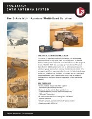
B l a c k r o c k<br />
S I G I N T S y s t e m s I n t e g r a t i o n<br />
PROVIDING THE SIGINT SYSTEM<br />
CAPABILITIES REQUIRED FOR TODAY’S<br />
AIRCRAFT INTEGRATION NEEDS<br />
The Blackrock system is a signals intelligence<br />
(SIGINT) system for integration into intelligence<br />
collection platforms. Blackrock is able to<br />
automatically and manually receive, distribute,<br />
record, and process High Frequency (HF), Very High<br />
Frequency (VHF), and Ultra High Frequency (UHF)<br />
signals. Signals collection and processing activities<br />
provides for robust low-footprint emission direction<br />
finding (DF) capabilities.<br />
Additionally, the Blackrock system can be integrated<br />
with new or existing hardware and software to<br />
provide additional SIGINT and IMINT capabilities.<br />
The system has the ability to integrate with other<br />
subsystems to provide higher fidelity geolocation<br />
capabilities, such as Frequency Difference in Arrival<br />
(FDOA), Time Difference of Arrival (TDOA), and a<br />
DF cueing mechanism for imagery capturing and<br />
recording based on DF results.<br />
SYSTEM CAPABILITIES<br />
• Signals Band Search<br />
• Signals Manual Search<br />
• Signal Seize<br />
• Signal Recording<br />
• Signal Recall<br />
• Signal Panoramic Display<br />
• Audio Distribution<br />
• System Maintenance Integration<br />
AUDIO TASKING & PRIORITY<br />
Twenty-four (24) audio sourced real-time-processing<br />
(RTP) audios are available to operators for analysis<br />
and other signal interaction.<br />
Audio selections automatically assigns (reassigns)<br />
audio channel to the headsets per operator tasking<br />
(last request has priority).<br />
MAINTENANCE FUNCTIONS<br />
Blackrock system maintenance is conducted via the<br />
System Status Panel that indicates specific problem<br />
components while supplying the means to correct<br />
issues by allowing assets to be removed from use,<br />
reset, or functional tested for output.<br />
HARDWARE HIGHLIGHTS<br />
• HF/VHF/UHF Tuners<br />
• Custom Control Processors<br />
• Audio Interfaces<br />
• Video Interfaces<br />
• Network Switches and Severs<br />
• RAID Network Storage<br />
• Navigation Server<br />
4<br />
Mission Integration
B l a c k r o c k<br />
SEARCH AND COLLECTION<br />
Operators are able to interface with the Blackrock collection<br />
system via a robust Search and Collection panel.<br />
• The Search and Collection panel is the primary interface for<br />
operators and maintainers to access the system search and<br />
collection display and controllers.<br />
• All of the functions that encompass search and collection<br />
activity are available to operators and maintainers.<br />
SEARCH AND COPY<br />
The system has one HF and one VHF/UHF tuner for band search<br />
operations. Up to 25 RF spectrum search bands are available<br />
for manual selection or selected from pre-defined parameters.<br />
Additionally, signals can be seized, recorded, or recalled by<br />
operators as needed.<br />
• Operators have the ability to upgrade a selected search hit to a<br />
discrete channel (copy).<br />
• For discrete search (copy) operations, operators have three HF<br />
and three VHF/UHF tuners available.<br />
PAN/SDU INTERFACE<br />
Blackrock contains an interactive panoramic (PAN) display that<br />
allows the user to perform signal inspection and analysis. Users<br />
are able to scan through signals, zoom in and out of signals<br />
based on pre-defined and operator definable pre-sets, and<br />
accomplish signal peak search though a combination of mouse<br />
and keyboard actions.<br />
Also, the system contains an interactive signals display unit<br />
(SDU) display that allows the user to perform additional signal<br />
inspection and analysis. When a receiver is tuned to a signal, the<br />
system displays a pre-defined spectrum width, centered on the<br />
signal’s center frequency. Subsequently, the user is then able to<br />
zoom in and out of signals via the mouse, similar to that of the<br />
PAN display.<br />
Mission Integration 5
G l o b a l S e c u r e I n f o r m a t i o n<br />
M a n a g e m e n t S y s t e m ( G S I M S )<br />
GSIMS is an airborne certified and accredited IP-based executive secure communication system with<br />
a modular, scalable, and redundant design. The end-user experiences the same reliable connectivity,<br />
interoperability and security they would have in an executive office environment. The GSIMS integrates the<br />
Airborne Executive Phone (AEP) using multiple levels of security for digital voice through a single handset and<br />
internet data access. GSIMS integrates existing analog and digital radios with its IP-based architecture.<br />
Key Features<br />
• AEP Provides Secure/Non-Secure Digital <strong>Communications</strong> from a Single Handset<br />
• Assured <strong>Communications</strong> for Emergency and Low Power Operations<br />
• Centralized / Distributed System Control<br />
• Multiple Independent Levels of Security (MILS)<br />
• Secure/Non-Secure Voice, Video Teleconference, and Data Access<br />
• Integrates Existing Analog and Digital Radios with the IP-based Architecture<br />
• Multi-Language<br />
• Wireless Connectivity (Cellular, CDMA, GSM, WiFi)<br />
• Service Oriented and Open Architecture<br />
• Industry Standardized Interfaces<br />
• Bandwidth Monitoring, Prioritization, and Quality of Service Management<br />
• User and Passenger Authentication<br />
• Virtual Controls for Radios and Cryptographic Equipment<br />
• Certified and Accredited to U.S. Government Security Requirements<br />
Applications<br />
• Airborne, Shipboard, Vehicular, and<br />
Office Executive <strong>Communications</strong><br />
System for Senior Leaders<br />
• Commercially Available for<br />
Corporate and VVIP Platforms<br />
6<br />
Mission Integration
R I O<br />
RIO is a signals intelligence software suite used for the intercepting, direction finding, geolocating, monitoring<br />
and recording of communications signals.<br />
FEATURES<br />
• Simultaneously utilizes four tuners<br />
to provide automated, continuous<br />
background signal search, signal<br />
monitoring and recording<br />
• Geolocations of signal transmitters are<br />
determined either through intersecting<br />
Lines of Bearing (LOBs) measured over<br />
time or by Time Difference of Arrival<br />
(TDOA) and Frequency Difference of<br />
Arrival (FDOA) techniques<br />
• LOBs and geolocations are shown on a<br />
fully integrated moving map display<br />
• Rio utilizes commercially available<br />
mapping packages for three-dimensional<br />
display of the area of interest<br />
• Modular and open standard Operating<br />
Systems<br />
• X-<strong>MID</strong>AS applications provide processing<br />
for special signal types<br />
• Hardware enables growth to a SIGINT<br />
system that includes ELINT and Proforma<br />
• Allows user to be remotely located from<br />
the sensor and maintain full control via a<br />
laptop-installed application<br />
• Interactive spectral display allows the<br />
user to select signals based on RF energy<br />
levels and obtain detailed information<br />
such as modulation type, bandwidth, and<br />
center frequency<br />
APPLICATIONS<br />
• Wartime and peackeeping tasks<br />
• Monitoring and geolocation of enemy<br />
communications<br />
• Cueing of imagery sensors for visual<br />
identification<br />
Mission Integration 7
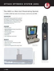
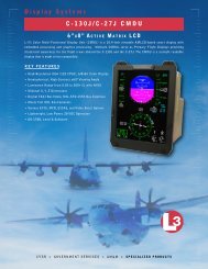
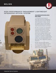
T a c t i c a l V i d e o<br />
Tactical Video Exploitation Suite is an application suite that provides target management, sensor control, and<br />
full motion video recording, exploitation, and distribution in MISB compliant format. Easy to use, DVR - like<br />
interface provides full control of live and recorded video streams. The system is modular and easily integrated.<br />
A Cursor on Target interface utilizes cues from Multi-INT systems to cue EO/IR systems. <strong>MID</strong>’s Tactical Video<br />
Exploitation Suite updates aircraft locations, sensor footprint and viewpoint utilizing KLV encoded meta data<br />
integrated with the Google Earth map and others. Tracks and target information are added to the map<br />
providing complete situational awareness from mission plan to live sensor data. Still images extracted from<br />
the video are rectified and geo-registered into the map. Extracted images can be forwarded to Electronic Light<br />
Table package for further exploitation, or embedded in reports and email. Sensor control for WESCAM MX<br />
series and FLIR Systems Star Safire series.<br />
Key Features<br />
• TRL 8<br />
• KLV 601.4 Transport Stream Encoder<br />
• Tactical Digital Video Recorder and Player<br />
• Tactical Video Exploitation and Reporting<br />
• Tactical Target Manager<br />
• Map Integration<br />
• MISP 5.4, STANAG 4609, STANAG 4545,<br />
NITF 2.1 Compliant<br />
• Available for Windows and Linux<br />
• Scalable Laptop to Data Center<br />
• Sensor Control for WESCAM MX Series<br />
and FLIR Systems Star Safire Series<br />
Applications<br />
• Designed for Air and Ground Use<br />
• Military, Government and Police<br />
8<br />
Mission Integration
E W F l i g h t T e s t R a n g e<br />
L-3 Mission Integration’s Multi-Sensor Flight Test Facility (MSTF) is located on over 100 acres of land adjacent<br />
to <strong>MID</strong>’s main facility in Greenville, Texas. The test range specialize in electronic warfare, reconnaissance,<br />
and communications systems, flight testing and training (SIGINT/ELINT/RWR/ECM); and, red /grey/blue radar<br />
threat simulation from multiple emitters. We offer a low cost solution for commercial or government programs<br />
seesking HF To 40 GHz radiated signal sources for EW Flight Test.<br />
L-3 Mission Integration’s Multi-Sensor Test Range Provides<br />
• Access to over 600 radio frequencies approved<br />
by FCC for testing purposes<br />
• FAA-approved airspace for flight testing<br />
(24x7x365)<br />
• Limited environmental concerns (noise pollution,<br />
endangered species, high population density)<br />
• The ability to land almost any type of aircraft on<br />
its 8,000 foot runway (with 1,000 foot overruns<br />
on each end)<br />
• FAA-certified Air Traffic Control<br />
• FAA-certified Fire/Crash departments<br />
• Department of Defense-certified security<br />
• Technical experience<br />
• Replicates real world electronic environment<br />
including Threat Reproduction/Simulation<br />
• End-to-end electronic system test<br />
• RF signal sources (Broadband, ELINT, High<br />
Power Impulse, Tracking or Mobile)<br />
• Wide array of communication equipment<br />
(Narrowband, Wideband, Agile, Clear, Secure,<br />
LOS, BLOS, SATCOM)<br />
For more information about the L-3 EW Flight Test Range, go to www.l3midwesterntestrange.com.<br />
Mission Integration 9
E l e c t r o m a g n e t i c E f f e c t s<br />
C a pa b i l i t i e s<br />
The Electromagnetic Effects group at L-3 <strong>MID</strong> is fully staffed by Electromagnetic Effects engineers. These<br />
engineers are experienced in E3 and TEMPEST design, and testing of aircraft units and systems. Personnel<br />
certifications include the NARTE EMC Engineer and NSA TEMPEST Engineer designations.<br />
E M I / E M C / T E M P E S T D e s i g n a n d Te s t<br />
• Strict Adherence to Control of EMI<br />
• Safety Issues:<br />
• Interference to Avionics<br />
• Radiation Hazards<br />
• <strong>Communications</strong> Security<br />
• Electromagnetic Pulse (EMP)<br />
D e s i g n S u p p o r t t o H a r d w a r e E n g i n e e r i n g<br />
• Component Selection<br />
• Filtering<br />
• Shielding Effectiveness Analysis<br />
S u p p o r t t o A e r o & S y s t e m s<br />
• EME Analysis<br />
• Identify Potential Incompatibilities Early (so Protection is Designed Into the System)<br />
• High Intensity Radiated Fields (HIRF)<br />
• Lightning Analysis<br />
• Precipitation Static Analysis<br />
• Antenna-to-Antenna Coupling<br />
• Design Support<br />
• Define Shielding and Grounding Schemes<br />
• Define Red/Black Architecture for Secure<br />
Systems<br />
• Define Wire Categories for Interface Cable<br />
Routing<br />
• Define Electrical Bonding Requirements<br />
• Define Lightning Protection<br />
S y s t e m L e v e l Te s t i n g<br />
• EMC Ground Testing<br />
• EMC Flight Testing<br />
• TEMPEST Ground Testing<br />
• TEMPEST Professional Level II Certified<br />
Engineers<br />
• Precipitation Static (P-Static)<br />
• Radiation Hazards<br />
10<br />
Mission Integration
E l e c t r o m a g n e t i c E f f e c t s<br />
C a pa b i l i t i e s<br />
R a d i a t i o n H a z a r d s<br />
• Hazards of Electromagnetic Radiation to Ordinance (HERO)<br />
• Hazards of Electromagnetic Radiation to Fuels (HERF)<br />
• Hazards of Electromagnetic Radiation to Personnel (HERP)<br />
A n t e n n a R a d o m e Tr a n s m i s s i v i t y Te s t i n g<br />
T E M P E S T E v a l u a t i o n s<br />
• Equipment Level Evaluations<br />
• MIL STD-461/ DO-160<br />
• Conducted Emissions<br />
• Radiated Emissions<br />
• Conducted Susceptibility<br />
• Radiated Susceptibility<br />
• Capabilities for Group B EMI Testing<br />
• RTCA DO-160F as defined below:<br />
• Section 16.0 Power Input, Category A equipment<br />
• Section 17.0 Voltage Spike, Category A equipment<br />
• Section 18.0 Audio Frequency Conducted Susceptibility - Power Inputs; Category R equipment<br />
• Section 19.0 Induced Signal Susceptibility (Radiated and Conducted); Category CC equipment<br />
• Section 20.0 Radio Frequency Susceptibility (Radiated and Conducted); Category R equipment (Note 1)<br />
• Section 21.0 Emission of Radio Frequency Energy; Category M equipment<br />
• MIL-STD-461F as defined below:<br />
• CE101 Conducted Emissions, Power Leads,<br />
30 Hz to 10 kHz<br />
• CE102 Conduced Emissions, Power Leads,<br />
10 kHz to 10 MHz<br />
• CS101 Conducted Susceptibility, Power<br />
Leads, 30 Hz to 150 kHz<br />
• CS114 Conducted Susceptibility, Bulk<br />
Cable Injection, 10 kHz to 200 MHz, Curve<br />
3<br />
• CS115 Conducted Susceptibility, Bulk<br />
Notes:<br />
(1) Maximum radiated susceptibility field level from 400<br />
MHz to 8 GHz is 60 V\m<br />
(2) Air Force Aircraft Internal field levels up to a maximum frequency of 8 GHz<br />
Mission Integration 11
500<br />
450<br />
400<br />
350<br />
300<br />
250<br />
200<br />
150<br />
100<br />
50<br />
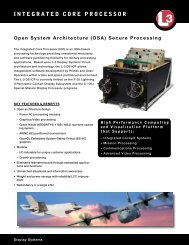
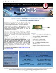
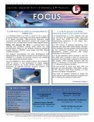
Comparison of Terrain<br />
[ Tgt Emitter On & Intermittent - TDOA/FDOA - Predator North - 446.1 MHz ]<br />
Flat Terrain - ON<br />
Moderate Terrain - ON<br />
Mountainous Terrain - ON<br />
Flat Terrain - Int<br />
Moderate Terrain - Int<br />
Mountainous Terrain - Int<br />
0<br />
0:00 1:00 2:00 3:00 4:00 5:00<br />
Elapsed Time (hh:mm)<br />
1000000<br />
100000<br />
10000<br />
1000<br />
100<br />
10<br />
1<br />
500<br />
450<br />
400<br />
350<br />
300<br />
250<br />
200<br />
150<br />
100<br />
50<br />
Comparison of Terrain<br />
[ Tgt Emitter On & Intermittent - TDOA/FDOA - Predator North - 446.1 MHz ]<br />
Flat Terrain - ON<br />
Moderate Terrain - ON<br />
Mountainous Terrain - ON<br />
Flat Terrain - Int<br />
Moderate Terrain - Int<br />
Mountainous Terrain - Int<br />
0<br />
0:00 1:00 2:00 3:00 4:00 5:00<br />
Elapsed Time (hh:mm)<br />
1000000<br />
100000<br />
10000<br />
1000<br />
100<br />
10<br />
1<br />
cription<br />
LING SIMULATION AND OPERATIONS ANALYSIS CAPABILITIES<br />
cation via the Simulation Software/Matlab interface<br />
• EEP<br />
des a capability M o dto eusers l iwishing n g , to Sobtain i m ugeo‐location<br />
l a t i o n , a n d<br />
rmance based on repeated random trials.<br />
OProposal p e r a tEnhancement<br />
i o n s A n a ly s i s ( M S O A )<br />
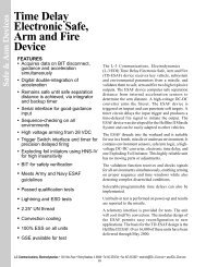
The MSOA team provides products and services for modeling (physical, process, behavioral, or mathematical)<br />
The Antenna complex Pattern information Builder (data) allows into a users an abstraction • Pattern or representation generator for of approximate air and ground main platforms, beam modeling weapons, synthetic The Simulati<br />
to roughly environmental model antenna conditions patterns for Live, in 3D Virtual, by or • Constructive More advanced simulations. Side lobe generator The MSOA simulating team has first experience side lobes<br />
improved ma<br />
in manin-loop<br />
and hardware-in-the-loop simulation software products that support multiple language text to speech<br />
providing details and viewing them in<br />
• Allows user to choose beam widths main lobe and side lobes<br />
application o<br />
azimuth and elevation. The 3D pattern is • Main beam/side lobe placement and amplitude ratio traits<br />
documentati<br />
processing, supporting multiprocessing of real mission data for ELINT, IMINT, and SIGINT driven simulation<br />
t Exploration<br />
saved in an Simulation Software format so<br />
• Provides back lobe amplitude characterization<br />
Additionally,<br />
exercises.<br />
Proposal • User determines Enhancement<br />
dynamic range/peak amplitude of pattern<br />
that the pattern can be attached to emitters<br />
ability to sea<br />
User loads previously built pattern Repeated files for editing Trials<br />
in Simulation Software scenarios.<br />
Communicat<br />
Features N Trial Monte Carlo Analysis only Features files and<br />
essment M o d e l i n g , S i m u l a t i o n a• Evaluate n d Tr <strong>Product</strong> a i nClaims<br />
i n g ( M S & T )<br />
and<br />
mance<br />
• objects Uses Visuc<br />
Coverage Analysis<br />
• What if Analysis 3-D Visualization<br />
location<br />
imization<br />
Enhance data<br />
• Experience and IT infrastructure to support • Visualize unclassified, Concepts collateral, or Summarize TS/SCI distributed MOP simulation Statistics<br />
training<br />
for • passing Helps Ver to<br />
D OPERATIONS exercises Features ANALYSIS CAPABILITIES • Assist in Concept Definition<br />
Customer<br />
• Assist in Risk Reduction Features<br />
• Terrain Masking<br />
A key • Explains compoa<br />
• Use • Sensor of COTS Performance products plus internal M&S applications for effective • Real Time/Recorded operator training Data and data collection for ability than to Grap con<br />
student scorecards and exercise playback\after action reviews<br />
• Multiple Data Formats<br />
appropriate.<br />
mization tenna • Pattern Builder<br />
•<br />
Multiple Course to<br />
Platforms<br />
Fine Granularity Sensor Optimization • • Testing Exercise Support<br />
Support<br />
• Experience integrating COTS, GOTS, and home grown simulation applications to conduct man-in-the-loop or<br />
connection t<br />
• Post Mission Analysis<br />
cription<br />
hardware-in-the-loop M&S training activities Features<br />
over a LAN, a<br />
Features<br />
that are refe<br />
enna Pattern Builder allows a users • Uses Characteristics • of Pattern generator for approximate main beam modeling end database<br />
hly s model antenna patterns in 3D Sensors/Radars/Cameras<br />
by • More advanced Side lobe generator simulating first side lobes<br />
• Uses Terrain Masking<br />
g details and viewing them in • Optimizes for Maximum • Allows user to choose beam widths main lobe and side lobes<br />
and elevation. The 3D pattern is Coverage • Main beam/side lobe placement and amplitude stk.v.7.0 ratio traits<br />
le<br />
• Optimizes to Eliminate<br />
BEGIN Ephemeris<br />
an Simulation Software format Coverage so Gaps<br />
• Provides back lobe amplitude characterization<br />
pattern can be attached to emitters • User determines dynamic range/peak amplitude of pattern<br />
ING SIMULATION AND OPERATIONS<br />
User loads<br />
ANALYSIS<br />
previously built<br />
APPLICATIONS<br />
NumberOfEphemerisPoints 27850<br />
ScenarioEpoch 1 Jan 2007 00:00:00.00000<br />
InterpolationMethod<br />
Lagrange<br />
InterpolationOrder 1<br />
DistanceUnit<br />
Feet<br />
CentralBody<br />
Earth<br />
pattern files for CoordinateSystem editing Fixed<br />
lation Software scenarios.<br />
EphemerisLLATimePos<br />
omparison<br />
ight<br />
s for Accuracy<br />
sent Accurate<br />
n(s)<br />
gement<br />
nications<br />
ager<br />
er<br />
Antenna Pattern Builder<br />
Description<br />
MODELING SIMULATION AND OPERATIONS ANALYSIS CAP<br />
Random Parameter Interface<br />
Description<br />
Features<br />
Features<br />
Features<br />
• Terrain Masking<br />
• Sensor Performance<br />
• Multiple Platforms<br />
• Course to Fine Granularity<br />
Measures of Performance (MOPs)<br />
• Time to Actionable Estimate<br />
• Position Error<br />
1 32.04349274 -93.91416643 479.573<br />
Network Modeling<br />
Description<br />
The Random Parameter Interface allows for simulation of<br />
Integrate QualNet (comms protocol simulator) with ISR<br />
ser to model parameter characteristics under probabilistic assumptions. • Capability to assign PDF to essentially<br />
ational Traffic in Arms Regulations (ITAR), and my not be exported to a Foreign Person, Mission Simulator scenarios. Improved fidelity of multinode/networked<br />
entity simulations with high fidelity<br />
This capability leverages Simulation Software and Matlab to<br />
any<br />
either<br />
object<br />
in<br />
characteristic<br />
the U.S. or abroad, without a license or exemption from the U.S. Department of State”<br />
Positioning<br />
Coverage Analysis<br />
accomplish simulations.<br />
• Easily Simulation Software integration<br />
d simulations<br />
communication protocol simulations.<br />
Applications<br />
• Key component to Monte Carlo analysis<br />
• Random Conversation Intervals<br />
• Lognormal PDF<br />
• Random Target Locations<br />
• Uniform Distribution within select area<br />
Application<br />
Concep<br />
15 32 04349274 93 91416643 479 573<br />
• Real‐time scenario execution<br />
• Capability to select a single sou<br />
and then multiple 3-D destination Vis f<br />
Simulation<br />
Software<br />
2. Inno<br />
(Euc<br />
Algo<br />
Drew the<br />
Applications<br />
Difference of Arrival (TDOA), Frequency Difference off Repeated Trials<br />
Statistica<br />
al (FDOA), and Features Direction of Arrival (DOA) measurements N Features Trial • Monte Monte Carlo Carlo Analysis – Repeated Trails did not l<br />
rocessed using<br />
• Evaluate<br />
a two<br />
<strong>Product</strong><br />
state<br />
Claims<br />
Extended Kalman Filter. The • Uses Visualization • Selection to of Platform Capabilities<br />
• What if Analysis<br />
better pr<br />
Enhance • Concept Evaluation Design of Algorithm Performance in<br />
estimates the • Visualize latitude Concepts and longitude of the emitter<br />
• Helps Verify Specific Details of Operational Environments associati<br />
• Assist in Concept Definition<br />
ng the measurements.<br />
Customer Summarize Requirements MOP Statistics<br />
• Assist in Risk Reduction<br />
L-3 <strong>MID</strong> MSOA team has the experience to solve today’s complex • Explains Modeling, an Idea Better Simulation, and Analysis challenges<br />
than Graphs/Charts Alone<br />
of conducting distributed joint distributed simulation One exercises, Trial performing effective mission rehearsal,<br />
operations analysis, creating and verifying models, recommending M&S tools and infrastructure products that<br />
satisfies dynamic specifications, regulations, and requirements.<br />
Modeling<br />
Semi-Major Axis (meters)<br />
Semi-Major Axis (meters)<br />
Concept Enhancement<br />
0 32.04349274 -93.91416643 479.573<br />
2 32.04349274 -93.91416643 479.573<br />
3 32.04349274 -93.91416643 479.573<br />
4 32.04349274 -93.91416643 479.573<br />
5 32.04349274 -93.91416643 479.573<br />
6 32.04349274 -93.91416643 479.573<br />
7 32.04349274 -93.91416643 479.573<br />
8 32.04349274 -93.91416643 479.573<br />
9 32.04349274 -93.91416643 479.573<br />
10 32.04349274 -93.91416643 479.573<br />
-93.91416643 479.573<br />
-93.91416643 479.573<br />
Features<br />
-93.91416643 479.573<br />
11 32.04349274<br />
12 32.04349274<br />
13 32.04349274<br />
14 32.04349274 -93.91416643 479.573<br />
Sim<br />
Descrip<br />
“This technical data is controlled under the International Traffic in Arms Regulat<br />
Operations Analysis<br />
Features<br />
• Complex System Interactions<br />
• Discrete and Continuous<br />
Random Variables<br />
• Event Based Behavior<br />
• Detailed Sensor Performance<br />
• Monte Carlo Analysis<br />
Features<br />
• Real Time<br />
• Multiple<br />
• Exercise S<br />
• Testing S<br />
• Post Miss<br />
Post‐Run<br />
Manager<br />
Post‐Run<br />
Plugin<br />
“This technical data is controlled under the International Traffic in<br />
ISR Vis Tool<br />
Features<br />
OPs)<br />
Description<br />
Features<br />
Description<br />
• Use several different modelin<br />
• Supports HiFiSim suite with visualization<br />
The 3‐D Model Design is the ability to model, remodel, or<br />
• Import/Export scenarios between<br />
from existing models<br />
• Facilitates SME review, quality checking of inputs<br />
12 Mission Integration<br />
Simulation Software & HiFiSim<br />
convert 3‐D models that a customer wants for the simulation. • Add or modify an existing mo<br />
• Interface (limited) from HiFiSim suite to Simulation • Add SME metadata to scenario<br />
• Through Sketchup, a vast, free<br />
“This technical data Software is controlled applications under the International Traffic in Arms Regulations (ITAR), and my not be exported to a Foreign Person, either in the U.S. or abroad, without a license<br />
• Enhanced visualizations (e.g. Mil‐Stdmodels<br />
available for use<br />
Semi-Major Axis (meters)<br />
3-D Model Design<br />
Semi-Major Axis (meters)
M o d e l i n g , S i m u l a t i o n , a n d<br />
O p e r a t i o n s A n a ly s i s ( M S O A )<br />
M o d e l i n g a n d S i m u l a t i o n – O p e r a t i o n s A n a l y s i s ( M & S - O A )<br />
• Proven analytical methodology for conducting research studies and acquisition decision to support a<br />
Program’s specification and requirements<br />
• M&S scientific and technical analysis functions tailored to support the M&S community<br />
• Research and development activities using L-3 <strong>MID</strong> proven process methodologies combined with<br />
industry best practices to enhance the ability to access, acquire, collect, analyze, synthesize,<br />
generate and report M&S related technical information<br />
• Analysis of M&S model(s) performance measures oversight<br />
• Research and development of Measures of Effectiveness (MOE) for determining the impact of<br />
simulations on the training, analysis and acquisition processes<br />
Modeling and Simulation – Management Support (M&S-MS)<br />
• Onsite and/or distributed training exercises, mission rehearsals, analytical studies, etc., or<br />
identification of viable options for simulation support<br />
• Program reviews, strategic planning, and exercise management<br />
• Operations coordination and monitoring of M&S training, exercises, and operations<br />
• M&S program reviews, and strategic planning<br />
• Configuration, product line, release, and document management of M&S software<br />
• Requirements, simulation event incidents, defects, and corrective action reports management for M&S<br />
software, products, artifacts<br />
• <strong>Communications</strong> and distribution mechanisms for M&S artifacts and related materials<br />
• Research, develop, implement, and evaluate collaborative simulation modeling and analysis tools<br />
Mission Integration 13
M o d e l i n g , S i m u l a t i o n , a n d<br />
O p e r a t i o n s A n a ly s i s ( M S O A )<br />
S t a n d a r d s , A s s e s s m e n t , Ve r i f i c a t i o n , a n d Va l i d a t i o n<br />
( M & S - S AV V )<br />
• Onsite and/or distributed training exercises, mission rehearsals, analytical studies, etc., or identification of<br />
viable options for simulation support<br />
• Performance measures verification, and validation of simulation model(s)<br />
• Techniques, tactics, and procedures verification, and validation for mission specific simulation exercises and<br />
rehearsals<br />
• Compliancy oversight, guidance, and support for DoD certification of High Level Architecture (HLA) and other<br />
M&S standards<br />
• Assessments mapping of simulation models’ vulnerability and survivability<br />
• Research, develop, and execute applied standard verification and validation (V&V) processes to selected models<br />
and simulations<br />
• Guidelines, oversight, and procedures to analyze and compare V&V results with objective model acceptance<br />
criteria in support of M&S accreditation<br />
• Analysis of compared V&V results with objective model acceptance criteria in support of M&S accreditation<br />
• Improve models, products, and artifacts by analyzing feedback from actual combat experience and applying<br />
appropriate updates into the model and comparing the results with actual combat results and investigating any<br />
ambiguities that result to check the model’s validity<br />
14<br />
Mission Integration
M o d e l i n g , S i m u l a t i o n , a n d<br />
O p e r a t i o n s A n a ly s i s ( M S O A )<br />
S i m u l a t i o n I n t e g r a t e d L a b ( S I L )<br />
• Conduct software and systems integration testing, acceptance testing, and V&V testing<br />
• Conduct sensitive compartmented<br />
information testing, simulation training,<br />
and exercises<br />
• Accessible and secure facility to conduct<br />
M&S events Program reviews, strategic<br />
planning, and<br />
exercise management<br />
Mission Integration 15
Pa i n t Fa c i l i t i e s<br />
L-3 Mission Integration’s modern aircraft paint facilities include two paint hangars. The primary facility is<br />
capable of painting the surface area of a Boeing 747-400. It is equipped with two platform lifts that can move<br />
the length and width of the hangar to reduce cycle time. An electrostatic paint system reduces overspray<br />
and increases painting efficiency. A foam-water deluge system, four foam-water nozzles, and ultraviolet and<br />
infrared sensors provide excellent fire protection during the painting process. The second facility is capable of<br />
de-painting a Boeing 757. This advanced, temperature-controlled facility offers five automated ventilation and<br />
exhaust methods to facilitate different washing, de-painting or painting procedures. A high-capacity filtration<br />
system allows <strong>MID</strong> to perform painting/de-painting services in a nearly particle-free environment. This facility<br />
also houses numerous water and solution tanks, and an aqueous film forming foam (AFFF) emergency fire<br />
system, with over a million gallons available for fire safety purposes. Furthermore, there are workstands and<br />
component-holding fixtures that improve cycle time in de-painting and painting operations.<br />
Whether your needs are basic or fastidious, our personnel have the experience you demand. <strong>MID</strong> offers premier<br />
services in aircraft de-painting, exterior painting and interior. Our facilities are capable of handling virtually any<br />
aircraft finishing for aircraft ranging from VIP aircraft to aircraft for military service.<br />
16<br />
Mission Integration
Pa i n t Fa c i l i t i e s<br />
Each facility is equipped with environmental controls, modern equipment, and fire protection systems. Our<br />
processes are ISO 9001 certified and compliant with all federal and state safety regulations. In addition, our<br />
facilities can fabricate CAD driven stencil design.<br />
<strong>MID</strong> has extensive experience in applying finishes for many different aircraft, including: Boeing 707, 737, 747,<br />
and 757, P-3, C-5, C-18, C-20, KC-10, C-22, C-47, C-130, C-135, A310, A340, Gulfstream III, IV, E-6B, E-8, MD-<br />
11, and VC-137.<br />
Mission Integration 17
18<br />
Mission Integration
Mission Integration 19
L-3 <strong>Communications</strong><br />
Mission Integration<br />
10001 Jack Finney Blvd.<br />
Greenville Texas 75402<br />
P.O. Box 6056<br />
www.L-3Com.com/IS<br />
(866) 532-4477<br />
BD10-315<br />
“This data sheet/brochure has been released into the public domain in accordance with International Traffic in Arms Regulations (ITAR) 22 CFR 120.11(6).”