Roller Chain Couplings - U.S. Tsubaki, Inc.
Roller Chain Couplings - U.S. Tsubaki, Inc.
Roller Chain Couplings - U.S. Tsubaki, Inc.

Create successful ePaper yourself
Turn your PDF publications into a flip-book with our unique Google optimized e-Paper software.
U.S. <strong>Tsubaki</strong>, <strong>Inc</strong>.<br />
Power Transmission Components Division<br />
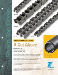
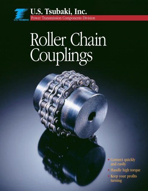
<strong>Roller</strong> <strong>Chain</strong><br />
<strong>Couplings</strong><br />
• Connect quickly<br />
and easily<br />
• Handle high torque<br />
• Keep your profits<br />
turning
<strong>Roller</strong> <strong>Chain</strong> <strong>Couplings</strong><br />
The Quality Connection<br />
<strong>Roller</strong> <strong>Chain</strong> <strong>Couplings</strong> from U.S. <strong>Tsubaki</strong> are your connection to better<br />
profits and productivity. We’ve combined the best in the business —<br />
high-quality <strong>Roller</strong> <strong>Chain</strong> with a pair of specially cut, hardened-tooth<br />
Sprockets — to create a powerful, flexible coupling that keeps your<br />
operation running at peak performance.<br />
For clean areas and light loads,<br />
choose our Nylon <strong>Chain</strong> <strong>Couplings</strong>. Assembled<br />
couplings are also available upon request.<br />
Sprocket<br />
(induction hardened teeth)<br />
Double Strand<br />
<strong>Roller</strong> <strong>Chain</strong><br />
(coupling chain)<br />
Make the Connection<br />
Farming... mining... metal manufacturing...and more. When you need to<br />
connect two shafts, <strong>Roller</strong> <strong>Chain</strong> <strong>Couplings</strong> from U.S. <strong>Tsubaki</strong> are the right choice.<br />
You can’t make a better match!<br />
Spring Clip<br />
Connecting Pin<br />
• Simple to Install<br />
Save valuable production time by getting your lines up and running fast. Simple construction<br />
makes our units easy to install, remove, and replace. Our unique, single-pin connection<br />
of the chain keeps downtime — and hassles — to a minimum. One clip is all it takes!<br />
• Compact and Powerful<br />
Remarkably efficient construction transmits torque easily by apportioning it over the entire<br />
strand of roller chain and all the sprocket teeth. You get the power you need to drive your<br />
business at an economical unit price.<br />
• Flexible for Easy Alignment<br />
Clearances within the chain itself and between the chain and the sprocket teeth make our<br />
<strong>Roller</strong> <strong>Chain</strong> <strong>Couplings</strong> flexible and responsive. They align quickly and accurately and protect<br />
against overheating and abrasion caused by expansion or contraction of the shaft. You<br />
save time and money on adjustments and repairs.<br />
• Built to Last<br />
Get the only flexible coupling on the market built to the quality standards of U.S. <strong>Tsubaki</strong>.<br />
Special double-strand roller chain with single-pin connector. Precision hardened sprockets<br />
with our standard dual set screw locking arrangment. The durability you need to handle<br />
high speed and torque, keeping maintenance and replacement costs low.<br />
❶
Coupling Covers Add Safety<br />
and Efficiency<br />
Coupling Covers improve the safety, cleanliness, and overall<br />
performance of your system. Safe and smart, they protect the unit<br />
from outside elements and provide better workplace operation.<br />
• Split-type construction provides easy installation and inspection.<br />
• Continuous lubrication keeps lines running smoothly with<br />
minimum maintenance, extending service life.<br />
• Smooth-surface design covers entire unit with no projecting bolts,<br />
providing a neat appearance and safe operation.<br />
Reduce Your Hassles with<br />
a Single, Reliable Source<br />
Partner with U.S. <strong>Tsubaki</strong> for savings and convenience. You benefit from the power of one:<br />
• One call to get the highest quality power transmission products available<br />
• One order to track<br />
• One delivery to handle<br />
• One invoice to process<br />
Time is money. Reduce your processing time and increase your profits with a single call to U.S. <strong>Tsubaki</strong>.<br />
The Key to Quick Connections<br />
Keep downtime to a minimum with our unique single-pin<br />
connection — available only from U.S. <strong>Tsubaki</strong>. A single pin holds<br />
the chain in place for easy installation. You spend less time setting<br />
up your equipment and can quickly get production rolling.<br />
❷
Selection Guidelines<br />
Required Information<br />
1. Number of hours of daily operation<br />
2. Classification of load and prime mover<br />
3. Horsepower or required torque to be transmitted and shaft speed in revolutions/minute<br />
4. Diameter of both shafts<br />
Method for Selection<br />
1. Based on the operating conditions, determine the Service<br />
Factor, using Table 1.<br />
2. Obtain the design horsepower by multiplying the<br />
horsepower to be transmitted by the Service Factor.<br />
3. With the required rpm, choose the coupling that satisfies the<br />
horsepower from the Horsepower Rating, shown in Table 2.<br />
4. When the required shaft diameter exceeds the maximum<br />
bore diameter of the coupling you have chosen, use a<br />
coupling that is one size larger.<br />
5. In the low-speed range, the shearing pressure might be too<br />
great when using a standard key. In this case, calculate the<br />
key shearing pressure to determine if it is necessary to use<br />
a special key or spline bore.<br />
6. Note the lubrication system required and select the coupling<br />
cover as necessary. In all applications, use of a coupling<br />
cover will provide quieter running, longer life, and safer<br />
operation.<br />
Table 1. Service Factor<br />
Source of Power<br />
Electric Reciprocating Reciprocating<br />
motors or engines engines<br />
steam 4 or more less than<br />
Load Classification turbines cylinders 4 cylinders<br />
Uniform load, little shock, low<br />
starting torque, no reversing 1.0 1.5 2.0<br />
Moderate fluctuation of load,<br />
moderate shock, no reversing<br />
(for most common applications) 1.5 2.0 2.5<br />
Large fluctuations of load, heavy<br />
shock, reversal under load, full<br />
load starting 2.0 2.5 3.0<br />
Note: Additional service factor for <strong>Roller</strong> <strong>Chain</strong><br />
Coupling by operating hours (at 50 r/min and more)<br />
8 hours to 16 hours/day - 0.5<br />
16 hours or more/day - 1.0<br />
Table 2. HP Rating Table<br />
Max Allowable<br />
Cplg<br />
Speed of rotation (rpm)<br />
Transmissible<br />
No. Torque at Below 1 5 10 25 50 100 200 300 400 500 600 800 1000 1200 1500 1800 2000 2500 3000 3600 4000 4800<br />
50 rpm (in lbs.)<br />
4012 1921 0.03 .015 0.30 0.78 1.54 2.32 3.53 4.64 5.57 6.65 7.60 9.40 11.44 12.98 15.56 18.37 19.85 24.00 27.76 32.32 35.32 41.30<br />
4016 3416 0.05 0.28 0.55 1.38 2.76 4.14 6.29 8.27 9.94 11.87 13.54 6.76 20.52 23.20 28.16 32.72 35.27 42.78 49.62 57.66 62.89 73.62<br />
5016 6505 0.11 0.52 1.05 2.61 5.24 7.86 11.96 15.69 18.91 22.52 25.75 31.92 38.76 44.12 53.51 62.22 67.05 81.27 94.41 109<br />
5018 8240 0.13 0.67 1.33 3.33 6.64 9.96 15.15 19.98 23.87 28.56 32.72 40.36 49.08 55.79 67.72 78.85 85.02 103 120<br />
6018 15489 0.24 1.25 2.51 6.26 12.51 18.77 28.56 37.55 45.06 53.77 61.55 76.17 92.66 105 128 149 161 194<br />
6020 17868 0.28 1.43 2.88 7.21 14.34 21.55 23.72 43.17 51.85 61.90 70.84 87.59 106.58 121 147 171 185 223<br />
8018 34341 0.55 2.78 5.55 13.81 27.76 41.57 63.30 83.28 99.91 119 135 169 205 233 283 330 355<br />
8020 41027 0.66 3.30 6.61 16.49 33.05 49.55 75.17 99.22 118.54 141.3 162 201 244 278 337 393 423<br />
10020 77710 1.25 6.25 12.51 31.25 62.49 93.87 142 188 225 268 307 380 463 526 638 743<br />
Lubrication System 1 2 3<br />
❸
Standard RC <strong>Couplings</strong> Specification Table<br />
Approx Single Spkt Cplg <strong>Chain</strong> Assembled<br />
Cplg No. Std Finished Bores Bore Dia. A B C L Cplg. Wt.(lbs) Wt.(lbs) Cplg Inertia<br />
<strong>Inc</strong>l. Std KW &2 SS Min. Max. OD. Approx Approx (in lb sec^2)<br />
4012 ¹⁄₂, ⁵⁄₈, ³⁄₄ ¹⁄₂ ⁷⁄₈ 1¹³⁄₃₂ 1¹⁄₈ ⁹⁄₃₂ 2¹⁷⁄₃₂ 2¹³⁄₃₂ 0.5 0.4 0.20 x 10 -2<br />
4016 ⁵⁄₈, ³⁄₄, ⁷⁄₈, ¹⁵⁄₁₆ ¹⁄₂ 1⁵⁄₁₆ 1³¹⁄₃₂ 1¹⁄₈ ⁹⁄₃₂ 2¹⁷⁄₃₂ 3¹⁄₃₂ 1 0.6 0.60 x 10 -2<br />
1, 1¹⁄₈, 1³⁄₁₆*, 1¹⁄₄*<br />
5016 ³⁄₄, ⁷⁄₈, 1, 1¹⁄₈, 1 ⁵⁄₈ 1¹¹⁄₁₆ 2¹⁄₂ 1⁷⁄₁₆ ³⁄₈ 3¹⁄₄ 3²⁵⁄₃₂ 2.2 1.2 1.89 x 10 -2<br />
1¹⁄₄, 1³⁄₈, 1⁷⁄₁₆, 1¹⁄₂, 1⁵⁄₈*<br />
5018 ³⁄₄, ⁷⁄₈, 1, 1¹⁄₈, 1 ⁵⁄₈ 2 2³¹⁄₃₂ 1¹¹⁄₁₆ ³⁄₈ 3³⁄₄ 4³⁄₁₆ 3.5 1.4 3.39 x 10 -2<br />
1¹⁄₄, 1³⁄₈, 1⁷⁄₁₆, 1¹⁄₂, 1⁵⁄₈,<br />
1³⁄₄, 1⁷⁄₈*, 1¹⁵⁄₁₆*<br />
6018 1, 1¹⁄₈, 1³⁄₁₆, 1¹⁄₄ 1 2⁷⁄₁₆ 3¹⁄₂ 1⁷⁄₈ ⁷⁄₁₆ 4³⁄₁₆ 5 5 2.4 8.09 x 10 -2<br />
1.⁷⁄₁₆, 1¹⁄₂, 1⁵⁄₈, 1³⁄₄, 1⁷⁄₈,<br />
1¹⁵⁄₁₆, 2, 2¹⁄₈, 2³⁄₁₆, 2¹⁄₄,<br />
2³⁄₈*, 2⁷⁄₁₆*<br />
6020 1¹⁄₈, 1¹⁄₄, 1¹⁄₂, 1³⁄₄ 1 2³⁄₄ 3⁷⁄₈ 2 ⁷⁄₁₆ 4⁷⁄₁₆ 5¹⁄₂ 6.5 2.6 12.4 x 10 -2<br />
2¹⁄₈, 2³⁄₈*, 2⁷⁄₁₆*, 2⁵⁄₈*<br />
8018 1¹⁄₈, 1³⁄₄, 1¹⁵⁄₁₆, 2 1¹⁄₈ 3¹⁄₈ 4⁹⁄₁₆ 2³⁄₈ ⁹⁄₁₆ 5²¹⁄₆₄ 6⁵⁄₈ 11 5.5 31.9 x 10 -2<br />
2³⁄₈, 2⁷⁄₁₆, 2⁵⁄₈, 2⁷⁄₈*,<br />
2¹⁵⁄₁₆*<br />
8020 1¹⁄₂, 2³⁄₁₆, 2⁷⁄₁₆, 2 1¹⁄₈ 3⁹⁄₁₆ 5³⁄₈ 2⁵⁄₈ ⁹⁄₁₆ 5¹⁄₂ 7⁹⁄₃₂ 16.3 6.1 53.8 x 10 -2<br />
2¹⁵⁄₁₆, 3¹⁄₈, 3³⁄₈*, 3⁷⁄₁₆*<br />
10020 2, 3³⁄₈, 3⁷⁄₁₆, 3¹⁵⁄₁₆ 1¹⁄₂ 4⁵⁄₈ 6²³⁄₃₂ 3¹⁄₈ ²³⁄₃₂ 6³¹⁄₃₂ 9¹⁄₈ 31.8 10.8 158 x 10 -2<br />
Notes: The dimensions marked with an asterisk indicates set screws at 90 deg. from keyway.<br />
Covers<br />
Covers allow excellent lubrication, and their use is suggested on all applications to increase both product life and safety.<br />
Cover For Wt. Cplg. Cover Inertia<br />
Part No. Sizes D W Lbs. (in lb. sec `2)<br />
40 Cover<br />
50 Cover<br />
60 Cover<br />
80 Cover<br />
10020 Cover<br />
4012 - 4016<br />
5016 - 5018<br />
6018 - 6020<br />
8018 - 8020<br />
10020<br />
4<br />
5¹⁄₈<br />
6³⁄₈<br />
8³⁄₁₆<br />
10¹⁄₈<br />
2<br />
2³⁄₈<br />
2¹⁵⁄₁₆<br />
4<br />
5¹⁄₄<br />
.85<br />
1.45<br />
2.55<br />
5.05<br />
12.55<br />
0.69 x 10 -2<br />
2.00 x 10 -2<br />
5.40 x 10 -2<br />
18.9 x 10 -2<br />
55.8 x 10 -2<br />
Aluminum covers are supplied with seals to cover the listed sizes.<br />
Covers have a rounded exterior in order to offer protection to screw heads.<br />
❹
QD ® Coupling<br />
TAPER-LOCK ® Coupling<br />
• QD ® <strong>Couplings</strong><br />
Coupling Max. Torque Max. Coupling Wt.<br />
Number Bushing (in lbs. unit) Bore* A B C D L O.D. K** Lbs.***<br />
4016JA JA 1000 1 2 7<br />
⁄8<br />
9<br />
⁄32 1 5 ⁄16 2 29 ⁄32 3 1 ⁄32 1 1 ⁄4 .90<br />
5018SH SH 3500 1 3 ⁄8 2 31 ⁄32 1 3<br />
⁄8 1 1 ⁄2 3 3 ⁄8 4 3 ⁄16 1 3 ⁄4 1.30<br />
6020SK SK 7000 2 1 ⁄8 3 7 ⁄8 1 1 ⁄4<br />
7<br />
⁄16 1 7 ⁄8 4 3 ⁄16 5 1 ⁄2 2 1 ⁄4 2.50<br />
8018SF SF 11,000 2 5 ⁄16 4 9 ⁄16 1 3 ⁄4<br />
37<br />
⁄64 2 3 ⁄8 5 21 ⁄64 6 21 ⁄32 2 1 ⁄4 5.30<br />
*Maximum bore indicated is the maximum bore suggested with standard keyway.<br />
**K dimension reflects the minimum clearance to remove the coupling half by using the screws as jack screws.<br />
***Approximate weight of coupling half with bushing.<br />
• TAPER-LOCK ® <strong>Couplings</strong><br />
Type “TLH” Type “TLF” Max. Bushing Data<br />
Coupling Coupling Torque Bushing Max. Min. Coupling Wt.<br />
Number Number (in lbs.unit) Used Bore Bore A B C J* K** L O.D. Lbs.***<br />
4016TLH 4016TLF 1300 1108 1 1 ⁄8<br />
1<br />
⁄2 1 31 ⁄32<br />
7<br />
⁄8<br />
9<br />
⁄32<br />
5<br />
⁄8<br />
3<br />
⁄4 2 1 ⁄32 3 1 ⁄32 .90<br />
5018TLH 5018TLF 4300 1610 1 5 ⁄8<br />
1<br />
⁄2 2 31 ⁄32 1 3<br />
⁄8<br />
13<br />
⁄16 1 1 ⁄16 2 3 ⁄8 4 3 ⁄16 1.10<br />
6020TLH 6020TLF 7150 2012 2 1<br />
⁄2 3 7 ⁄8 1 1 ⁄4<br />
7<br />
⁄16<br />
15<br />
⁄16 1 3 ⁄8 2 15 ⁄16 5 1 ⁄2 2.70<br />
8020TLH 8020TLF 24,000 3020 3 1 5 ⁄16 5 3 ⁄8 2<br />
37<br />
⁄64 1 3 ⁄16 2 1 ⁄16 4 37 ⁄64 7 19 ⁄64 6.10<br />
10020TLH 10020TLF 44,800 3535 3 1 ⁄2 1 3 ⁄16 6 23 ⁄32 3 1 ⁄2<br />
23<br />
⁄32 2 2 5 ⁄8 7 23 ⁄32 9 1 ⁄8 19.00<br />
NOTE:<br />
For H type TAPER-LOCK bushing installs from the hub side of the flange.<br />
For F type TAPER-LOCK bushing installs from the face side.<br />
*Space required to tighten bushing with shortened hex key. Space is also required to loosen screws to permit the removal of the hub by the puller.<br />
**Space required to loosen bushing with shortened hex key using screws as jack screws. No puller is required.<br />
***Approximate weight of coupling half with bushing.<br />
QD ® is a registered trademark of and is used under license from Emerson Electric Company.<br />
TAPER-LOCK ® is a registered trademark of Reliance Electric Company.<br />
Lubrication<br />
Choose one of the following lubrication systems when using <strong>Roller</strong> <strong>Chain</strong> <strong>Couplings</strong>. The choice depends upon<br />
the operating speed. (Refer to the Horsepower Ratings, Table 2, pg.3.) Use NLGI grade 1 or 2 grease.<br />
Lubrication System 1<br />
Apply grease regularly<br />
once per month.<br />
Lubrication System 2<br />
Apply grease regularly once<br />
a week, or install a coupling<br />
cover filled with grease.<br />
Lubrication System 3<br />
Install a coupling cover filled<br />
with grease. Change the<br />
grease according to Table 4.<br />
The amount of grease to apply is shown in Table 3. If these amounts are followed, there will be a slight amount<br />
of leakage at the beginning of the operation, but this will soon stop.<br />
For System 3, it is especially important to use high-grade grease. Because of centrifugal force, there is a tendency<br />
for the grease to stick to the inner surface of the cover, resulting in inadequate lubrication.<br />
Table 3. Amount of Grease to Apply<br />
Coupling Cover Size Amount (lb)<br />
40 Cover .16<br />
50 Cover .32<br />
60 Cover .71<br />
80 Cover 1.41<br />
100 Cover 3.00<br />
Table 4. Grease Change Interval for use with Coupling Cover<br />
Interval after<br />
Operating Conditions First change first change<br />
More than 1/2 max. speed 1,000 hours 2,000 hours<br />
Less than 1/2 max. speed 2,000 hours 4,000 hours<br />
❺
Installation<br />
1. Place the oil seals for the cover on the sprocket<br />
halves.<br />
2. Bring the sprocket faces close together and correct<br />
the angular and offset misalignment.<br />
3. Measure the distance<br />
“C” between the sprocket<br />
faces and firmly fasten<br />
the set bolt (refer to<br />
Specifications table, pg.4).<br />
4. Lubricate the chain with<br />
grease, then wrap the<br />
chain around both<br />
sprockets and fix with<br />
the connecting pin.<br />
5. Fill the required quantity of grease into both sides<br />
of case and fasten them firmly. Do not forget to<br />
use gaskets.<br />
Adjust the angular<br />
misalignment (alpha<br />
symbol) so that the width<br />
of the tooth surface T is<br />
the same around the<br />
circumference of the<br />
sprockets. The allowable<br />
angular misalignment<br />
is 1˚.<br />
Place a straight edge at the<br />
bottom of corresponding<br />
teeth of the two sprockets<br />
and adjust so that the<br />
offset misalignment is<br />
minimized. The allowable<br />
offset misalignment<br />
is 2% of the chain pitch.<br />
Notes: 1. During high-speed operations or conditions<br />
of large vibration, please use locking cement<br />
when fastening the bolts.<br />
2. Install a cover when there is a risk of<br />
chain breakage.<br />
3. Ambient temperature range is 14˚ to 140˚F. If<br />
you will use the coupling outside this<br />
temperature range, please consult with<br />
U.S. <strong>Tsubaki</strong>.<br />
When the sprocket speed is 1/3 or more of the<br />
maximum speed (i.e., it lies on the right side of the<br />
dark line in the Horsepower Rating table, pg.3), the<br />
allowable angular and offset misalignments are 0.5˚<br />
and 1% of the chain pitch.<br />
❻
U.S. <strong>Tsubaki</strong>—<br />
<strong>Roller</strong> <strong>Chain</strong> Coupling<br />
• Connect quickly and easily<br />
• Handle high torque<br />
• Keep your profits turning<br />
U.S. <strong>Tsubaki</strong>, <strong>Inc</strong>.<br />
Headquarters<br />
301 E. Marquardt Drive<br />
Wheeling, IL 60090<br />
Tel: (800) 323-7790<br />
Tel: (847) 459-9500<br />
Fax: (847) 459-9515<br />
Web Site: www.ustsubaki.com<br />
Service Centers<br />
Manufacturing Facilities<br />
Atlanta, GA<br />
U.S. <strong>Tsubaki</strong>, <strong>Inc</strong>.<br />
675 Wesleyan Drive, S.W.<br />
Atlanta, GA 30336<br />
Tel: (800) 443-8212<br />
Tel: (404) 349-7973<br />
Fax: (404) 349-7975<br />
Charlotte, NC<br />
B.C. & H. Company<br />
11010 Monroe Road<br />
Matthews, NC 28105<br />
Tel: (704) 847-9131<br />
Fax: (704) 847-3651<br />
Chicago, IL<br />
U.S. <strong>Tsubaki</strong>, <strong>Inc</strong>.<br />
301 E. Marquardt Drive<br />
Wheeling, IL 60090<br />
Tel: (800) 323-7790<br />
Tel: (847) 459-9500<br />
Fax: (847) 459-9515<br />
Dallas, TX<br />
Robco, <strong>Inc</strong>.<br />
1523 Crescent Drive<br />
Carrollton, TX 75006<br />
Tel: (972) 242-3300<br />
Fax: (972) 245-2328<br />
Los Angeles, CA<br />
U.S. <strong>Tsubaki</strong>, <strong>Inc</strong>.<br />
18031 Cortney Court<br />
City of Industry, CA 91748<br />
Tel: (800) 352-4315<br />
Tel: (626) 913-1344<br />
Fax: (626) 913-5042<br />
Philadelphia, PA<br />
U.S. <strong>Tsubaki</strong>, <strong>Inc</strong>.<br />
2321 N. Penn Road<br />
Hatfield, PA 19440<br />
Tel: (800) 258-3847<br />
Tel: (215) 997-9170<br />
Fax: (215) 997-9179<br />
Portland, OR<br />
U.S. <strong>Tsubaki</strong>, <strong>Inc</strong>.<br />
14157 N.E. Airport Way<br />
Portland, OR 97230<br />
Tel: (800) 352-4315<br />
Fax: (626) 913-5042<br />
Bennington, VT<br />
Sprocket Division<br />
222 Bowen Road<br />
Bennington, VT 05201<br />
Tel: (800) 451-4441<br />
Tel: (802) 447-7561<br />
Fax: (802) 447-0755<br />
Holyoke, MA<br />
<strong>Roller</strong> <strong>Chain</strong> Division<br />
821 Main Street<br />
Holyoke, MA 01040<br />
Tel: (800) 628-9037<br />
Tel: (413) 536-1576<br />
Fax: (413) 534-8239<br />
Sandusky, OH<br />
Engineering <strong>Chain</strong><br />
Division<br />
1010 Edgewater Drive<br />
Sandusky, OH 44870<br />
Tel: (800) 537-6140<br />
Tel: (419) 626-4560<br />
Fax: (419) 626-5194<br />
Mississauga, ON<br />
<strong>Tsubaki</strong> of Canada<br />
Limited.<br />
1630 Drew Road<br />
Mississauga, ON<br />
Canada L5S 1J6<br />
Tel: (800) 263-7088<br />
Tel: (905) 676-0400<br />
Fax: (905) 676-0904<br />
Distributed by:<br />
NOTE: IN ACCORDANCE WITH THE POLICY OF U.S. TSUBAKI, INC., TO CONSISTENTLY<br />
IMPROVE ITS PRODUCTS, THE SPECIFICATIONS IN THIS BROCHURE ARE SUBJECT<br />
TO CHANGE WITHOUT NOTICE. FOR CURRENT TERMS AND CONDITIONS OF<br />
SALE, SEE OUR CURRENT PRICE LIST.<br />
© U.S. <strong>Tsubaki</strong>, <strong>Inc</strong>. 2000 All Rights Reserved. Printed in the U.S.A. 11/00 L10794