Sturmey-Archer TCW, S3C, AWC, ASC(II) - Sheldon Brown
Sturmey-Archer TCW, S3C, AWC, ASC(II) - Sheldon Brown
Sturmey-Archer TCW, S3C, AWC, ASC(II) - Sheldon Brown

Create successful ePaper yourself
Turn your PDF publications into a flip-book with our unique Google optimized e-Paper software.
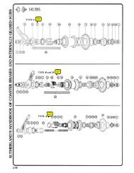
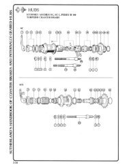
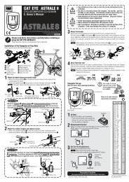
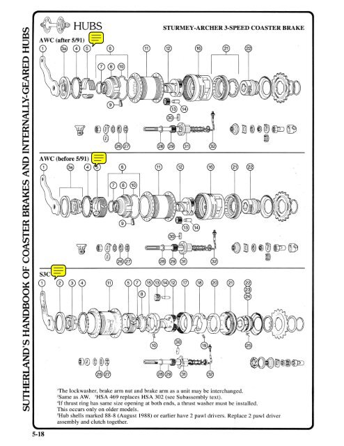
STURMEY·ARCHER 3·SPEED COASTER BRAKE<br />
A WC (after 5/91)<br />
~ ~j)~~<br />
@@<br />
~~@~~<br />
@) @@<br />
<strong>S3C</strong><br />
«<br />
~<br />
@OOlQj@l~<br />
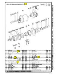
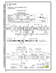
'The lockwasher, brake arm nut and brake arm as a unit may be interchanged.<br />
2Same as AW. 3HSA 469 replaces HSA 302 (see Subassembly text).<br />
4If thrust ring has same size opening at both ends, a thrust washer must be installed.<br />
This occurs only on older models.<br />
5Hub shells marked 88-8 (August 1988) or earlier have 2 pawl drivers. Replace 2 pawl driver<br />
assembly and clutch together.<br />
5·18
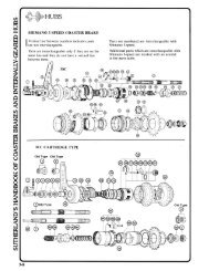
STURMEY-ARCHER <strong>S3C</strong><br />
3-SPEED COASTER BRAKE<br />
DISASSEMBL Y AND ASSEMBLY<br />
o DISASSEMBLY I<br />
Loosen but do not remove<br />
cone locknut and brake arm<br />
nut.<br />
..<br />
Next Step<br />
0DISASSEMBLY I<br />
brake arm<br />
nut<br />
Adjust bearing and lock brake arm nut<br />
in place with locknut.<br />
I ASSEMBLY.<br />
..<br />
Next Step<br />
The right-hand ball ring may<br />
have a double start thread. If<br />
the ball ring is replaced in the<br />
opposite position, the wheel<br />
may need retruing. To<br />
facilitate proper reassembly,<br />
mark the ball ring at the<br />
point nearest the lubricator.<br />
drift punch<br />
Tighten right-hand ball ring with a<br />
hammer and drift punch.<br />
I ASSEMBLY • .<br />
Place a drift punch as shown<br />
and loosen the ball ring by<br />
..<br />
rapping the punch firmly with<br />
a hammer. Do not try to<br />
unscrew it completely.<br />
Next Step<br />
o DISASSEMBLY I<br />
Remove cone locknut, lock<br />
washer, and brake arm nut.<br />
The brake arm, dust cap and<br />
left-hand cone may come off<br />
separately or as a unit. They<br />
can easily be pressed apart<br />
if required. Remove ball<br />
retainer.<br />
..<br />
Next Step<br />
Next Page<br />
cone locknut ,<br />
lock washe~<br />
brake arr~<br />
@<br />
nut~<br />
Install brake arm nut, lock washer<br />
and cone locknut finger tight.<br />
...<br />
Next Step<br />
brake arm~ ~ ..<br />
dmt ca~ Replace ball retainc< flat ,ide up. If<br />
retainer will not seat properly, check<br />
left-hand a thrust plate and pawl ring installation<br />
cone<br />
(step 3). Install cone, dust cover and<br />
ball / " brake arm (brand name facing out).<br />
retainer<br />
The inward face of the cone has three<br />
slots; the two wide slots engage the brake<br />
band tabs, the narrow slot engages the<br />
brake actuating spring. It may be<br />
necessary to rotate the spring before<br />
installing the cone .<br />
I ASSEMBLY.<br />
5-20
STURMEY-ARCHER <strong>S3C</strong><br />
3-SPEED COASTER BRAKE<br />
DISASSEMBL Y AND ASSEMBLY<br />
o DISASSEMBLY I<br />
Unscrew right-hand ball ring<br />
from the bottom of hub shell<br />
and remove cartridge.<br />
..<br />
Next Step<br />
hub<br />
right-hand ball .<br />
*<br />
HUBS<br />
• Next Step<br />
Preceding Page<br />
Without inverting cartridge, slip it<br />
into the l;l.Ub shell and thread ball ring<br />
finger tight. If the mark made during<br />
disassembly is not beside the lubricator,<br />
remove and restart cartridge. Do not<br />
tip or invert hub until left-hand locknut<br />
has been installed in the next step.<br />
I ASSEMBLY.<br />
0DISASSEMBLY I<br />
Remove brake band, thrust<br />
plate and planet cage pawl<br />
ring. If required brake<br />
actuating spring can be<br />
pried off thrust plate with<br />
a thin-bladed screwdriver.<br />
brake<br />
pinion pin end<br />
Next Step.<br />
Turn assembly over. Install brake<br />
actuating spring on thrust plate if it was<br />
removed: Viewed as shown hooked end<br />
of spring must be clockwise from gap.<br />
Incorrect installation will cause excessive<br />
drag and wear.<br />
Rotate pinion pins so the flats face<br />
outwards. Insert tabs of planet cage pawl<br />
ring into slots on thrust plate. Screw the<br />
pawl ring and thrust plate onto the<br />
planet cage until pawl ring seats on the<br />
planet cage. Install brake band, tabs up.<br />
G)DISASSEMBLY I<br />
Hold down ball ring while<br />
removing right-hand locknut,<br />
lock washer, cone clutch<br />
spring, spring cap and driver!<br />
(rotate driver to disengage<br />
driver pawls). If driver<br />
catches on ball ring, remove<br />
both parts together; be careful<br />
not to damage pawl springs<br />
when separating them. Lift<br />
off ball ring, ratchet ring and<br />
gear ring pawl ring.<br />
ratchet rin<br />
beveled edge--!~.~/r:J<br />
gear ring tab<br />
keyway<br />
Next Step.<br />
Install ball ring. Push pawls in and<br />
rotate ring until seated over pawls.<br />
Install driver.! Push pawls in and turn<br />
driver clockwise until it seats in ball ring.<br />
Install spring and spring cap.! Install<br />
cone, lock washer and locknut. Adjust<br />
bearing. If bearing runs rough, check<br />
spring cap.!<br />
Replace gear ring pawl ring beveled<br />
edge down. Pawls must point clockwise<br />
when viewed from above. Top face of<br />
ring should be flush with top of gear<br />
ring tabs.<br />
Install ratchet ring. Ratchet ring keys<br />
must be engaged in keyways of the gear<br />
ring tabs. If the keys are positioned<br />
beside the gear ring tabs, low gear may<br />
not engage properly.<br />
ASSEMBLY<br />
!Old model spring caps are too l ~rge to fitthrough the driver. On these hubs, the spring and cap are removed<br />
after and installed before the driver. Otherwise the spring cap will be compressed between the cone and the<br />
bearing with damage to both. Upon installation the driver must be held in place against the spring until the<br />
cone is installed.<br />
5-21
* HUBS<br />
0DISASSEMBLY I<br />
Remove gear ring, clutch and<br />
axle key. Push out pinion<br />
pins and remove pinions.<br />
Pry off planet cage circlip and<br />
remove planet cage.<br />
ge.,'ingd<br />
clutch<br />
..<br />
Next Step<br />
Preceding Page<br />
STURMEY-ARCHER <strong>S3C</strong><br />
3-SPEED COASTER BRAKE<br />
DISASSEMBLY AND ASSEMBLY (cont.)<br />
Slide planet cage over left end of axle<br />
past circlip groove and replace circlip.<br />
Replace pinions and pinion pins. Orient<br />
the pins as shown. Center axle key in the<br />
bottom of the axle slot with threaded<br />
hole parallel to axle. Slide clutch over<br />
axle key. Clutch should contact face of<br />
planet cage and engage pinion pins.<br />
Install gear ring.<br />
circlip-O<br />
IDISASSEMBLY I<br />
Ball Ring, Driver and<br />
Pawl Rings<br />
Bearings. Remove dust cover<br />
with a thin-bladed screwdriver.<br />
Work slowly around<br />
cover to avoid deforming it.<br />
Lift out balls or ball retainer.<br />
Pawls. Pawl springs can be<br />
removed with the pawls in<br />
place, although some<br />
deformation usually results.<br />
Ease the hooked end of the<br />
spring over the side or long<br />
end of pawl to the other side.<br />
Spread the ends of spring <<br />
SUBASSEMBLIES<br />
dust cap<br />
ball<br />
retainer<br />
balls<br />
Ball Ring, Driver and<br />
Pawl Rings<br />
Bearings. Install balls or ball retainer.<br />
Orient retainer as shown. Start dust<br />
cover straight by hand and tap home<br />
with a soft hammer.<br />
ballring~ Pawls. If only pawl springs have been<br />
driver<br />
removed, springs may be fitted with<br />
pawl Va pawls in place. Use only new style pawl<br />
_____________ springs. Early types tend to break.<br />
Holding spring by hooked end, hook<br />
Driver Pawl Springs straight end around pawl pin beside<br />
current obsolete styles pawl. Ease hooked end over the side<br />
style (breakage prone)<br />
or long end of pawl. Straight end must<br />
come to bear on piece body and hooked<br />
end on inside surface of pawl slightly<br />
behind driving edge.<br />
and slide out.<br />
bright finish dull bright<br />
HSA 469 finish finish If pawls were removed, install pawl,<br />
If pawls are to be removed, ------------- pawl spring and pin together. Make sure<br />
Q<br />
springs are best removed at I pawls are oriented as shown. Straight .<br />
h<br />
. R' d I ' P anet cage gear ring<br />
t at tIme. IVete paw pms pawl ring pawl ring solid pins must be lightly riveted over.<br />
can be removed only by<br />
File end of pin flush. Hollow pins are<br />
drilling. Hollow pawl pins can ~ ~ driven in with a soft hammer. Grooved<br />
be driven out with the correct o~ ~_. /6' ~river pawl pins are installed groove first<br />
size drift punch. Some drivers . and retained by a circlip around the<br />
use removable pawl pins held<br />
driver.<br />
in place by a circlip. Do not I pawl I<br />
mix up pawl sprin'Es.<br />
--=:::::::,__ I ASSEMBLY I<br />
s prlngs ___ ~<br />
HSA 253 HSA 120<br />
5-22
STURMEY-ARCHER <strong>S3C</strong><br />
3-SPEED COASTER BRAKE<br />
DISASSEMBLY AND ASSEMBLY (cont.)<br />
CLEANING<br />
Clean all parts, including outside of hub<br />
shell and axle bore, in a suitable solvent.<br />
Be very careful not to introduce dirt or<br />
grit after cleaning.<br />
POINTS TO CHECK<br />
Part numbers followed by * refer to A W<br />
parts chart, others to <strong>S3C</strong> or <strong>TCW</strong>-<strong>II</strong>I<br />
parts chart.<br />
I. Clutch (26) and gear ring dogs (14)<br />
for rounded or chipped driving edges<br />
(rounqing to a radius of even \164"<br />
(0.4 mm) at the corners can cause hub<br />
to slip out of gear)<br />
2. Pawls (12*, 19,21*), ball ring (18), lefthand<br />
ball cup (5) and ratchet ring (17)<br />
for rounded or chipped driving edges<br />
3. Sun pinion (24), planet pinions (<strong>II</strong>)<br />
and gear ring (14) for worn or chipped<br />
teeth<br />
4. Bearing surfaces of left-hand cone (3),<br />
left-hand ball cup (5), ball ring (18),<br />
driver (19), right-hand cone (5*) and<br />
pinion pins (12) for wear and pitting<br />
5. Axle key (25) and indicator for stripped<br />
threads<br />
6. Clutch spring (32*) and brake actuating<br />
spring (7) for size and tension<br />
7. Dustcaps and ball retainers for<br />
straightness<br />
8. All threaded parts for worn or<br />
damaged threads<br />
9. Axle (24) for straightness<br />
10. Planet cage (13) and thrust plate (8)<br />
threads for wear or roughness<br />
<strong>II</strong>. Thrust plate (8) and brake band (6)<br />
serrations for wear<br />
12. Brake band (6) and hub shell (5) for<br />
wear or glazing<br />
LUBRICATION<br />
Lubricate ball retainers by filling the spaces<br />
between balls with grease. Lubricate hub<br />
shell and brake band liberally with a hightemperature<br />
grease. Be careful not to grease<br />
pawls. Lightly oil other internal parts with<br />
a good cycle oil. (WD-40 is too light for<br />
lasting lubrication, 3-in-1 Oil gums up with<br />
age.) Add about two teaspoons (8 ml) of oil<br />
when assembled.<br />
5-23
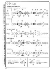
~HUBS<br />
~<br />
STURMEY-ARCHER <strong>AWC</strong><br />
3-SPEED COASTER BRAKE<br />
DISASSEMBLY AND ASSEMBLY<br />
C!:)DISASSEMBLY 1<br />
locknut ~----t.!~<br />
lockwasher -----{<br />
brake arm nut -----+,.~.....l<br />
brake arm ---)<br />
dustcap and cone assembly --~~~~~<br />
Remove left-hand locknut, lockwasher,<br />
brake arm nut and brake<br />
arm. Remove cone and dustcap<br />
assembly and ball retainer. For<br />
hubs manufactured 5/91 and<br />
after, cone and dustcap assembly<br />
are one piece. Tum upside down<br />
so the brake shoes fall out.<br />
..<br />
Next Step<br />
STURMEY-ARCHER <strong>AWC</strong><br />
3-SPEED COASTER BRAKE<br />
DISASSEMBLY AND ASSEMBLY (cont.)<br />
G) DISASSEMBLY I<br />
Remove the gear ring assembly.<br />
Remove the clutch and axle key<br />
from axle. Remove pinion pins<br />
to release planet pinions from the<br />
planet cage. Using snap ring-pliers,<br />
remove planet cage circlip<br />
and remove planet cage.<br />
planet cage ---\<br />
STURMEY-ARCHER <strong>AWC</strong><br />
3-SPEED COASTER BRAKE<br />
DISASSEMBLY AND ASSEMBLY<br />
..<br />
(cont.)<br />
Next Step<br />
Preceding Page<br />
gear ring assembly<br />
(1---- clutch<br />
r-Q- pinion pin<br />
~ planet pinion<br />
axle circlip ---~~<br />
Slide planet cage assembly over<br />
left end of axle (side without<br />
axle key slot) over circlip groove<br />
and install new circlip. Clamp<br />
left end of axle in a vise (axle key<br />
slot up). Replace pinions and<br />
pinion pins. Orient the pins as<br />
shown. Center axle key into bottom<br />
of axle slot with threaded<br />
hole visible when looking down<br />
into slot. Install clutch over end<br />
of axle. Install gear ring assembly<br />
so that planet pinions mesh<br />
with the gear ring.<br />
I ASSEMBLY.<br />
5-26
STURMEY-ARCHER <strong>AWC</strong><br />
3-SPEED COASTER BRAKE<br />
DISASSEMBLY AND ASSEMBLY (cont.)<br />
HUBS~<br />
~<br />
CLEANING<br />
Clean all parts, including outside of hub shell<br />
and axle bore, in a suitable solvent. Be very<br />
careful not to introduce dirt or grit after cleaning.<br />
POINTS TO CHECK<br />
1. All threaded parts for worn or damaged<br />
threads. If hub shell is marked 88-8 or earlier,<br />
both clutch and driver assembly must be<br />
replaced at the same time.<br />
2. Pinions (13), axle (29) and gear ring assembly<br />
(16) for worn gear teeth.<br />
3. Axle (29) for straightness.<br />
4. Gear ring assembly (16) and driver assembly<br />
(22) for wear and chipping. Drag spring on<br />
gear ring assembly assembly should move<br />
freely. Clutch (31) should slide easily into<br />
driver assembly. Manufacturer recommends<br />
replacing either assembly entirely with new<br />
factory-fitted assembly if any part of subassembly<br />
is not suitable.<br />
5. Hub shell (11) for condition of LH ball track,<br />
ratchet and braking surface.<br />
6. Ball cage assembly (4) should have 24 bearings<br />
if assembly is separate from dustcap,<br />
14 bearings if ball cage and dustcap seal are<br />
integral.<br />
7. Pawl (9) and pawl spring (10) in brake actuator<br />
assembly (6). Drag spring (7) should easily<br />
turn clockwise and have great resistance<br />
when rotated counterclockwIse.<br />
8. Brake arm (1). Replace if damaged.<br />
9. Brake band or shoe segments (5) for wearing<br />
and glazing.<br />
LUBRICATION<br />
Lubricate ball retainers by filling the spaces<br />
between balls with grease. Lubricate hub shell<br />
and brake shoes liberally with a high-temperature<br />
grease. Be careful not to grease the pawls.<br />
Lightly oil other internal parts with a good cycle<br />
oil, (WD-40 is too light for lasting lubrication,<br />
3-in-l Oil gums up with age.) Add about two<br />
teaspoons (8 ml) of oil when assembled.<br />
5-27