Official Instructions (PDF) - Sheldon Brown
Official Instructions (PDF) - Sheldon Brown
Official Instructions (PDF) - Sheldon Brown
- No tags were found...

You also want an ePaper? Increase the reach of your titles
YUMPU automatically turns print PDFs into web optimized ePapers that Google loves.
1<br />
9<br />
®<br />
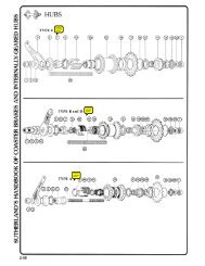
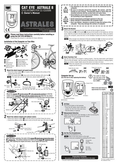
Installation of the Computer on Your Bike<br />
The computer comes with the following parts:<br />
1 Bracket<br />
2 Cord<br />
3 Speed Sensor<br />
(Long Cord)<br />
4 Cadence Sensor<br />
(Short Cord)<br />
1<br />
Rear wheel<br />
spoke<br />
2<br />
2<br />
5<br />
3<br />
4<br />
8<br />
6<br />
7<br />
5 Sensor Rubber Pad<br />
6 Wheel Magnet<br />
7 Cadence Magnet<br />
8 Bracket Rubber Pad<br />
9 Nylon Ties (10)<br />
6<br />
6<br />
9<br />
Mount the magnets 6 and the sensors 3 in the appropriate positions so that the<br />
center of each magnet 6 aligns with the marked sensor line when the rear wheel<br />
and crank arm are rotated. The magnet should be no more than 5mm from the sensor.<br />
Left chainstay<br />
3<br />
7<br />
7<br />
4<br />
CAT EYE ASTRALE 8<br />
CYCLOCOMPUTER CC-CD200N<br />
E: Owner’s Manual<br />
ASTRALE8<br />
U.S. Pat. Nos.4633216/4642606/5226340/5236759 Pat. and Design Pat. Pending<br />
Copyright © 2002/2003 CAT EYE Co. Ltd.<br />
CCMCD2N-030531 066600252 1<br />
Please read these instructions carefully before installing or<br />
using the CAT EYE ASTRALE 8.<br />
Please keep this manual in a safe place for future reference.<br />
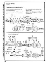
Mount the wheel magnet and speed sensor<br />
•Mount the wheel magnet 6 on a spoke of the rear wheel so the surface of the<br />
magnet faces the sensor.<br />
• Mount the speed sensor 3 (long cord) on the left chainstay with nylon ties 9.<br />
Note The nylon ties can only be used once, please install with care.<br />
Important Note<br />
Marked Line<br />
The smooth edge of the zip<br />
tie should be on the outside<br />
4<br />
3<br />
3<br />
6<br />
2<br />
9<br />
7<br />
1<br />
Left chainstay<br />
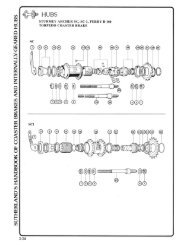
Mount the cadence magnet and cadence sensor.<br />
• Mount the cadence magnet 7 on the left crank arm so that it faces the sensor.<br />
• Secure the cadence sensor 4 (short cord) on the left chain stay with nylon ties 9.<br />
Sensor Side<br />
Sensor Side<br />
Center<br />
3<br />
Kilometer<br />
MODE<br />
9<br />
Inward Side of<br />
The Crank Arm<br />
Left Chain Stay<br />
Marked Line<br />
Center<br />
Rear wheel spoke<br />
Within 5 mm<br />
Important Note<br />
When the crank is spinning, the center of the magnet 7 should pass in front of the sensor<br />
4 marking line. The distance between the sensor and the magnet 7 should be within<br />
5mm. After adjusting the magnet and sensor, secure tightly with nylon ties.<br />
Left Chain Stay<br />
Adjust<br />
Adjust<br />
3<br />
9<br />
Within 5 mm<br />
Crank Arm<br />
3<br />
4<br />
Warning<br />
Important<br />
Note<br />
Mount The Bracket<br />
Secure the cord by fastening it to the frame with zip ties at regular intervals.<br />
Put the rubber pad 8 on the bracket 1 and secure the bracket on the handle bar with the<br />
screw. Slide the computer into the bracket until you hear the click sound. When you need to<br />
remove the computer, press the lever on the handlebar bracket and slide the computer<br />
forward.<br />
Note Allow enough wire clearance in the area marked with to insure you can turn<br />
the handlebars all the way from side to side without pulling the wire.<br />
SET<br />
•Pay attention to the road or trail! Do not be distracted by the<br />
computer.<br />
• Be sure to securely mount the magnet, the sensor, and the<br />
bracket on your bicycle. Periodically check to insure they are<br />
mounted securely and the screws have not come loose.<br />
• Keep batteries out of reach of small children. Dispose of batteries<br />
according to local regulations.<br />
• Avoid unnecessary prolonged exposure to the sun.<br />
• Never attempt to disassemble the computer head.<br />
• Don’t use thinner, benzene or alcohol to wipe the surface of the<br />
computer. They may damage the surface of computer.<br />
SET<br />
1<br />
8<br />
MODE<br />
START/STOP<br />
OK<br />
Computer Set-up<br />
(For first use or after replacing the battery)<br />
SET Button<br />
START/STOP Button<br />
MODE Button<br />
AC Button<br />
All Clear<br />
1 Push the AC button on the backside.<br />
* Push the AC button when using this<br />
system for the first time and every<br />
time the battery is replaced.<br />
Measurement Selection<br />
2 Select the measurement unit, kilometer or mile, by pushing the<br />
MODE button. Fix it by pushing the SET button.<br />
Mile<br />
Set The Tire Circumference<br />
3 Set the tire circumference in mm.<br />
Note Refer to the chart shown on the right.<br />
Setting is fixed and completed by pushing the SET button.<br />
Increase the<br />
number<br />
Max. 2999 mm<br />
!<br />
Contact Point<br />
Decrease<br />
the number<br />
Min. 10 mm<br />
9<br />
You need to know<br />
your tire size or the<br />
roll out length of your<br />
tire in MM's.<br />
Refer to the chart below for<br />
approximate tire lengths.<br />
Slide<br />
1<br />
Basic Functions Test<br />
Spin the rear wheel to see if Speed is reading properly. Push the mode button until Cadence<br />
(Cdc) is in the sub-display. Spin the crank arm backwards to test if Cadence is reading properly.<br />
When you receive a signal, tightly secure the sensor so it does not move.<br />
Note When the computer does not indicate the speed/cadence, check the position of the<br />
magnet and the sensor.<br />
Rotate the rear wheel.<br />
AC Button<br />
Preparation Complete.<br />
(the screen will show the time measurement in this state)<br />
* The auto mode is ON in this state.<br />
Lever<br />
Rotate the crank arm<br />
OK<br />
L mm<br />
Tire size L(mm)<br />
12 x1.75 935<br />
14 x 1.50 1020<br />
14 x 1.75 1055<br />
16 x 1.50 1185<br />
16 x 1.75 1195<br />
18 x 1.50 1340<br />
18 x 1.75 1350<br />
20 x 1.75 1515<br />
20 x 1-3/8 1615<br />
22 x 1-3/8 1770<br />
22 x 1-1/2 1785<br />
24 x 1 1753<br />
24 x 3/4 Tubular 1785<br />
24 x 1-1/8 1795<br />
24 x 1-1/4 1905<br />
24 x 1.75 1890<br />
24 x 2.00 1925<br />
24 x 2.125 1965<br />
26 x 7/8 1920<br />
26 x 1(59) 1913<br />
26 x 1(65) 1952<br />
26 x 1.25 1953<br />
26 x 1-1/8 1970<br />
26 x 1-3/8 2068<br />
26 x 1-1/2 2100<br />
26 x 1.40 2005<br />
26 x 1.50 2010<br />
26 x 1.75 2023<br />
26 x 1.95 2050<br />
26 x 2.00 2055<br />
26 x 2.10 2068<br />
26 x 2.125 2070<br />
26 x 2.35 2083<br />
26 x 3.00 2170<br />
27 x 1 2155<br />
27 x 1-1/8 2161<br />
27 x 1-1/4 2161<br />
27 x 1-3/8 2169<br />
650 x 35A 2090<br />
650 x 38A 2125<br />
650 x 38B 2105<br />
700 x 18C 2070<br />
700 x 19C 2080<br />
700 x 20C 2086<br />
700 x 23C 2096<br />
700 x 25C 2105<br />
700 x 28C 2136<br />
700 x 30C 2170<br />
700 x 32C 2155<br />
700C Tubular 2130<br />
700 x 35C 2168<br />
700 x 38C 2180<br />
700 x 40C 2200<br />
Tire size is usually shown on<br />
the sidewall of tires.
Computer Operations<br />
Selection of the data-display mode (bottom of the screen)<br />
Press the Mode button to navigate to each of the sub-displays listed on the right.<br />
Press and hold the mode button for two seconds in any mode to display the Clock Time.<br />
Start or Stop of Measurements<br />
Measurement<br />
The computer can be programmed to run in either MANUAL<br />
Unit Icon<br />
MODE or AUTO TIME MODE. In Manual Mode you must press<br />
the START / STOP button to turn on and off the Timer, which<br />
records Distance and Average Speeds. In Auto Time the computer<br />
turns the Timer on and off depending on a signal from the<br />
sensor.<br />
When you push the button, Elapsed Time, Average Speed and<br />
Trip Distance are recorded, and stopped with the second push<br />
of the button.<br />
• Auto Time Mode (Automatic Measurement)<br />
When the icon is lit, the measurements are automatically<br />
done. This is called auto-mode in which the rotation of the wheel<br />
is detected to make the measurements start or stop automatically.<br />
(When the icon is lit, you cannot start or stop the measurements<br />
by pushing the START/STOP button)<br />
• Manual Measurements<br />
When you don’t see the icon on the screen, you can start or<br />
stop the measurements by pushing the START/STOP button.<br />
When you push the button, Elapsed Time, Average Speed and<br />
Trip Distance are started, and stopped with the second push of<br />
the button.<br />
START/STOP<br />
• How to set ON or OFF the Auto-Mode<br />
Push the SET button while Elapsed Time (Tm) Trip Distance SET Tm<br />
(Dst) or Average Speed (Av) is displayed, then the icon is<br />
Dst<br />
“lit” (ON) or turned OFF.<br />
Av<br />
Resetting Elapsed Time, Trip Distance, Average and Max.<br />
Speed<br />
Push the MODE button and the START/STOP button at the same<br />
time while the measurements other than Odometer, Elapsed<br />
time, Maximum Speed, Average Speed and Trip Distance are<br />
zeroed. The Odometer cannot be reset.<br />
While Elapsed Time,<br />
Trip Distance or Average<br />
Speed is displayed<br />
MODE<br />
Computer Functions<br />
START/STOP<br />
• Power-Saving Function<br />
When no signal has been received for about 1 hr, the computer switches to powersaving<br />
mode and only displays the Clock. When any button is pushed or the bicycle<br />
is riden, the measurement mode comes back.<br />
• Selection of The Data-display Mode<br />
In Auto-Mode you can choose between Speed or Cadence to be displayed in the top<br />
screen.<br />
Speed is initially selected in the upper display.<br />
When the computer is in mode,<br />
press the START/STOP button. Cadence<br />
will now appear in the upper display. Speed<br />
AT<br />
will be in the lower display. Switch it back<br />
with the same procedure.<br />
Speed<br />
START/STOP<br />
Cadence<br />
Display for Measurements<br />
Speed<br />
0.0 (4.0) - 300.0 km/h<br />
[0.0 (3.0) - 185 mph]<br />
or<br />
Cadence<br />
0.0 (20.0) - 299.9 rpm<br />
Mode Selection Illustrations (bottom of the screen)<br />
Cdc Cadence 0(20) - 299 rpm<br />
or<br />
Speed<br />
0.0 (4.0) - 300.0 km/h<br />
MODE<br />
For 2 sec.<br />
Troubleshooting<br />
No display appears.<br />
Is the battery dead<br />
Replace it and do all clear procedure.<br />
Strange data appears<br />
Do all clear procedure.<br />
Data of odometer is also erased.<br />
Measurements do not start when the START/STOP button is pushed.<br />
Is the icon ON<br />
Turn the Auto-Mode off to enable the start or stop of the measurements by manual operation<br />
of the button.<br />
No speed or cadence data can be measured.<br />
(If the speed or cadence data is not displayed, have the contact<br />
points short-circuited a few times by a metal plate. In the case<br />
that this short-circuiting is detected by the computer, the computer<br />
is considered normal and the bracket and the sensor possibly<br />
have the cause of trouble.)<br />
Is the gap between the sensor and the magnet too big<br />
(should be within 5 mm)<br />
Does the marked line of the sensor align with the center of<br />
the magnet<br />
Adjust the position of the magnet and the sensor.<br />
Wipe the contact points of the bracket or computer clean.<br />
MODE<br />
The contacts to be short-circuited<br />
intermittently are located<br />
on the back.<br />
Speed<br />
Is the cord broken Even if the outside of the cord looks normal, there could be damage.<br />
Replace the bracket and sensor set with a new one.<br />
Additional troubleshooting at www.cateye.com<br />
Cadence<br />
While any measurement is<br />
displayed on the screen<br />
Odo<br />
Odometer<br />
0.0 - 99999 km [mile]<br />
Mx<br />
Maximum speed<br />
0.0 (4.0) - 300.0 km/h<br />
[0.0 (3.0) - 180.5 mph]<br />
Av<br />
Average Speed<br />
0.0 - 300 km/h [0.0 - 185.0 mph]<br />
Dst<br />
Trip Distance<br />
0.00 - 999.99 km[mile]<br />
Tm<br />
Elapsed Time<br />
0:00’00” - 9:59’59”<br />
Return to Elapsed<br />
Time display<br />
Clock<br />
0:00 - 23:59<br />
[1:00 - 12:59]<br />
Auto-mode Icon<br />
When lit, the measurements<br />
starts or stops<br />
automatically.<br />
If Elapsed Time exceeds 27 hours or Trip<br />
Distance exceeds 999.99km, Average<br />
Speed shows E. and ceases calculation.<br />
MODE<br />
Power-Saving Screen<br />
(When no signal is received for about 1 hr. the<br />
screen switches to the power-saving mode)<br />
SET<br />
Return to Clock display<br />
SET<br />
When the measurements<br />
are stopped.<br />
MODE<br />
START/STOP<br />
When you push either of the MODE<br />
button or the START/STOP button<br />
or you ride the bicycle, the display<br />
comes back to the measurement<br />
display.<br />
You can program the tire size.<br />
Range of set: 10 - 2999 mm<br />
When the measurements<br />
are stopped<br />
SET<br />
Increase<br />
the number<br />
Decrease<br />
the number<br />
SET<br />
Return to the Elapsed Time<br />
Setting The Clock Time<br />
24 hour or 12 hour system is to be used with km/h or mph<br />
unit respectively.<br />
Set the hour<br />
MODE<br />
Increase the number<br />
START/STOP<br />
Set the minute<br />
Specifications<br />
Battery/Its Life : ----------------------------- A Lithium Battery (CR2032), Approx:3 yrs.<br />
(Approx:1 hr per day usage.)<br />
Control System : ---------------------------- 4-bit 1-chip micro-computer (with a crystal oscillator)<br />
Display : -------------------------------------- Liquid crystal display<br />
Sensing System : --------------------------- No-contact magnetic sensor<br />
Range of tire circumference setting : ----- 10 mm - 2999 mm (Initial value 2096 mm)<br />
Range of Operational Temperature : ------ 0°C - 40°C (32°F - 104°F)<br />
Dimension and Weight(Computer) : ------ 38 x 54 x 17.5 mm [1-1/2 x 2-1/8 x 11/16"] / 28 g [1.0 oz]<br />
* The factory-loaded battery life might be shorter than the above-mentioned specification.<br />
* The specifications and design are subject to change without notice.<br />
Limited Warranty<br />
2-Year Warranty : Computer Head Only<br />
(Bracket sensor and batteries are not covered under the warranty)<br />
If any trouble or damage occurs during normal use, the product computer will be repaired or replaced<br />
free of charge. Type your name, address, telephone number or e-mail address, date of purchase and<br />
the situation of trouble and send it back together with the product to the closest address below. Transportation<br />
charges shall be borne by the customer. After being repaired, the product will be shipped<br />
back to the customer.<br />
CO.,LTD. 2-8-25, Kuwazu, Higashi Sumiyoshi-ku, Osaka 546-0041 Japan<br />
Attn.: CAT EYE Customer Service Section<br />
Service & Research Address for North American Consumers:<br />
CAT EYE Service & Research Center<br />
1705 14th St. 115 Boulder, CO 80302<br />
Phone: 303-443-4595 Toll Free: 800-5CATEYE<br />
Fax: 303-473-0006 e-mail: service@cateye.com<br />
* Accessory parts are available for the customers as shown below. URL: http://www.cateye.com<br />
Standard Parts<br />
#169-9400N<br />
Bracket Sensor Kit (Rear wheel sensor)<br />
#169-9757N<br />
Attachment Kit<br />
#169-9765<br />
Cadence Magnet<br />
#169-9691N<br />
Wheel Magnet<br />
#166-5150<br />
Lithium Battery (CR2032)<br />
Maintenance<br />
• To clean the computer or the attached parts, use diluted neutral<br />
detergent on a soft cloth and wipe it off with a dry cloth.<br />
Replacing The Battery<br />
When the display becomes dim, replace the battery.<br />
• Put a lithium battery CR2032 in the computer with the (+) mark<br />
facing up.<br />
• After replacing the battery, refer to "Computer Set-Up" and do an<br />
all clear operation.<br />
Close<br />
Open<br />
Optional Parts<br />
#169-9402N<br />
Center Mount Bracket Kit (Rear wheel sensor)<br />
#169-9404N<br />
Stem Mount<br />
Bracket Kit<br />
(Rear wheel sensor)<br />
#169-9403N<br />
Bracket Sensor Kit for Aero Bar<br />
(Rear wheel sensor)<br />
#169-9760<br />
Magnet for Composit Wheel