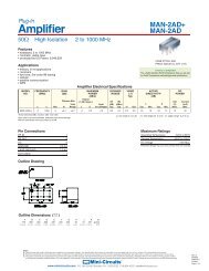
PSA4-5043+ - Mini-Circuits
PSA4-5043+ - Mini-Circuits
PSA4-5043+ - Mini-Circuits

You also want an ePaper? Increase the reach of your titles
YUMPU automatically turns print PDFs into web optimized ePapers that Google loves.
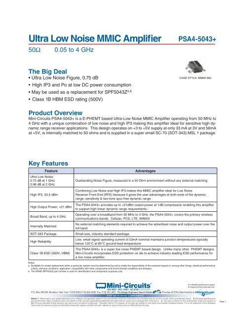
Ultra Low Noise MMIC Amplifier <strong>PSA4</strong>-<strong>5043+</strong><br />
50Ω 0.05 to 4 GHz<br />
The Big Deal<br />
• Ultra Low Noise Figure, 0.75 dB<br />
• High IP3 and Po at low DC power consumption<br />
• May be used as a replacement for SPF5043Za,b • Class 1B HBM ESD rating (500V)<br />
Product Overview<br />
<strong>Mini</strong>-<strong>Circuits</strong> <strong>PSA4</strong>-<strong>5043+</strong> is a E-PHEMT based Ultra-Low Noise MMIC Amplifier operating from 50 MHz to<br />
4 GHz with a unique combination of low noise and high IP3 making this amplifier ideal for sensitive high dynamic<br />
range receiver applications. This design operates on +3 to +5V supply at only 33 mA at 3V and 56mA<br />
at +5V, is internally matched to 50 ohms and is supplied in a super small SC-70 (SOT-343) MSL 1 package.<br />
Key Features<br />
CASE STYLE: MMM1362<br />
Feature Advantages<br />
Ultra Low Noise:<br />
0.75 dB at 1 GHz<br />
Outstanding Noise Figure, measured in a 50 Ohm environment without any external matching<br />
0.98 dB at 2 GHz<br />
High IP3, 33.5 dBm<br />
Combining Low Noise and High IP3 makes this MMIC amplifier ideal for Low Noise<br />
Receiver Front End (RFE) because it gives the user advantages at both ends of the dynamic<br />
range: sensitivity & two-tone spur-free dynamic range<br />
High Output Power, +21 dBm<br />
The <strong>PSA4</strong>-<strong>5043+</strong> provides up to +21dBm output power at 1dB compression enabling this amplifier<br />
to support high linear dynamic range requirements.-<br />
Broad Band, up to 4 GHz<br />
Operating over a broadband from 50 MHz to 4 GHz, the <strong>PSA4</strong>-<strong>5043+</strong> covers the primary wireless<br />
communications bands: Cellular, PCS, LTE, WiMAX<br />
Internally Matched<br />
No external matching elements required to achieve the advertised noise and output power over the<br />
full band<br />
SOT-343 Package Small size, industry standard package<br />
High Reliability<br />
Low, small signal operating current of 53mA nominal maintains junction temperatures typically<br />
below 125°C at 85°C ground lead temperature<br />
The <strong>PSA4</strong>-<strong>5043+</strong> is a super low noise PHEMT based design. Unlike many other PHEMT designs.<br />
Class 1B ESD (500V, HBM) <strong>Mini</strong>-<strong>Circuits</strong> incorporates ESD protection on die to achieve industry leading ESD performance for<br />
a low noise amplifier.<br />
Notes:<br />
a. Suitability for model replacement within a particular system must be determined by and is solely the responsibility of the customer based on, among other things, electrical performance<br />
criteria, stimulus conditions, application, compatibility with other components and environmental conditions and stresses.<br />
b. The RFMD SPF5043Z part number is used for identification and comparison purposes only.<br />
<strong>Mini</strong>-<strong>Circuits</strong> ISO 9001 ISO 14001 AS 9100 CERTIFIED<br />
®<br />
P.O. Box 350166, Brooklyn, New York 11235-0003 (718) 934-4500 Fax (718) 332-4661 The Design Engineers Search Engine Provides ACTUAL Data Instantly at minicircuits.com<br />
IF/RF MICROWAVE COMPONENTS<br />
Notes: 1. Performance and quality attributes and conditions not expressly stated in this specification sheet are intended to be excluded and do not form a part of this specification sheet. 2. Electrical specifications<br />
and performance data contained herein are based on <strong>Mini</strong>-Circuit’s applicable established test performance criteria and measurement instructions. 3. The parts covered by this specification sheet are subject to<br />
<strong>Mini</strong>-<strong>Circuits</strong> standard limited warranty and terms and conditions (collectively, “Standard Terms”); Purchasers of this part are entitled to the rights and benefits contained therein. For a full statement of the Standard<br />
Terms and the exclusive rights and remedies thereunder, please visit <strong>Mini</strong>-<strong>Circuits</strong>’ website at www.minicircuits.com/MCLStore/terms.jsp.<br />
®<br />
For detailed performance specs<br />
& shopping online see web site<br />
Page 1
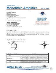
Low Noise, High IP3<br />
Monolithic Amplifier<br />
Product Features<br />
• Ultra Low Noise Figure, 0.75 dB typ. at 1 GHz<br />
• Class 1B ESD rating (500V)<br />
• High IP3, up to 33.5 dBm typ. at 1 GHz<br />
• Output Power at 1dB comp., up to +21 dBm typ.<br />
• Gain, 18.4 dB typ. at 1GHz<br />
• Supply Voltage, +3V, Id=33mA, +5V, Id=56mA<br />
• Aqueous washable<br />
• May be used as a replacement for SPF5043Z a,b<br />
Typical Applications<br />
• Cellular<br />
• ISM<br />
• GSM<br />
• WCDMA<br />
• LTE<br />
• WiMax<br />
• WLAN<br />
• GPS<br />
<strong>Mini</strong>-<strong>Circuits</strong> ®<br />
0.05-4 GHz<br />
<strong>PSA4</strong>-<strong>5043+</strong><br />
CASE STYLE: MMM1362<br />
PRICE: $2.58 ea. QTY. (20)<br />
Function Pin<br />
Number<br />
Description (See Application Circuit, Fig. 2)<br />
RF IN 3 RF input pin (connect to RF-IN via DC blocking cap)<br />
RF-OUT & DC-IN 1<br />
+ RoHS compliant in accordance<br />
with EU Directive (2002/95/EC)<br />
The +Suffix has been added in order to identify RoHS<br />
Compliance. See our web site for RoHS Compliance<br />
methodologies and qualifications.<br />
General Description<br />
<strong>PSA4</strong>-<strong>5043+</strong> is an advanced wide band, high dynamic range, low noise, high IP3, high output power,<br />
monolithic amplifier. Manufactured using E-PHEMT* technology enables it to work with a single positive<br />
supply voltage.<br />
simplified schematic and pin description<br />
RF-IN RF-OUT<br />
and DC-IN<br />
RF OUT<br />
and DC-IN<br />
RF output pin (connected to RF-out via blocking cap C2 and supply voltage Vd<br />
via RF Choke L1)<br />
Connections to ground: use via holes as shown in “Suggested Layout for PCB<br />
GND 2,4<br />
Design” to reduce ground path inductance for best performance.<br />
* Enhancement mode pseudomorphic High Electron Mobility Transistor.<br />
Notes:<br />
a. Suitability for model replacement within a particular system must be determined by and is solely the responsibility of the customer based on, among other things, electrical performance<br />
criteria, stimulus conditions, application, compatibility with other components and environmental conditions and stresses.<br />
b. The The RFMD SPF-5043Z part number is used for identification and comparison purposes only.<br />
For detailed performance specs<br />
& shopping online see web site<br />
ISO 9001 ISO 14001 AS 9100 CERTIFIED<br />
®<br />
P.O. Box 350166, Brooklyn, New York 11235-0003 (718) 934-4500 Fax (718) 332-4661 The Design Engineers Search Engine Provides ACTUAL Data Instantly at minicircuits.com<br />
IF/RF MICROWAVE COMPONENTS<br />
Notes: 1. Performance and quality attributes and conditions not expressly stated in this specification sheet are intended to be excluded and do not form a part of this specification sheet. 2. Electrical specifications<br />
and performance data contained herein are based on <strong>Mini</strong>-Circuit’s applicable established test performance criteria and measurement instructions. 3. The parts covered by this specification sheet are subject to<br />
<strong>Mini</strong>-<strong>Circuits</strong> standard limited warranty and terms and conditions (collectively, “Standard Terms”); Purchasers of this part are entitled to the rights and benefits contained therein. For a full statement of the Standard<br />
Terms and the exclusive rights and remedies thereunder, please visit <strong>Mini</strong>-<strong>Circuits</strong>’ website at www.minicircuits.com/MCLStore/terms.jsp.<br />
GND<br />
GND<br />
RF IN<br />
REV. A<br />
M136218<br />
<strong>PSA4</strong>-<strong>5043+</strong><br />
RS/TH<br />
120629<br />
Page 2
Monolithic MMIC Amplifier<br />
Electrical Specifications (1) at 25°C, Zo=50Ω, (refer to characterization circuit, Fig. 1)<br />
Parameter Condition<br />
(GHz)<br />
Absolute Maximum Ratings (4)<br />
Parameter Ratings<br />
Operating Temperature (5) -40°C to 85°C<br />
Storage Temperature -65°C to 150°C<br />
Channel Temperature 150°C<br />
DC Voltage 6V<br />
Device Current 76 mA<br />
Power Dissipation 380 mW<br />
Input Power (CW) 23 dBm (5 minutes max), 17dBm (continous)<br />
Vd=5.0V (1) Vd=3.0V (1)<br />
<strong>PSA4</strong>-<strong>5043+</strong><br />
Min. Typ. Max. Min. Typ. Max. Units<br />
Frequency Range 0.05 4.0 0.05 4.0 GHz<br />
at DC Volts (Vd) 5.0 3.0 V<br />
DC Current (Id) 58 66 33 mA<br />
0.05 0.73 0.66<br />
0.5 0.65 0.66<br />
Noise Figure<br />
1.0<br />
2.0<br />
0.75<br />
0.98<br />
1.1 0.73<br />
0.94<br />
dB<br />
3.0 1.1 1.1<br />
4.0 1.44 1.3<br />
0.05 25.4 24.3<br />
0.5 22.1 21.2<br />
Gain<br />
1.0<br />
2.0<br />
16.5 18.4<br />
13.3<br />
20.2 17.5<br />
12.5<br />
dB<br />
3.0 10.2 9.6<br />
4.0 8.0 7.2<br />
Input Return Loss<br />
0.05<br />
0.5<br />
7.8<br />
10.5<br />
6.5<br />
9.4<br />
dB<br />
1.0 11.4 10.6<br />
2.0 12.2 11.1<br />
3.0 12.8 10.4<br />
4.0 11.1 9.2<br />
Output Return Loss<br />
0.05<br />
0.5<br />
13.7<br />
15.0<br />
13.2<br />
15.9<br />
dB<br />
1.0 13.9 15.1<br />
2.0 12.5 14.5<br />
3.0 11.7 13.3<br />
4.0 12.8 15.7<br />
0.05 31.0 28.0<br />
0.5 32.1 28.0<br />
Output IP3<br />
1.0<br />
2.0<br />
33.5<br />
32.7<br />
28.7<br />
30.0<br />
dBm<br />
3.0 33.6 31.0<br />
4.0 32.6 31.0<br />
Output Power @1dB compression (2)<br />
0.05 18.9 15.8<br />
0.5 19.3 16.5<br />
1.0<br />
2.0<br />
19.8<br />
20.7<br />
17.4<br />
19.0<br />
dBm<br />
3.0 21.2 19.4<br />
4.0 21.5 19.8<br />
DC Current Variation Vs. Temperature (3) -0.007 -0.007 mA/°C<br />
DC Current Variation Vs. Voltage 0.01 0.01 mA/mV<br />
Thermal Resistance (5) 117 117 °C/W<br />
<strong>PSA4</strong>-<strong>5043+</strong><br />
DC Current Vd=5V<br />
<strong>Mini</strong>-<strong>Circuits</strong> ISO 9001 ISO 14001 AS 9100 CERTIFIED<br />
®<br />
(1) Measured on <strong>Mini</strong>-<strong>Circuits</strong> Characterization test board TB-471+.<br />
See Characterization Test Circuit (Fig. 1)<br />
(2) Current increases at P1dB<br />
(3) (Current at 85°C - Current at -45°C)/130<br />
Current (mA)<br />
(4) Permanent damage may occur if any of these limits are exceeded.<br />
These maximum ratings are not intended for continuous normal operation.<br />
(5) Defined with reference to ground pad temperature.<br />
For detailed performance specs<br />
& shopping online see web site<br />
®<br />
P.O. Box 350166, Brooklyn, New York 11235-0003 (718) 934-4500 Fax (718) 332-4661 The Design Engineers Search Engine Provides ACTUAL Data Instantly at minicircuits.com<br />
IF/RF MICROWAVE COMPONENTS<br />
Notes: 1. Performance and quality attributes and conditions not expressly stated in this specification sheet are intended to be excluded and do not form a part of this specification sheet. 2. Electrical specifications<br />
and performance data contained herein are based on <strong>Mini</strong>-Circuit’s applicable established test performance criteria and measurement instructions. 3. The parts covered by this specification sheet are subject to Page 3<br />
<strong>Mini</strong>-<strong>Circuits</strong> standard limited warranty and terms and conditions (collectively, “Standard Terms”); Purchasers of this part are entitled to the rights and benefits contained therein. For a full statement of the Standard<br />
Terms and the exclusive rights and remedies thereunder, please visit <strong>Mini</strong>-<strong>Circuits</strong>’ website at www.minicircuits.com/MCLStore/terms.jsp.<br />
47-49<br />
49-51<br />
51-53<br />
53-55<br />
55-57<br />
57-59<br />
59-61<br />
61-63<br />
63-65<br />
USL<br />
65-67<br />
>67
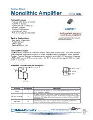
Monolithic MMIC Amplifier<br />
Characterization Test Circuit<br />
1 3/5V<br />
RF-IN<br />
3<br />
2,4<br />
Vd<br />
RF-OUT<br />
BLK-18+<br />
DUT<br />
Bias-Tee<br />
ZX85-12G-S+<br />
TB-471+<br />
<strong>Mini</strong>-<strong>Circuits</strong> ISO 9001 ISO 14001 AS 9100 CERTIFIED<br />
®<br />
P.O. Box 350166, Brooklyn, New York 11235-0003 (718) 934-4500 Fax (718) 332-4661 The Design Engineers Search Engine Provides ACTUAL Data Instantly at minicircuits.com<br />
IF/RF MICROWAVE COMPONENTS<br />
Notes: 1. Performance and quality attributes and conditions not expressly stated in this specification sheet are intended to be excluded and do not form a part of this specification sheet. 2. Electrical specifications<br />
and performance data contained herein are based on <strong>Mini</strong>-Circuit’s applicable established test performance criteria and measurement instructions. 3. The parts covered by this specification sheet are subject to<br />
<strong>Mini</strong>-<strong>Circuits</strong> standard limited warranty and terms and conditions (collectively, “Standard Terms”); Purchasers of this part are entitled to the rights and benefits contained therein. For a full statement of the Standard<br />
Terms and the exclusive rights and remedies thereunder, please visit <strong>Mini</strong>-<strong>Circuits</strong>’ website at www.minicircuits.com/MCLStore/terms.jsp.<br />
®<br />
<strong>PSA4</strong>-<strong>5043+</strong><br />
Fig 1. Block Diagram of Test Circuit used for characterization. (DUT soldered on <strong>Mini</strong>-<strong>Circuits</strong> Characterization Test Board TB-471+)<br />
Gain, Return loss, Output power at 1dB compression (P1 dB), Output IP3 (OIP3) and Noise Figure measured using Agilent’s<br />
N5242A PNA-X microwave network analyzer.<br />
Conditions:<br />
1. Gain: Pin= -25dBm<br />
2. Output IP3 (OIP3): Two tones, spaced 1 MHz apart, 5 dBm/tone at output.<br />
Recommended Application Circuit<br />
(refer to evaluation board for PCB Layout and component values)<br />
Id 3 or 5V (Vs)<br />
L1<br />
C1<br />
C2<br />
RF-IN<br />
3 1<br />
RF-OUT<br />
2,4<br />
Fig 2. Recommended Application Circuit<br />
Note: Resistance of L1, 0.1-0.2Ω typically<br />
I ds<br />
C3<br />
I d<br />
Vs (Supply voltage)<br />
I ds<br />
Product Marking<br />
For detailed performance specs<br />
& shopping online see web site<br />
black body<br />
laser or white ink marking<br />
Page 4
Monolithic MMIC Amplifier<br />
Additional Detailed Technical Information<br />
additional information is available on our dash board. To access this information click here<br />
Performance Data<br />
Case Style<br />
ESD Rating<br />
Start<br />
Visual<br />
Inspection<br />
Reflow 3 cycles,<br />
260°C<br />
Visual<br />
Inspection<br />
MSL Test Flow Chart<br />
Electrical Test SAM Analysis<br />
Soak<br />
85°C/85RH<br />
168 hours<br />
Data Table<br />
Swept Graphs<br />
S-Parameter (S2P Files) Data Set (.zip file)<br />
MMM1362<br />
Plastic molded SOT-343 package, lea finishi: matte tin<br />
Tape & Reel F90<br />
Standard quantities available on reel 7” reels with 20, 50, 100, 200, 500 or 1K devices.<br />
Suggested Layout for PCB Design PL-361<br />
Evaluation Board TB-653+<br />
Environmental Ratings ENV08T2<br />
Human Body Model (HBM): Class 1B (500 to