Installation and Maintenance
Installation and Maintenance
Installation and Maintenance

You also want an ePaper? Increase the reach of your titles
YUMPU automatically turns print PDFs into web optimized ePapers that Google loves.
Renold Roller Chain Catalogue I 81<br />
Chain <strong>Installation</strong> <strong>and</strong> <strong>Maintenance</strong><br />
Important Note<br />
Sprockets should always be designed to be as<br />
close to the supporting bearings as possible.<br />
<strong>Installation</strong> of Chain<br />
Renold Chain should not be assembled on the<br />
sprockets until attention has been paid to:<br />
1. Cleanliness of the sprocket teeth,<br />
particularly if debris of an abrasive nature<br />
(cement dust, weld spatter, etc.), has been<br />
prevalent whilst work was in progress.<br />
2. Temporary positioning of the lower section<br />
of a chaincase if present. In restricted<br />
spaces, manoeuvring of large sections<br />
is often simplified by using the spaces<br />
between shafts which will later be occupied<br />
by the chain.<br />
Ensure the chain is clean <strong>and</strong> free from debris<br />
<strong>and</strong> place around the sprockets, observing<br />
instructions where matched str<strong>and</strong>s are<br />
involved. In chain of two or more str<strong>and</strong>s,<br />
joining is most easily accomplished at the<br />
mid span of the drive, drawing the chain ends<br />
together with a chain clamp or rope tackle<br />
block. Ensure that the strength of the drawing<br />
tackle is sufficient to hold the chain. Chain<br />
weights are shown in the Renold catalogue.<br />
When inserting the joining link of multiplex<br />
chain, ensure the intermediate plates are<br />
assembled. Do not detach the drawing tackle<br />
until the link is completely assembled. When<br />
only partially inserted through inner links, the<br />
weight of the chain on release can “splay”<br />
unsupported bearing pins.<br />
Adjust the chain using the datum mark<br />
mentioned in the preparation section to<br />
retain shaft parallelism.<br />
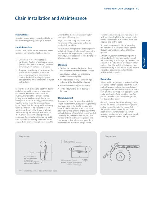
For a chain of average centre distance (30-50<br />
x chain pitch) correct adjustment is when the<br />
mid point of the longest span can be fully<br />
moved by h<strong>and</strong> in accordance with dimension<br />
‘A’ shown in diagram one.<br />
Chaincases<br />
• Position the chaincase bottom sections<br />
with the shafts concentric in their cavities<br />
• Manufacture suitable mountings <strong>and</strong><br />
brackets to ensure rigidity<br />
• Assemble the oil supply <strong>and</strong> return pipe<br />
system <strong>and</strong> the drive to the oil pump<br />
• Assemble top section(s) of chaincase<br />
• Fill the oil sump <strong>and</strong> check delivery to<br />
the chain<br />
Chain Adjustment<br />
To maximise chain life, some form of chain<br />
length adjustment must be provided, preferably<br />
by moving one of the shafts. See diagram<br />
three. If shaft movement is not possible, an<br />
adjustable jockey sprocket engaging with the<br />
unloaded str<strong>and</strong> of the chain is recommended.<br />
Generally, the jockey should have the same<br />
number of teeth as the driver sprocket <strong>and</strong><br />
care should be taken to ensure speed does<br />
not exceed the maximum ratings shown.<br />
The chain should be adjusted regularly so that<br />
with one str<strong>and</strong> tight the slack str<strong>and</strong> can be<br />
moved a distance of 'A' at the mid point. See<br />
diagram one, on this page.<br />
To cater for any eccentricities of mounting,<br />
the adjustment of the chain should be tried<br />
through a complete revolution of the large<br />
sprocket.<br />
Adjustment, as shown in these diagrams, is<br />
achieved either by the movement of one of<br />
the shafts or by use of the jockey sprocket. The<br />
amount of the adjustment provided by either<br />
method should be sufficient to take up chain<br />
wear amounting to two pitches or two percent<br />
elongation above nominal chain length,<br />
whichever is the smaller.<br />
Diagram two<br />
When used for adjustment, a jockey should be<br />
positioned on the unloaded side of the chain,<br />
preferably nearer to the driven sprocket <strong>and</strong><br />
gearing with the outside of the chain; it should<br />
have an initial chain lap of at least three teeth<br />
<strong>and</strong> a free length of chain not less than four<br />
pitches between it <strong>and</strong> the nearest sprocket.<br />
See diagram two above.<br />
Generally, the number of teeth in any jockey<br />
should not be less than the smallest sprocket<br />
<strong>and</strong> care should be taken to ensure that<br />
the speed does not exceed the maximum<br />
recommended. Where necessary, several<br />
sprockets can be used on a single drive, thereby<br />
meeting all possible needs for adjustment.<br />
Section 2<br />
Diagram one<br />
Diagram two<br />
Over-tensioning should be avoided in all cases.